2005 SUZUKI JIMNY leak
[x] Cancel search: leakPage 75 of 687

Downloaded from www.Manualslib.com manuals search engine 1B-14 AIR CONDITIONING (OPTIONAL)
0.05 – 0.15
(0.5 – 1.5)
(4.2 – 21.3)
0.69 – 0.98
(7 – 10)
(100 – 142)Both low and high pres-
sure sides indicate low
readings.
Continuous air bub-
bles are visible through
sight glass.
Output air is slightly
cold.Insufficient refrigerant in
system.
(Refrigerant leaking)Using leak detector,
check for leaks and repair
as necessary.
Recharge refrigerant to a
specified amount.
If the pressure reading is
almost 0 when the mani-
fold gauges are attached,
check for any leaks,
repair them, and evacu-
ate the system.
0.4 – 0.6
(4 – 6)
(56.9 – 85.3)Pressure on low pres-
sure side is high.
Pressure on high pres-
sure side is low.
Both pressure becom-
ing equal right after A/C
is turned OFF.Internal leak in compres-
sor.Inspect compressor and
repair or replace as nec-
essary.
0.35 – 0.45
(3.5 – 4.5)
(50 – 64)
1.96 – 2.45
(20 – 25)
(285 – 355)Pressure on both low
and high pressure
sides is high.
Air bubbles are not visi-
ble even when engine
rpm is lowered.Overcharged A/C sys-
tem.Adjust refrigerant to
specified amount.
Faulty condenser cooling
operation.Clean condenser.
Faulty condenser cooling
fan operation.Inspect and repair con-
denser cooling fan.
Pressure on both low
and high pressure
sides is high.
Low pressure side tub-
ing is not cold when
touched.
Air bubbles are visible
through sight glass.Presence of air in A/C
system.
(Improperly evacuated)Replace receiver / dryer.
Inspect quantity of com-
pressor oil and presence
of contaminants in oil.
Evacuate system and
recharge with fresh
refrigerant.
0.45 – 0.55
(4.5 – 5.5)
(64 – 78)Pressure on both low
and high pressure
sides is high.
Large amount of frost
or dew on the low pres-
sure side tubing.Faulty expansion valve.
Refrigerant flow is not
regulated properly.Replace expansion valve. Condition
Possible Cause Correction MANIFOLD
GAUGEMPa
(kg/cm
2)
(psi)Detail
Lo Hi
Page 82 of 687

Downloaded from www.Manualslib.com manuals search engine AIR CONDITIONING (OPTIONAL) 1B-21
Refrigerant Recovery, Evacuating and Charging
Operation Procedure for Refrigerant Charging
WARNING:
Your eyes should not be exposed to refrigerant (liquid).
Any liquid HFC-134a (R-134a) escaping by accident shows a temperature as low as approximately
–6 °C (21 °F) below freezing point. Should liquid HFC-134a (R-134a) get into your eyes, it may cause
a serious injury. To protect your eyes against such accident, it is necessary to always wear gog-
gles. Should it occur that HFC-134a (R-134a) strikes your eyes(s), consult a doctor immediately.
– Do not use your hand to rub the affected eye(s). Instead, use quantities of fresh cold water to
splash it over the affected area to gradually raise temperature of such area above freezing point.
– Obtain proper treatment as soon as possible from a doctor or eye specialist.
Should the HFC-134a (R-134a) liquid come into contact with your skin, the affected area should be
treated in the same manner as when skin is frostbitten or frozen.
Refrigerant must not be handled near where welding or steam cleaning is performed.
Refrigerant should be kept at a cold and dark place. It should never be stored where a high temper-
ature is anticipated, e.g. where exposed to direct sun light, close to fire or inside vehicle (including
trunk room).
Avoid breathing fumes produced when HFC-134a (R-134a) is burned. Such fumes may be hazardous
to health.
Replenish compressor oil
Start evacuating
Inspect and repair connections
Charge 550 50 g of
refrigerant in gas form Stop evacuating 15 minutes (–760 mmHg)
Wait 10 mintues
If gauge shows
abnormal conditions Check system for
pressure tightness
Check A/C system
With refrigerant
Check system for refrigerant
leaks and refrigerant
charging quantity
Performance test
Page 85 of 687

Downloaded from www.Manualslib.com manuals search engine 1B-24 AIR CONDITIONING (OPTIONAL)
1) Connect high charging hose (1) and low charging hose (2) of
manifold gauge set (3) respectively as follows:
High charging hose (1) → High pressure charging valve (4)
on discharge hose
Low charging hose (2) → Low pressure charging valve (5) on
suction hose
2) Attach center charging hose (6) of manifold gauge set (3) to
vacuum pump (7).
3) Operate vacuum pump (7), and then open discharge side
valve (Hi) (8) of manifold gauge set (3).
If there is no blockage in the system, there will be an indica-
tion on high pressure gauge (9).
In this case, open the other side valve (Lo) (10) of the set
and repair the system.
4) Approximately 10 minutes later, low pressure gauge (11)
should show a vacuum lower than –760 mmHg providing no
leakage exists.
5) Evacuation should be carried out for a total of at least 15
minutes.
6) Continue evacuation until low pressure gauge (9) indicates a
vacuum less than –760 mmHg, and then close both valves
(8), (10).
7) Stop vacuum pump (7). Disconnect center charging hose (6)
from pump inlet. Now, the system is ready for charging refrig-
erant. NOTE:
If the system does not show a vacuum below –760
mmHg, close both valves, stop vacuum pump and
watch movement of low pressure gauge.
Increase in the gauge reading suggests existence of
leakage. In this case, repair the system before continu-
ing its evacuation.
If the gauge shows a stable reading (suggesting no
leakage), continue evacuation.
Page 89 of 687

Downloaded from www.Manualslib.com manuals search engine 1B-28 AIR CONDITIONING (OPTIONAL)
Removing Manifold Gauge Set
When A/C system has been charged with a specified amount of
refrigerant, remove manifold gauge set as follows:
1) Close low pressure side valve of manifold gauge set. (The
high pressure side valve is closed continuously during the
process of charging.)
2) Close refrigerant container valve.
3) Stop engine.
4) Using shop rag, remove charging hoses from service valves.
This operation must be performed rapidly.
5) Put caps on service valves.
Leak Test
Whenever a refrigerant leak is suspected in the system or any
service operation has been performed which may result in dis-
turbing lines or connections, it is advisable to test for leaks.
Common sense should be used in performing any refrigerant leak
test, since the need and extent of any such test will, in general,
depend upon the nature of a complaint and the type of a service
performed on the system.
LIQUID LEAK DETECTOR
There are a number of fittings and places throughout the air con-
ditioning system where a liquid leak detector solution may be
used to pinpoint refrigerant leaks.
By merely applying the solution to the area in question with a
swab, such as attached to the cap of a vial, bubbles will form
within seconds if there is a leak.
For confined areas, such as sections of the evaporator and con-
denser, an electronic (refrigerant) leak detector (1) is more practi-
cal for determining leaks.WARNING:
High pressure side is naturally under high pressure. So,
care must be used to protect your eyes and skin.
Page 91 of 687

Downloaded from www.Manualslib.com manuals search engine 1B-30 AIR CONDITIONING (OPTIONAL)
Handling refrigerant HFC-134a (R-134a)
Always wear goggles to protect your eyes.
Avoid you direct contact to liquid refrigerant.
Do not heat refrigerant container higher than 40 °C (104 °F).
Do not discharge refrigerant into atmosphere.
Do not allow liquid refrigerant to touch bright metals. Refrigerant combined with moisture is corrosive and
will tarnish surfaces of bright metals including chrome. WARNING:
Should refrigerant HFC-134a (R-134a) strike your eye(s), consult a doctor immediately.
Do not use your hand to rub affected eye(s). Instead, use quantities of fresh cold water to splash it
over affected area to thus gradually raise its temperature above the freezing point.
Obtain proper treatment as soon as possible from a doctor or eye specialist.
Should liquid refrigerant HFC-134a (R-134a) get on your skin, such affected part should be treated
in the same manner as when skin is frostbitten or frozen.
CAUTION:
The air conditioning system of this vehicle uses refrigerant HFC-134a (R-134a).
None of refrigerant, compressor oil and component parts is interchangeable between two types of
A/C: one using refrigerant HFC-134a (R-134a) and the other using refrigerant CFC-12 (R-12).
Be sure to check which refrigerant is used before any service work including inspection and mainte-
nance. For identification between these two types, refer to “Refrigerant Type” in this section. When
replenishing or changing refrigerant and compressor oil and when replacing parts, make sure that the
material or the part to be used is appropriate to the A/C installed in the vehicle being service.Use of
incorrect one will result in leakage of refrigerant, damage in parts or other faulty condition.
Page 92 of 687

Downloaded from www.Manualslib.com manuals search engine AIR CONDITIONING (OPTIONAL) 1B-31
Condenser Assembly
INSPECTION
Check the following.
Check clog of condenser fins.
If, any clogs are found, condenser fins should be washed
with water, and should be dried with compressed air.
Check condenser fins for leakage and breakage.
If any defects are found, repair or replace condenser.
Check condenser fittings for leakage.
If any defects are found, repair or replace condenser.
REMOVAL
1) Disconnect negative (–) cable at battery.
2) Recover refrigerant from A/C system by referring to “Recov-
ery” in this section.
3) Remove front bumper referring to “Front Bumper” in Section
8.
4) Disconnect A/C condenser cooling fan motor and dual pres-
sure switch connectors.
5) Remove radiator mounting bolts.
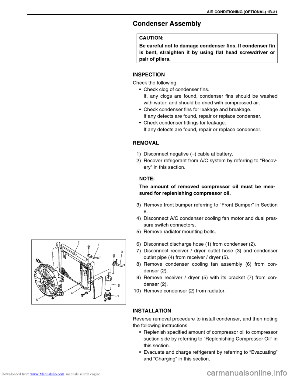
6) Disconnect discharge hose (1) from condenser (2).
7) Disconnect receiver / dryer outlet hose (3) and condenser
outlet pipe (4) from receiver / dryer (5).
8) Remove condenser cooling fan assembly (6) from con-
denser (2).
9) Remove receiver / dryer (5) with its bracket (7) from con-
denser (2).
10) Remove condenser (2) from radiator.
INSTALLATION
Reverse removal procedure to install condenser, and then noting
the following instructions.
Replenish specified amount of compressor oil to compressor
suction side by referring to “Replenishing Compressor Oil” in
this section.
Evacuate and charge refrigerant by referring to “Evacuating”
and “Charging” in this section. CAUTION:
Be careful not to damage condenser fins. If condenser fin
is bent, straighten it by using flat head screwdriver or
pair of pliers.
NOTE:
The amount of removed compressor oil must be mea-
sured for replenishing compressor oil.
Page 96 of 687

Downloaded from www.Manualslib.com manuals search engine AIR CONDITIONING (OPTIONAL) 1B-35
3) Drain engine coolant and disconnect heater hoses (1) from
heater unit.
4) Disable air bag system referring to “Disabling Air Bag Sys-
tem” in Section 10B (if equipped).
5) Remove attaching bolt (1).
6) Disconnect suction hose (2) and receiver / dryer outlet pipe
(3) from expansion valve (4).
7) Remove instrument panel referring to “Instrument Panel” in
Section 9.
8) Remove cooling unit (1) with heater unit (2) from vehicle
body.
9) Remove cooling unit (1) from heater unit (2).
INSPECTION
Check the following.
Check clog of A/C evaporator fins.
If any clogs are found, A/C evaporator fins should be
washed with water, and should be dried with compressed
air.
Check A/C evaporator fins for leakage and breakage.
If any defects are found, repair or replace A/C evaporator.
Check A/C evaporator fittings for leakage.
If any defects are found, repair or replace A/C evaporator.
Page 103 of 687

Downloaded from www.Manualslib.com manuals search engine 1B-42 AIR CONDITIONING (OPTIONAL)
INSPECTION
Check clutch plate and clutch pulley for leaks of compressor
oil.
Check clutch bearing of compressor pulley for noise, wear
and grease leakage.
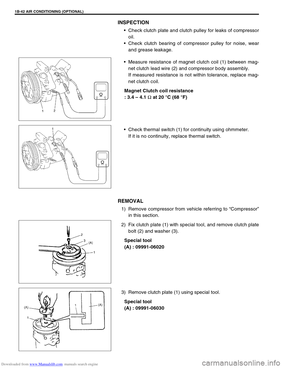
Measure resistance of magnet clutch coil (1) between mag-
net clutch lead wire (2) and compressor body assembly.
If measured resistance is not within tolerance, replace mag-
net clutch coil.
Magnet Clutch coil resistance
: 3.4 – 4.1
Ω at 20 °C (68 °F)
Check thermal switch (1) for continuity using ohmmeter.
If it is no continuity, replace thermal switch.
REMOVAL
1) Remove compressor from vehicle referring to “Compressor”
in this section.
2) Fix clutch plate (1) with special tool, and remove clutch plate
bolt (2) and washer (3).
Special tool
(A) : 09991-06020
3) Remove clutch plate (1) using special tool.
Special tool
(A) : 09991-06030