2005 SUZUKI JIMNY leak
[x] Cancel search: leakPage 630 of 687

Downloaded from www.Manualslib.com manuals search engine ENGINE AND EMISSION CONTROL SYSTEM 6E-25
INSTALLATION
For installation, reverse removal procedure and note following
precautions.
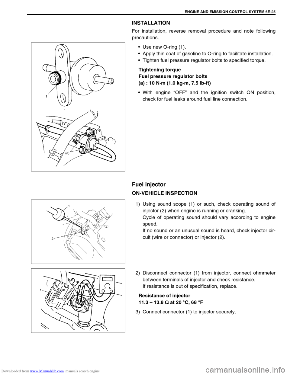
Use new O-ring (1).
Apply thin coat of gasoline to O-ring to facilitate installation.
Tighten fuel pressure regulator bolts to specified torque.
Tightening torque
Fuel pressure regulator bolts
(a) : 10 N·m (1.0 kg-m, 7.5 lb-ft)
With engine “OFF” and the ignition switch ON position,
check for fuel leaks around fuel line connection.
Fuel injector
ON-VEHICLE INSPECTION
1) Using sound scope (1) or such, check operating sound of
injector (2) when engine is running or cranking.
Cycle of operating sound should vary according to engine
speed.
If no sound or an unusual sound is heard, check injector cir-
cuit (wire or connector) or injector (2).
2) Disconnect connector (1) from injector, connect ohmmeter
between terminals of injector and check resistance.
If resistance is out of specification, replace.
Resistance of injector
11.3 – 13.8
Ω
ΩΩ Ω at 20 °C, 68 °F
3) Connect connector (1) to injector securely.
Page 632 of 687

Downloaded from www.Manualslib.com manuals search engine ENGINE AND EMISSION CONTROL SYSTEM 6E-27
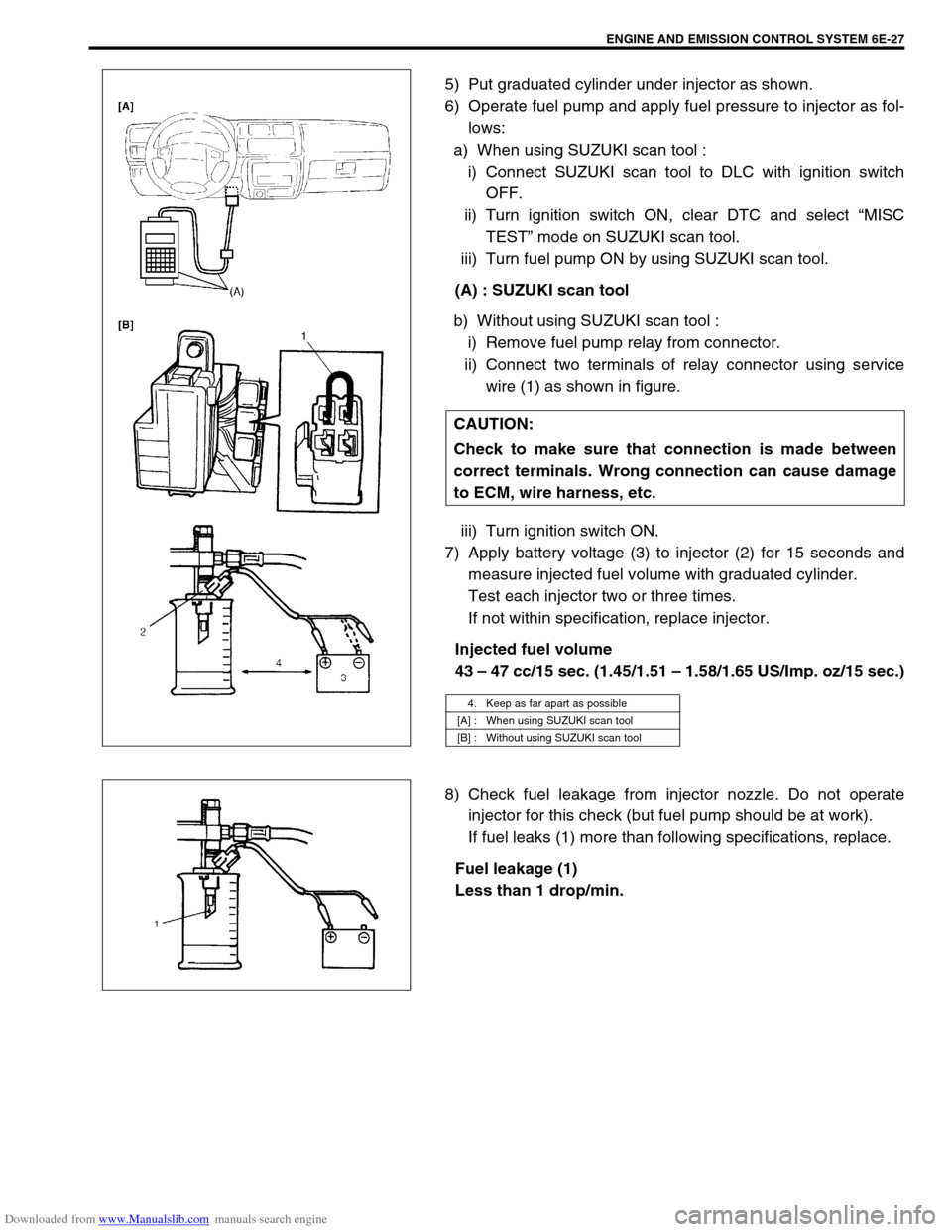
5) Put graduated cylinder under injector as shown.
6) Operate fuel pump and apply fuel pressure to injector as fol-
lows:
a) When using SUZUKI scan tool :
i) Connect SUZUKI scan tool to DLC with ignition switch
OFF.
ii) Turn ignition switch ON, clear DTC and select “MISC
TEST” mode on SUZUKI scan tool.
iii) Turn fuel pump ON by using SUZUKI scan tool.
(A) : SUZUKI scan tool
b) Without using SUZUKI scan tool :
i) Remove fuel pump relay from connector.
ii) Connect two terminals of relay connector using service
wire (1) as shown in figure.
iii) Turn ignition switch ON.
7) Apply battery voltage (3) to injector (2) for 15 seconds and
measure injected fuel volume with graduated cylinder.
Test each injector two or three times.
If not within specification, replace injector.
Injected fuel volume
43 – 47 cc/15 sec. (1.45/1.51 – 1.58/1.65 US/Imp. oz/15 sec.)
8) Check fuel leakage from injector nozzle. Do not operate
injector for this check (but fuel pump should be at work).
If fuel leaks (1) more than following specifications, replace.
Fuel leakage (1)
Less than 1 drop/min. CAUTION:
Check to make sure that connection is made between
correct terminals. Wrong connection can cause damage
to ECM, wire harness, etc.
4. Keep as far apart as possible
[A] : When using SUZUKI scan tool
[B] : Without using SUZUKI scan tool
Page 633 of 687

Downloaded from www.Manualslib.com manuals search engine 6E-28 ENGINE AND EMISSION CONTROL SYSTEM
INSTALLATION
For installation, reverse removal procedure and note following
precautions.
Replace injector O-ring (1) with new one using care not to
damage it.
Check if cushion (2) is scored or damaged. If it is, replace
with new one.
Apply thin coat of fuel to O-rings (1) and then install injectors
(3) into delivery pipe (4) and intake manifold.
Make sure that injectors (3) rotate smoothly (6). If not, proba-
ble cause is incorrect installation of O-ring (1). Replace O-
ring (1) with new one.
Tighten delivery pipe bolts (5) and make sure that injectors
(3) rotate smoothly (6).
After installation, with engine “OFF” and ignition switch “ON”,
check for fuel leaks around fuel line connection.
Page 639 of 687

Downloaded from www.Manualslib.com manuals search engine 6E-34 ENGINE AND EMISSION CONTROL SYSTEM
1) Disconnect negative cable at battery.
2) For sensor-1, remove exhaust manifold cover (1) and dis-
connect connector of heated oxygen sensor and release its
wire harness from clamps.
3) For sensor-2, disconnect connector of heated oxygen sensor
and release its wire harness from clamp. Hoist vehicle and
then remove exhaust No.1 pipe covers (3).
4) Remove heated oxygen sensor (2) from exhaust manifold or
exhaust No.1 pipe.
INSTALLATION
Reverse removal procedure noting the following.
Tighten heated oxygen sensor (2) to specified torque.
Tightening torque
Heated oxygen sensor (a) : 45 N·m (4.5 kg-m, 32.5 lb-ft)
Connect connector of heated oxygen sensor (2) and clamp
wire harness securely.
After installing heated oxygen sensor (2), start engine and
check that no exhaust gas leakage exists.
Camshaft position sensor
INSPECTION
Check camshaft position sensor referring to “DTC P0340 (No. 15)
Diag. Flow Table” in Section 6. If malfunction is found, replace.
REMOVAL
1) Disconnect negative cable at battery.
2) Disconnect connector from camshaft position sensor.
3) Remove camshaft position sensor from cylinder head.
INSTALLATION
1) Check that O-ring is free from damage.
2) Check that camshaft position sensor and signal rotor tooth
are free from any metal particles and damage.
3) Install camshaft position sensor to sensor case.
Tightening torque
Camshaft position sensor bolt
(a) : 10 N·m (1.0 kg-m, 7.5 lb-ft)
4) Connect connector to it securely.
5) Connect negative cable to battery.
[A] : HO2S-1
[B] : HO2S-2
Page 645 of 687

Downloaded from www.Manualslib.com manuals search engine 6E-40 ENGINE AND EMISSION CONTROL SYSTEM
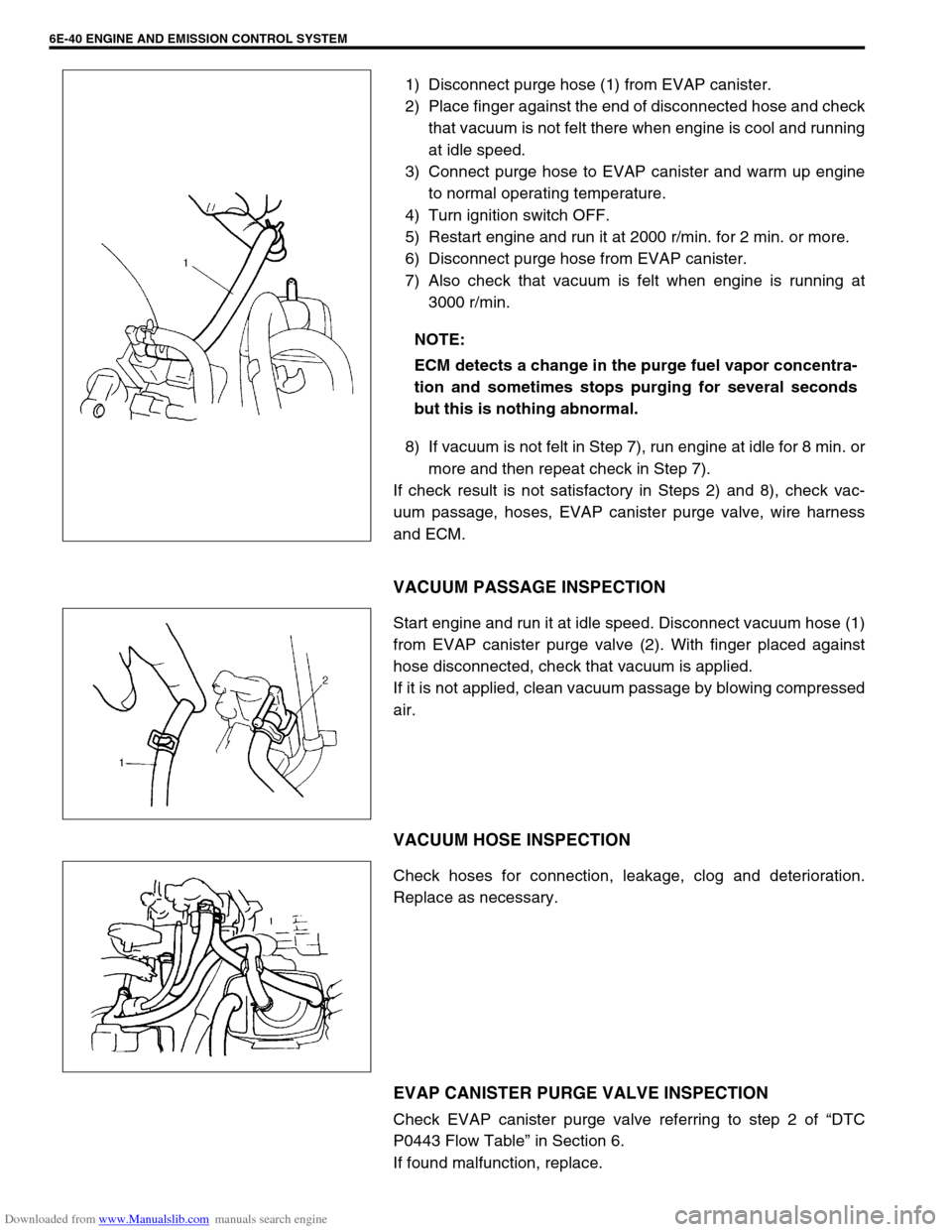
1) Disconnect purge hose (1) from EVAP canister.
2) Place finger against the end of disconnected hose and check
that vacuum is not felt there when engine is cool and running
at idle speed.
3) Connect purge hose to EVAP canister and warm up engine
to normal operating temperature.
4) Turn ignition switch OFF.
5) Restart engine and run it at 2000 r/min. for 2 min. or more.
6) Disconnect purge hose from EVAP canister.
7) Also check that vacuum is felt when engine is running at
3000 r/min.
8) If vacuum is not felt in Step 7), run engine at idle for 8 min. or
more and then repeat check in Step 7).
If check result is not satisfactory in Steps 2) and 8), check vac-
uum passage, hoses, EVAP canister purge valve, wire harness
and ECM.
VACUUM PASSAGE INSPECTION
Start engine and run it at idle speed. Disconnect vacuum hose (1)
from EVAP canister purge valve (2). With finger placed against
hose disconnected, check that vacuum is applied.
If it is not applied, clean vacuum passage by blowing compressed
air.
VACUUM HOSE INSPECTION
Check hoses for connection, leakage, clog and deterioration.
Replace as necessary.
EVAP CANISTER PURGE VALVE INSPECTION
Check EVAP canister purge valve referring to step 2 of “DTC
P0443 Flow Table” in Section 6.
If found malfunction, replace.NOTE:
ECM detects a change in the purge fuel vapor concentra-
tion and sometimes stops purging for several seconds
but this is nothing abnormal.
Page 646 of 687

Downloaded from www.Manualslib.com manuals search engine ENGINE AND EMISSION CONTROL SYSTEM 6E-41
EVAP CANISTER INSPECTION
1) Check outside of EVAP canister visually.
2) Disconnect vacuum hoses from EVAP canister.
3) Check that there should be no restriction of flow through
purge pipe (1) and air pipe (2) when air is blown (4) into tank
pipe (3).
If any faulty condition is found in above inspection replace.
PCV system
PCV HOSE INSPECTION
Check hoses for connection, leakage, clog and deterioration.
Replace as necessary.
PCV VALVE INSPECTION
1) Disconnect PCV valve (1) from cylinder head cover and
install plug to head cover hole.
2) Run engine at idle.
3) Place your finger over end of PCV valve (1) to check for vac-
uum. If there is no vacuum, check for clogged valve.
Replace as necessary. WARNING:
DO NOT SUCK nozzles on EVAP canister. Fuel vapor
inside EVAP canister is harmful.
NOTE:
Be sure to check that there is no obstruction in PCV
valve or its hoses before checking IAC duty, for
obstructed PCV valve or hose hampers its accurate
adjustment.
Page 686 of 687

Downloaded from www.Manualslib.com manuals search engine EXHAUST SYSTEM 6K-1
6F1
6F2
6G
6H
7D
7E
7F
7D
7E
7F
8A
8B
8C
8D
8E
9
7A1
6K
7C1
SECTION 6K
EXHAUST SYSTEM
CONTENTS
General Description ........................................6K-1
Maintenance ....................................................6K-1On-Vehicle Service ......................................... 6K-2
Exhaust Manifold .......................................... 6K-2
Exhaust Pipe ................................................. 6K-2
General Description
The exhaust system of this vehicle consists of the exhaust manifold, exhaust center pipe, muffler, seals, etc.
The catalytic converter is an emission control device added to the exhaust system to lower the level of Hydro-
carbon (HC), Carbon Monoxide (CO) and Oxides of Nitrogen (NOx) pollutants in the exhaust gas. The catalyst
in the catalytic converter is of “Three way” type.
Maintenance
At every interval of periodic maintenance service, and when vehicle is raised for other service, check exhaust
system as follows:
Check rubber mountings for damage, deterioration and out of position.
Check exhaust system for leakage, loose connection, dent and damage.
If bolts or nuts are loosened, tighten them to specified torque. Refer to “Components” in this section.
Check nearby body areas for damaged, missing, or mispositioned part, open seam, hole, loose connection
or any other defect which could permit exhaust fumes to seep into vehicle.
Make sure that exhaust system components have enough clearance from underbody to avoid overheating
and possible damage to passenger compartment carpet.
Any defect should be fixed at once. NOTE:
Whether following parts are used in the particular vehicle or not depends on specification. Be sure to
bear this in mind when performing service work.
Three-Way Catalytic Converter (TWC)
CAUTION:
Be sure to use UNLEADED FUEL for the catalytic converter equipped vehicle. Use of LEADED FUEL
will affect performance of the catalytic converter adversely to a great extent.
WARNING:
To avoid danger of being burned, do not touch exhaust system when system is hot.
Any service on exhaust system should be performed when system is cool.