Page 642 of 687

Downloaded from www.Manualslib.com manuals search engine ENGINE AND EMISSION CONTROL SYSTEM 6E-37
Fuel cut operation
INSPECTION
1) Warm up engine to normal operating temperature.
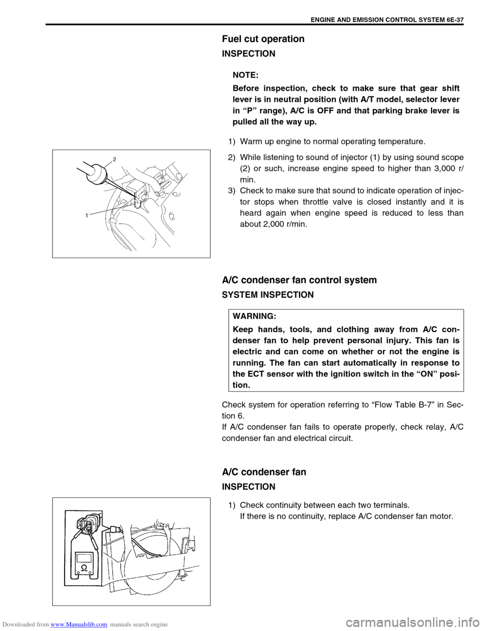
2) While listening to sound of injector (1) by using sound scope
(2) or such, increase engine speed to higher than 3,000 r/
min.
3) Check to make sure that sound to indicate operation of injec-
tor stops when throttle valve is closed instantly and it is
heard again when engine speed is reduced to less than
about 2,000 r/min.
A/C condenser fan control system
SYSTEM INSPECTION
Check system for operation referring to “Flow Table B-7” in Sec-
tion 6.
If A/C condenser fan fails to operate properly, check relay, A/C
condenser fan and electrical circuit.
A/C condenser fan
INSPECTION
1) Check continuity between each two terminals.
If there is no continuity, replace A/C condenser fan motor. NOTE:
Before inspection, check to make sure that gear shift
lever is in neutral position (with A/T model, selector lever
in “P” range), A/C is OFF and that parking brake lever is
pulled all the way up.
WARNING:
Keep hands, tools, and clothing away from A/C con-
denser fan to help prevent personal injury. This fan is
electric and can come on whether or not the engine is
running. The fan can start automatically in response to
the ECT sensor with the ignition switch in the “ON” posi-
tion.
Page 643 of 687

Downloaded from www.Manualslib.com manuals search engine 6E-38 ENGINE AND EMISSION CONTROL SYSTEM
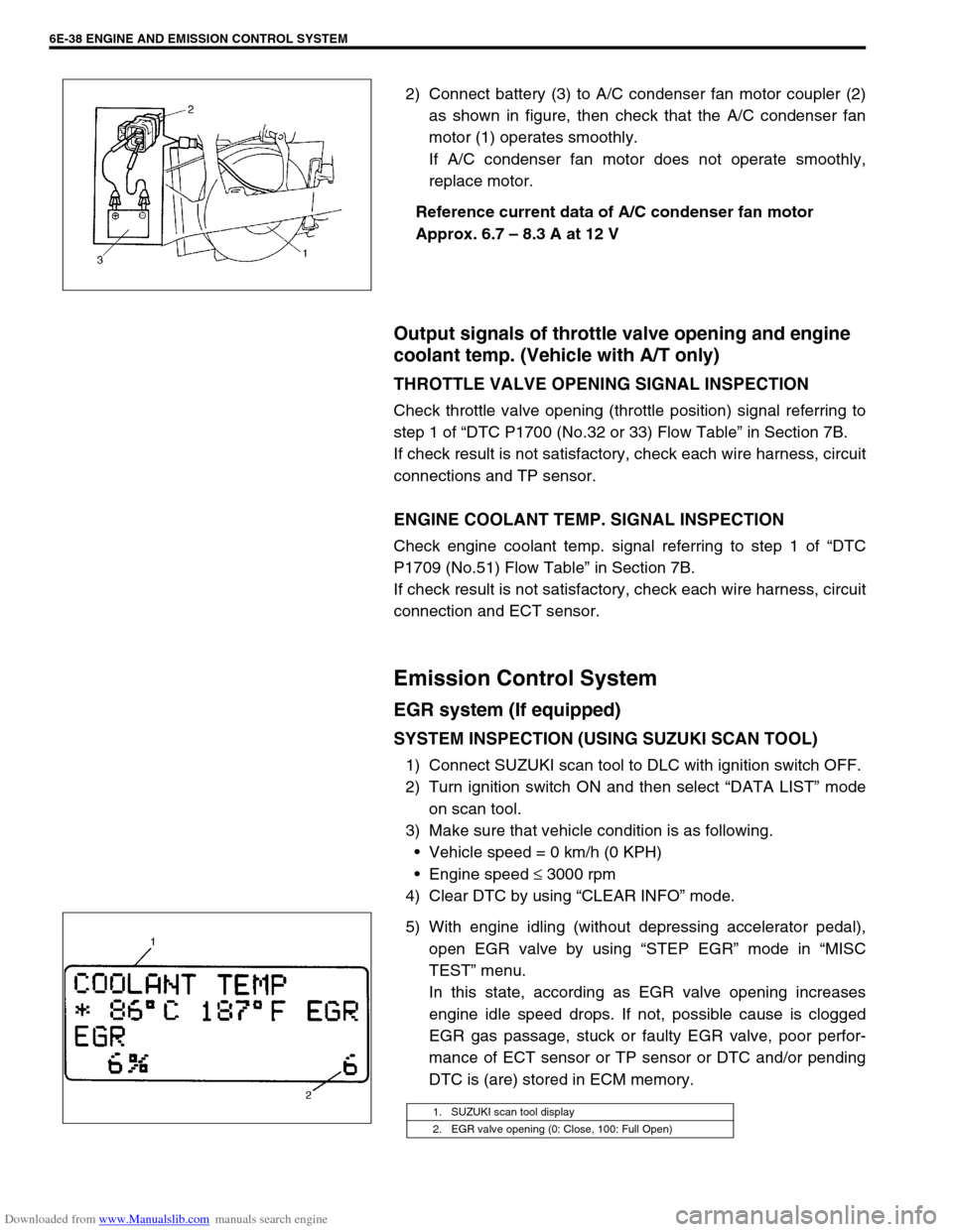
2) Connect battery (3) to A/C condenser fan motor coupler (2)
as shown in figure, then check that the A/C condenser fan
motor (1) operates smoothly.
If A/C condenser fan motor does not operate smoothly,
replace motor.
Reference current data of A/C condenser fan motor
Approx. 6.7 – 8.3 A at 12 V
Output signals of throttle valve opening and engine
coolant temp. (Vehicle with A/T only)
THROTTLE VALVE OPENING SIGNAL INSPECTION
Check throttle valve opening (throttle position) signal referring to
step 1 of “DTC P1700 (No.32 or 33) Flow Table” in Section 7B.
If check result is not satisfactory, check each wire harness, circuit
connections and TP sensor.
ENGINE COOLANT TEMP. SIGNAL INSPECTION
Check engine coolant temp. signal referring to step 1 of “DTC
P1709 (No.51) Flow Table” in Section 7B.
If check result is not satisfactory, check each wire harness, circuit
connection and ECT sensor.
Emission Control System
EGR system (If equipped)
SYSTEM INSPECTION (USING SUZUKI SCAN TOOL)
1) Connect SUZUKI scan tool to DLC with ignition switch OFF.
2) Turn ignition switch ON and then select “DATA LIST” mode
on scan tool.
3) Make sure that vehicle condition is as following.
Vehicle speed = 0 km/h (0 KPH)
Engine speed ≤ 3000 rpm
4) Clear DTC by using “CLEAR INFO” mode.
5) With engine idling (without depressing accelerator pedal),
open EGR valve by using “STEP EGR” mode in “MISC
TEST” menu.
In this state, according as EGR valve opening increases
engine idle speed drops. If not, possible cause is clogged
EGR gas passage, stuck or faulty EGR valve, poor perfor-
mance of ECT sensor or TP sensor or DTC and/or pending
DTC is (are) stored in ECM memory.
1. SUZUKI scan tool display
2. EGR valve opening (0: Close, 100: Full Open)
Page 657 of 687

Downloaded from www.Manualslib.com manuals search engine 6F-8 IGNITION SYSTEM (ELECTRONIC IGNITION SYSTEM)
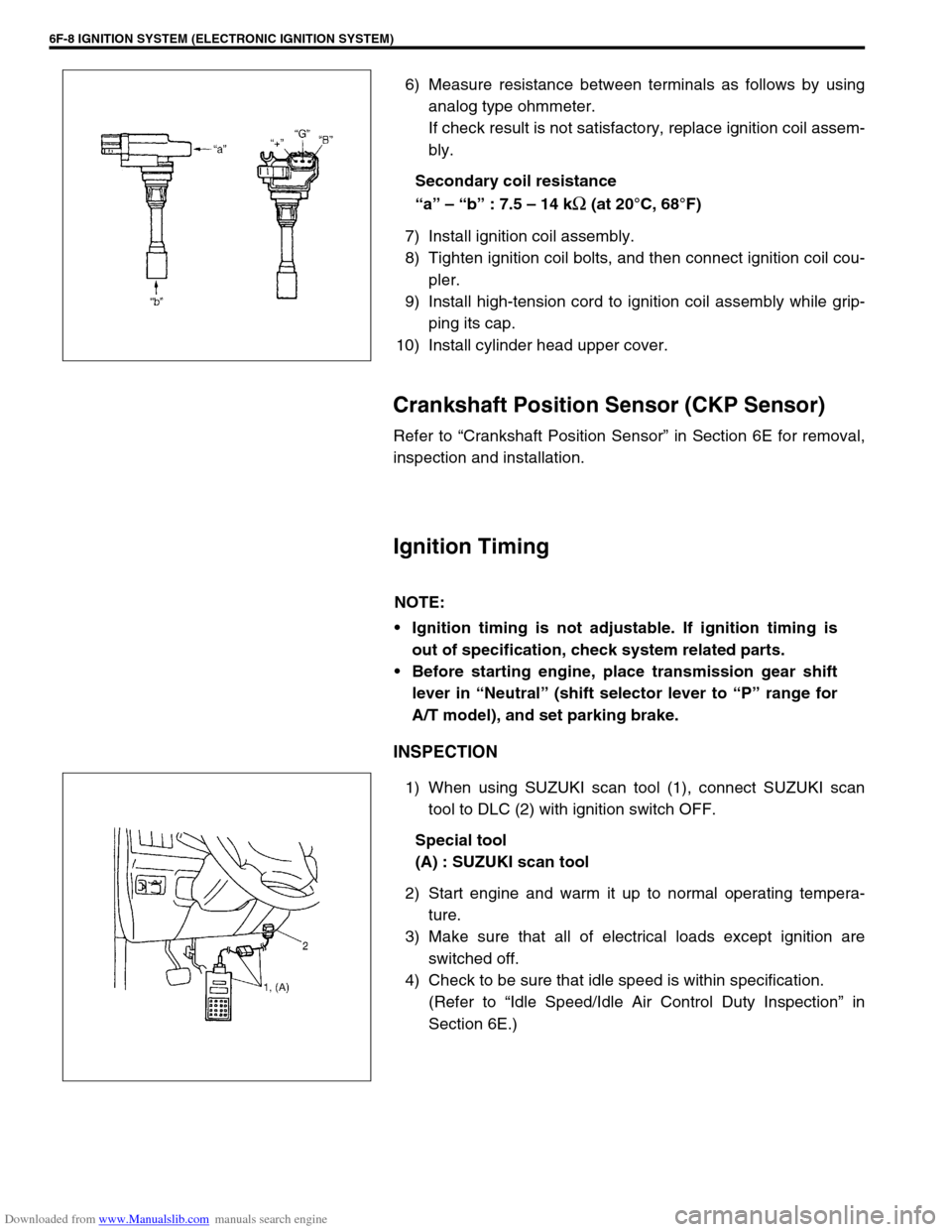
6) Measure resistance between terminals as follows by using
analog type ohmmeter.
If check result is not satisfactory, replace ignition coil assem-
bly.
Secondary coil resistance
“a” – “b” : 7.5 – 14 k
Ω (at 20°C, 68°F)
7) Install ignition coil assembly.
8) Tighten ignition coil bolts, and then connect ignition coil cou-
pler.
9) Install high-tension cord to ignition coil assembly while grip-
ping its cap.
10) Install cylinder head upper cover.
Crankshaft Position Sensor (CKP Sensor)
Refer to “Crankshaft Position Sensor” in Section 6E for removal,
inspection and installation.
Ignition Timing
INSPECTION
1) When using SUZUKI scan tool (1), connect SUZUKI scan
tool to DLC (2) with ignition switch OFF.
Special tool
(A) : SUZUKI scan tool
2) Start engine and warm it up to normal operating tempera-
ture.
3) Make sure that all of electrical loads except ignition are
switched off.
4) Check to be sure that idle speed is within specification.
(Refer to “Idle Speed/Idle Air Control Duty Inspection” in
Section 6E.)
NOTE:
Ignition timing is not adjustable. If ignition timing is
out of specification, check system related parts.
Before starting engine, place transmission gear shift
lever in “Neutral” (shift selector lever to “P” range for
A/T model), and set parking brake.
Page 658 of 687

Downloaded from www.Manualslib.com manuals search engine IGNITION SYSTEM (ELECTRONIC IGNITION SYSTEM 6F-9
5) Fix ignition timing to initial one as follows.
a) When using SUZUKI scan tool:
Select “MISC” mode on SUZUKI scan tool and fix ignition
timing to initial one.
b) Without using SUZUKI scan tool: (vehicle without immobi-
lizer indicator lamp)
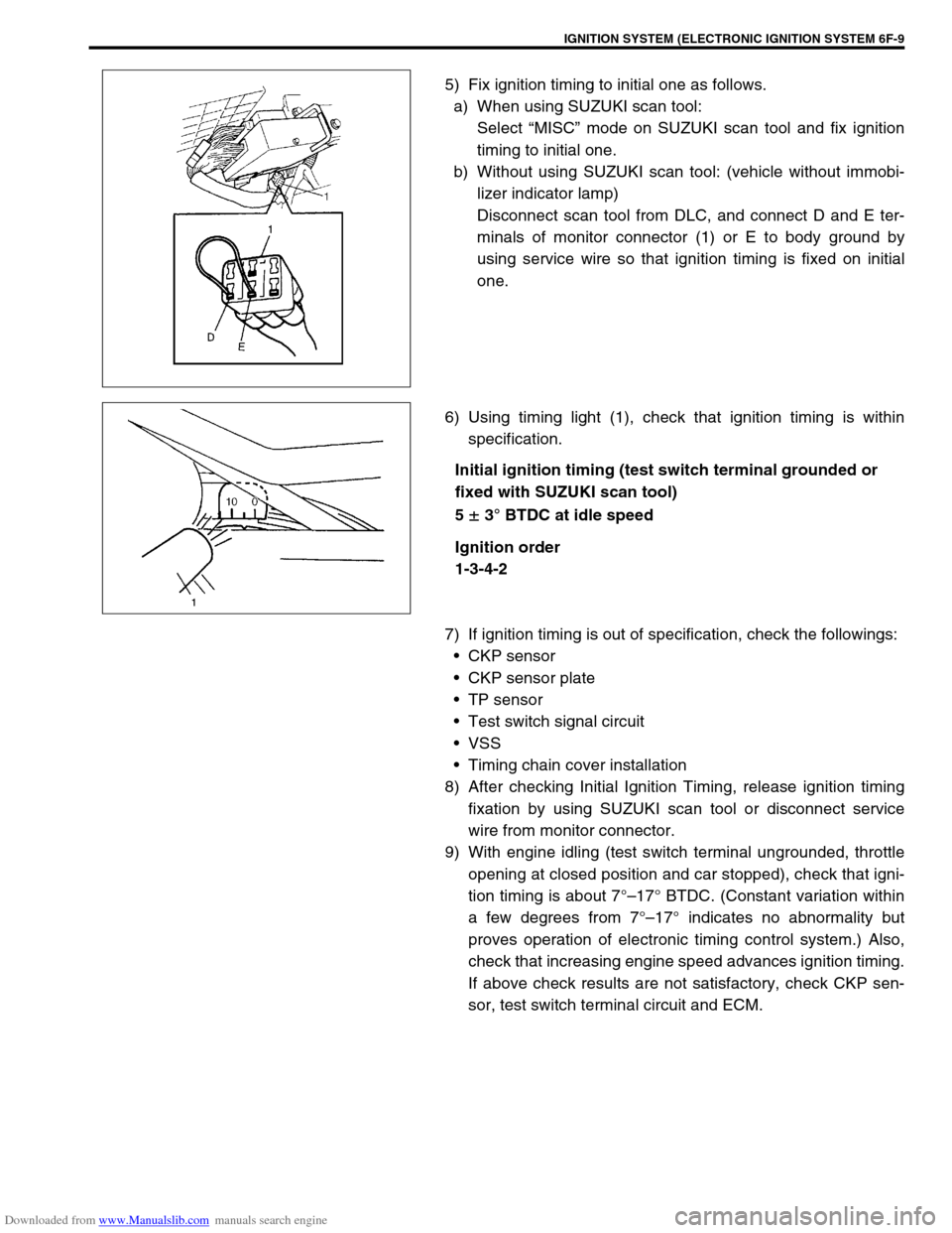
Disconnect scan tool from DLC, and connect D and E ter-
minals of monitor connector (1) or E to body ground by
using service wire so that ignition timing is fixed on initial
one.
6) Using timing light (1), check that ignition timing is within
specification.
Initial ignition timing (test switch terminal grounded or
fixed with SUZUKI scan tool)
5
± 3° BTDC at idle speed
Ignition order
1-3-4-2
7) If ignition timing is out of specification, check the followings:
CKP sensor
CKP sensor plate
TP sensor
Test switch signal circuit
VSS
Timing chain cover installation
8) After checking Initial Ignition Timing, release ignition timing
fixation by using SUZUKI scan tool or disconnect service
wire from monitor connector.
9) With engine idling (test switch terminal ungrounded, throttle
opening at closed position and car stopped), check that igni-
tion timing is about 7°–17° BTDC. (Constant variation within
a few degrees from 7°–17° indicates no abnormality but
proves operation of electronic timing control system.) Also,
check that increasing engine speed advances ignition timing.
If above check results are not satisfactory, check CKP sen-
sor, test switch terminal circuit and ECM.