Page 474 of 687
Downloaded from www.Manualslib.com manuals search engine ENGINE GENERAL INFORMATION AND DIAGNOSIS 6-117
Table B-5 A/C Signal Circuits Check (Vehicle with A/C)
1. A/C compressor magnet clutch 4. A/C condenser fan 7. Evaporator temp. sensor
2. A/C switch 5. Refrigerant pressure switch [A] : Case of TYPE A is shown (See NOTE)
3. Blower fan 6. ECT sensor [B] : Case of TYPE B is shown (See NOTE)
NOTE:
For TYPE A and TYPE B, refer to the NOTE in “ECM Terminal Voltage Values Table” for applicable
model.
Page 475 of 687
Downloaded from www.Manualslib.com manuals search engine 6-118 ENGINE GENERAL INFORMATION AND DIAGNOSIS
INSPECTION
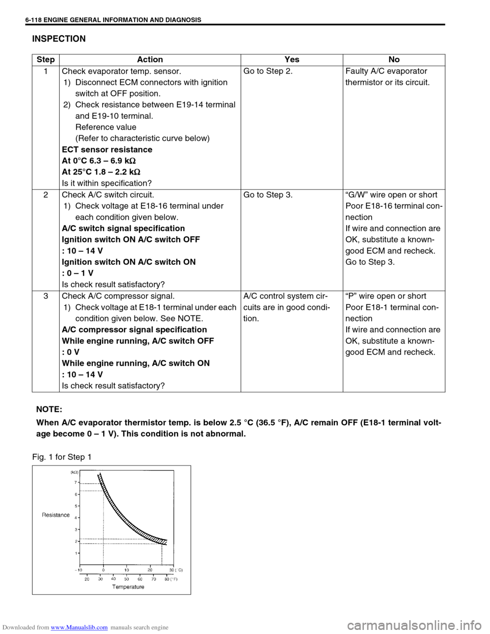
Fig. 1 for Step 1Step Action Yes No
1 Check evaporator temp. sensor.
1) Disconnect ECM connectors with ignition
switch at OFF position.
2) Check resistance between E19-14 terminal
and E19-10 terminal.
Reference value
(Refer to characteristic curve below)
ECT sensor resistance
At 0°C 6.3 – 6.9 k
Ω
ΩΩ Ω
At 25°C 1.8 – 2.2 k
Ω
ΩΩ Ω
Is it within specification?Go to Step 2. Faulty A/C evaporator
thermistor or its circuit.
2 Check A/C switch circuit.
1) Check voltage at E18-16 terminal under
each condition given below.
A/C switch signal specification
Ignition switch ON A/C switch OFF
: 10 – 14 V
Ignition switch ON A/C switch ON
: 0 – 1 V
Is check result satisfactory?Go to Step 3.“G/W” wire open or short
Poor E18-16 terminal con-
nection
If wire and connection are
OK, substitute a known-
good ECM and recheck.
Go to Step 3.
3 Check A/C compressor signal.
1) Check voltage at E18-1 terminal under each
condition given below. See NOTE.
A/C compressor signal specification
While engine running, A/C switch OFF
: 0 V
While engine running, A/C switch ON
: 10 – 14 V
Is check result satisfactory?A/C control system cir-
cuits are in good condi-
tion.“P” wire open or short
Poor E18-1 terminal con-
nection
If wire and connection are
OK, substitute a known-
good ECM and recheck.
NOTE:
When A/C evaporator thermistor temp. is below 2.5 °C (36.5 °F), A/C remain OFF (E18-1 terminal volt-
age become 0 – 1 V). This condition is not abnormal.
Page 499 of 687
Downloaded from www.Manualslib.com manuals search engine 6A1-18 ENGINE MECHANICAL (M13 ENGINE)
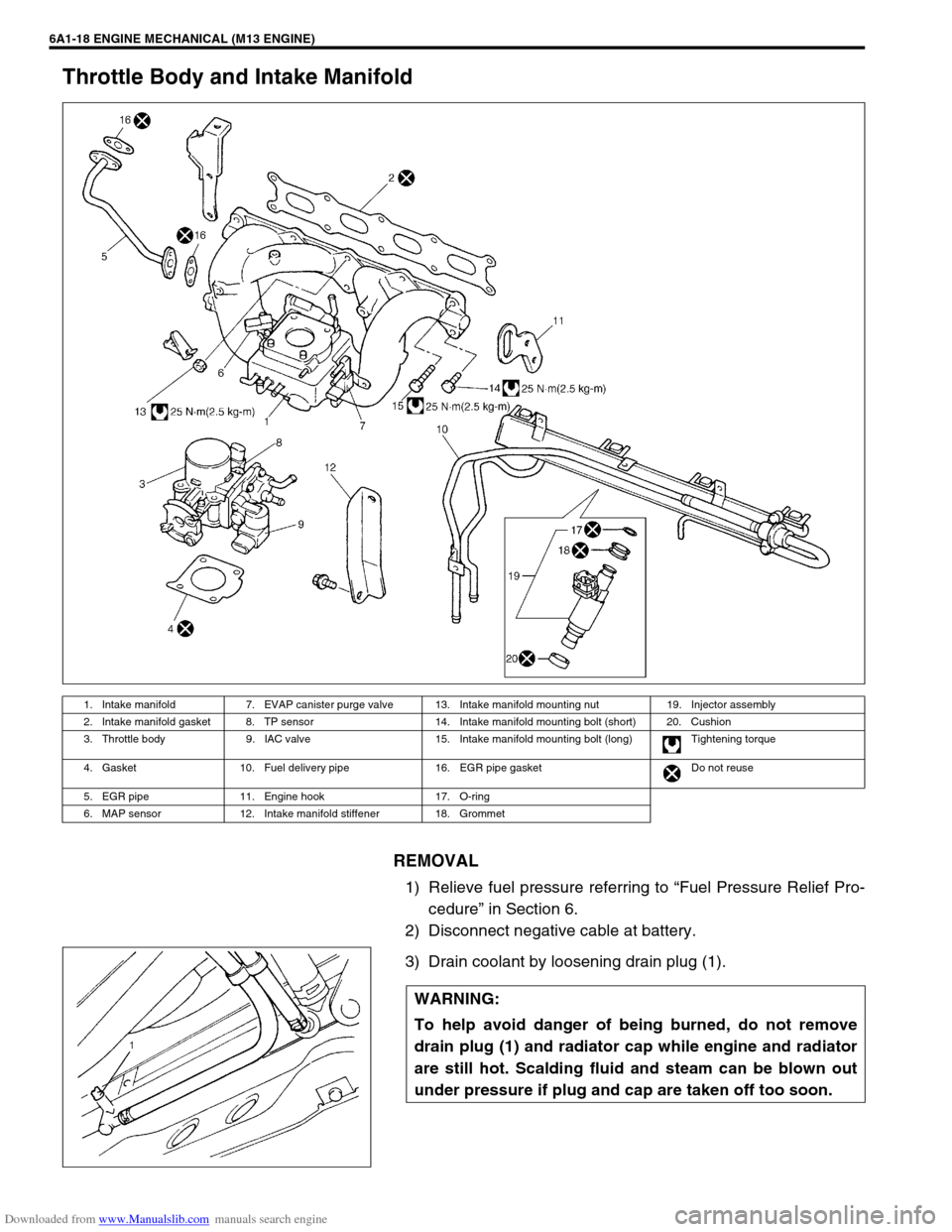
Throttle Body and Intake Manifold
REMOVAL
1) Relieve fuel pressure referring to “Fuel Pressure Relief Pro-
cedure” in Section 6.
2) Disconnect negative cable at battery.
3) Drain coolant by loosening drain plug (1).
1. Intake manifold 7. EVAP canister purge valve 13. Intake manifold mounting nut 19. Injector assembly
2. Intake manifold gasket 8. TP sensor 14. Intake manifold mounting bolt (short) 20. Cushion
3. Throttle body 9. IAC valve 15. Intake manifold mounting bolt (long) Tightening torque
4. Gasket 10. Fuel delivery pipe 16. EGR pipe gasket Do not reuse
5. EGR pipe 11. Engine hook 17. O-ring
6. MAP sensor 12. Intake manifold stiffener 18. Grommet
WARNING:
To help avoid danger of being burned, do not remove
drain plug (1) and radiator cap while engine and radiator
are still hot. Scalding fluid and steam can be blown out
under pressure if plug and cap are taken off too soon.
Page 500 of 687
Downloaded from www.Manualslib.com manuals search engine ENGINE MECHANICAL (M13 ENGINE) 6A1-19
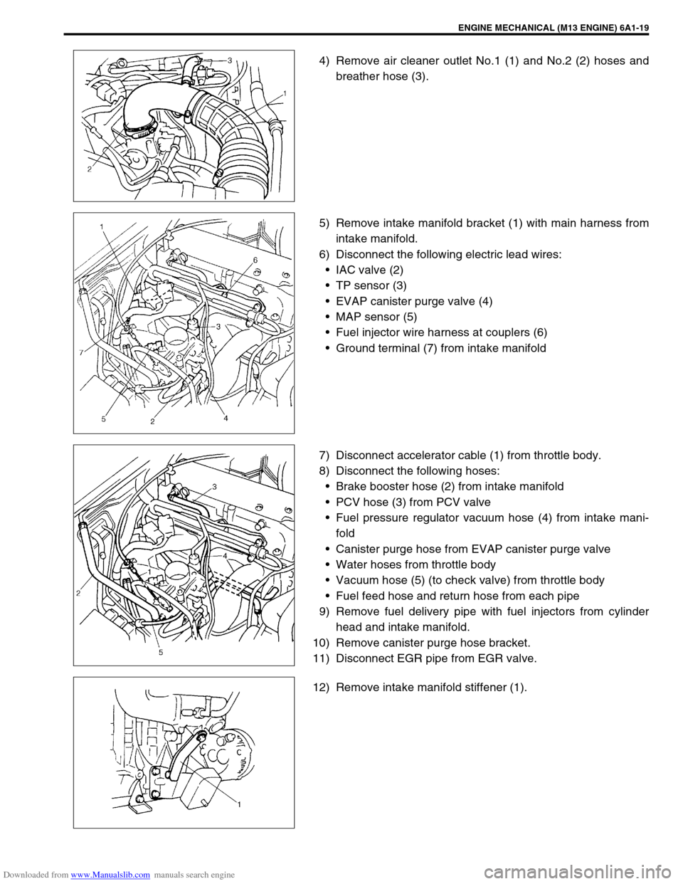
4) Remove air cleaner outlet No.1 (1) and No.2 (2) hoses and
breather hose (3).
5) Remove intake manifold bracket (1) with main harness from
intake manifold.
6) Disconnect the following electric lead wires:
IAC valve (2)
TP sensor (3)
EVAP canister purge valve (4)
MAP sensor (5)
Fuel injector wire harness at couplers (6)
Ground terminal (7) from intake manifold
7) Disconnect accelerator cable (1) from throttle body.
8) Disconnect the following hoses:
Brake booster hose (2) from intake manifold
PCV hose (3) from PCV valve
Fuel pressure regulator vacuum hose (4) from intake mani-
fold
Canister purge hose from EVAP canister purge valve
Water hoses from throttle body
Vacuum hose (5) (to check valve) from throttle body
Fuel feed hose and return hose from each pipe
9) Remove fuel delivery pipe with fuel injectors from cylinder
head and intake manifold.
10) Remove canister purge hose bracket.
11) Disconnect EGR pipe from EGR valve.
12) Remove intake manifold stiffener (1).
Page 530 of 687
Downloaded from www.Manualslib.com manuals search engine ENGINE MECHANICAL (M13 ENGINE) 6A1-49
REMOVAL
1) Relieve fuel pressure referring to “Fuel Pressure Relief Pro-
cedure” in Section 6.
2) Disconnect negative cable at battery.
3) Drain engine oil.
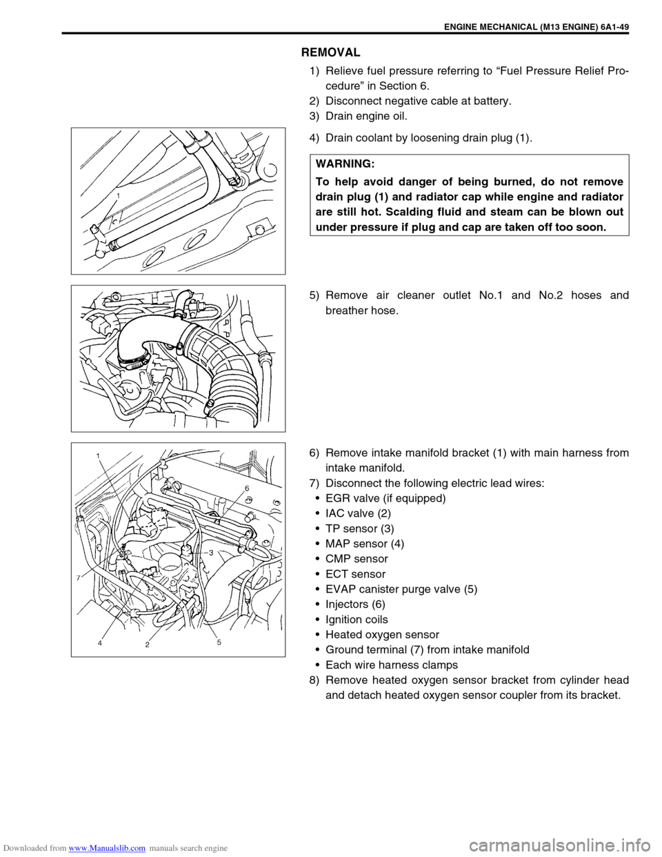
4) Drain coolant by loosening drain plug (1).
5) Remove air cleaner outlet No.1 and No.2 hoses and
breather hose.
6) Remove intake manifold bracket (1) with main harness from
intake manifold.
7) Disconnect the following electric lead wires:
EGR valve (if equipped)
IAC valve (2)
TP sensor (3)
MAP sensor (4)
CMP sensor
ECT sensor
EVAP canister purge valve (5)
Injectors (6)
Ignition coils
Heated oxygen sensor
Ground terminal (7) from intake manifold
Each wire harness clamps
8) Remove heated oxygen sensor bracket from cylinder head
and detach heated oxygen sensor coupler from its bracket. WARNING:
To help avoid danger of being burned, do not remove
drain plug (1) and radiator cap while engine and radiator
are still hot. Scalding fluid and steam can be blown out
under pressure if plug and cap are taken off too soon.
Page 531 of 687
Downloaded from www.Manualslib.com manuals search engine 6A1-50 ENGINE MECHANICAL (M13 ENGINE)
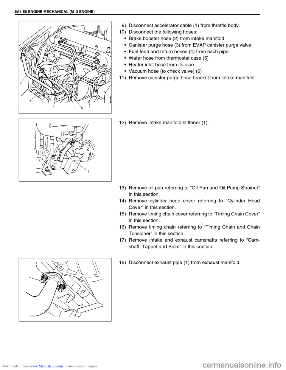
9) Disconnect accelerator cable (1) from throttle body.
10) Disconnect the following hoses:
Brake booster hose (2) from intake manifold
Canister purge hose (3) from EVAP canister purge valve
Fuel feed and return hoses (4) from each pipe
Water hose from thermostat case (5)
Heater inlet hose from its pipe
Vacuum hose (to check valve) (6)
11) Remove canister purge hose bracket from intake manifold.
12) Remove intake manifold stiffener (1).
13) Remove oil pan referring to “Oil Pan and Oil Pump Strainer”
in this section.
14) Remove cylinder head cover referring to “Cylinder Head
Cover” in this section.
15) Remove timing chain cover referring to “Timing Chain Cover”
in this section.
16) Remove timing chain referring to “Timing Chain and Chain
Tensioner” in this section.
17) Remove intake and exhaust camshafts referring to “Cam-
shaft, Tappet and Shim” in this section.
18) Disconnect exhaust pipe (1) from exhaust manifold.
Page 555 of 687
Downloaded from www.Manualslib.com manuals search engine 6A1-74 ENGINE MECHANICAL (M13 ENGINE)
a) For right hand steering vehicle:
With hose connected, detach A/C compressor from its
bracket.
b) For left hand steering vehicle:
i) Recover refrigerant from refrigeration system using recov-
ery and recycling equipment.
ii) Disconnect magnet clutch lead wire.
iii) Remove suction pipe and disconnect discharge pipe from
A/C compressor.
iv) Remove A/C compressor from its bracket.
When servicing above steps, refer to “Compressor” in Section 1B.
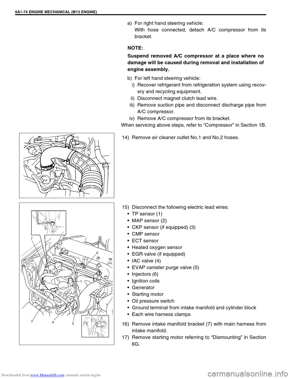
14) Remove air cleaner outlet No.1 and No.2 hoses.
15) Disconnect the following electric lead wires:
TP sensor (1)
MAP sensor (2)
CKP sensor (if equipped) (3)
CMP sensor
ECT sensor
Heated oxygen sensor
EGR valve (if equipped)
IAC valve (4)
EVAP canister purge valve (5)
Injectors (6)
Ignition coils
Generator
Starting motor
Oil pressure switch
Ground terminal from intake manifold and cylinder block
Each wire harness clamps
16) Remove intake manifold bracket (7) with main harness from
intake manifold.
17) Remove starting motor referring to “Dismounting” in Section
6G. NOTE:
Suspend removed A/C compressor at a place where no
damage will be caused during removal and installation of
engine assembly.
Page 556 of 687
Downloaded from www.Manualslib.com manuals search engine ENGINE MECHANICAL (M13 ENGINE) 6A1-75
18) Remove heated oxygen sensor bracket from cylinder head
and detach No.1 heated oxygen sensor coupler from its
bracket.
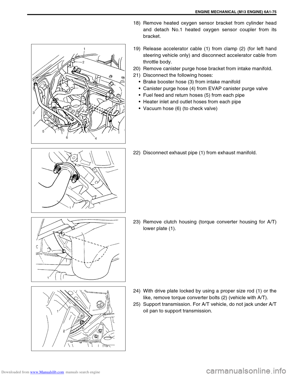
19) Release accelerator cable (1) from clamp (2) (for left hand
steering vehicle only) and disconnect accelerator cable from
throttle body.
20) Remove canister purge hose bracket from intake manifold.
21) Disconnect the following hoses:
Brake booster hose (3) from intake manifold
Canister purge hose (4) from EVAP canister purge valve
Fuel feed and return hoses (5) from each pipe
Heater inlet and outlet hoses from each pipe
Vacuum hose (6) (to check valve)
22) Disconnect exhaust pipe (1) from exhaust manifold.
23) Remove clutch housing (torque converter housing for A/T)
lower plate (1).
24) With drive plate locked by using a proper size rod (1) or the
like, remove torque converter bolts (2) (vehicle with A/T).
25) Support transmission. For A/T vehicle, do not jack under A/T
oil pan to support transmission.