2005 SUZUKI JIMNY KING PIN
[x] Cancel search: KING PINPage 323 of 687

Downloaded from www.Manualslib.com manuals search engine 5E-6 ANTILOCK BRAKE SYSTEM (ABS)
Diagnosis
To ensure that the trouble diagnosis is done accurately and smoothly, observe “Precautions in Diagnosing Trou-
bles” and follow “ABS Diagnostic Flow Table”.
Precaution in Diagnosing Troubles
If the vehicles was operated in any of the following ways, “ABS” warning lamp may light momentarily but this
does not indicate anything abnormal in ABS.
–The vehicle was driven with parking brake pulled.
–The vehicle was driven with brake dragging.
–The vehicle was stuck in mud, sand, etc.
–Wheel spin occurred while driving.
–Wheel(s) was rotated while the vehicle was jacked up.
Be sure to read “Precautions for Electronic Circuit Service” in Section 0A before inspection and observe
what is written there.
Be sure to use the trouble diagnosis procedure as described in the flow table. Failure to follow the flow table
may result in incorrect diagnosis. Some other diag. trouble code may be stored by mistake in the memory of
ABS control module during inspection.
ABS Diagnostic Flow Table
Refer to the following for the details of each step.
Step Action Yes No
1 Perform customer complaint analysis, problem symptom confir-
mation and diagnostic trouble code check record and clear-
ance.
Is there any trouble code?Go to Step 2. Go to Step 5.
2 Perform driving test.
Is trouble symptom identified?Go to Step 3. Go to Step 6.
3 Check diagnostic trouble code.
Is it malfunction code?Go to Step 4. Go to Step 5.
4 Inspect and repair referring to applicable diagnostic trouble
code table in this section. Then perform final confirmation test
after clearing diagnostic trouble code.
Is trouble recur?Go to Step 7. End.
5 Inspect and repair referring to “Diagnosis Table” in Section 5.
Then perform final confirmation test after clearing diagnostic
trouble code.
Is trouble recur?Go to Step 7. End.
6 Check for intermittent problems referring to “Intermittent and
Poor Connection” in Section 0A and related circuit of trouble
code recorded in Step 3. Then perform final confirmation test
after clearing diagnostic trouble code.
Is trouble recur?Go to Step 7. End.
7 Perform diagnostic trouble code check record and clearance.
Is there any trouble code?Go to Step 4. Go to Step 5.
Page 338 of 687

Downloaded from www.Manualslib.com manuals search engine ANTILOCK BRAKE SYSTEM (ABS) 5E-21
DTC C1021 (DTC 21), DTC C1022 (DTC 22) – Right Front Wheel Speed Sensor
Circuit
DTC C1025 (DTC 25), DTC C1026 (DTC 26) – Left Front Wheel Speed Sensor
Circuit
DTC C1031 (DTC 31), DTC C1032 (DTC 32) – Right Rear Wheel Speed Sensor
Circuit
DTC C1035 (DTC 35), DTC C1036 (DTC 36) – Left Rear Wheel Speed Sensor
Circuit
DESCRIPTION
The ABS control module monitors the voltage at the positive (+) terminal of each sensor while the ignition switch
is ON. When the voltage is not within the specified range, an applicable DTC will be set. Also, when no sensor
signal is inputted at starting or while running, an applicable DTC will be set.
1. Ignition switch 4. Right front wheel speed sensor 7. ABS hydraulic unit / control module connector of harness
2. ABS hydraulic unit / control module assembly 5. Left rear wheel speed sensor
3. Left front wheel speed sensor 6. Right rear wheel speed sensor
NOTE:
When the vehicle was operated in any of the following ways, one of these DTC’s may be set even when
the sensor is in good condition. If such possibility is suspected, repair the trouble (dragging of brake,
etc.) of the vehicle, clear DTC once and then after performing the driving test as described in Step 2 of
“ABS DIAG. FLOW TABLE” in this section, check whether or not any abnormality exists.
The vehicle was driven with parking brake pulled.
The vehicle was driven with brake dragging.
Wheel spin occurred while driving.
Wheel(s) was turned while the vehicle was jacked up.
The vehicle was stuck.
Page 361 of 687

Downloaded from www.Manualslib.com manuals search engine 6-4 ENGINE GENERAL INFORMATION AND DIAGNOSIS
Precaution on fuel system service
Work must be done with no smoking, in a well-ventilated
area and away from any open flames.
As fuel feed line (between fuel pump and fuel delivery pipe)
is still under high fuel pressure even after engine was
stopped, loosening or disconnecting fuel feed line directly
may cause dangerous spout of fuel to occur where loosened
or disconnected.
Before loosening or disconnecting fuel feed line, make sure
to release fuel pressure according to “FUEL PRESSURE
RELIEF PROCEDURE”. A small amount of fuel may be
released after the fuel line is disconnected. In order to
reduce the chance of personal injury, cover the fitting to be
disconnected with a shop cloth. Put that cloth in an approved
container when disconnection is completed.
Never run engine with fuel pump relay disconnected when
engine and exhaust system are hot.
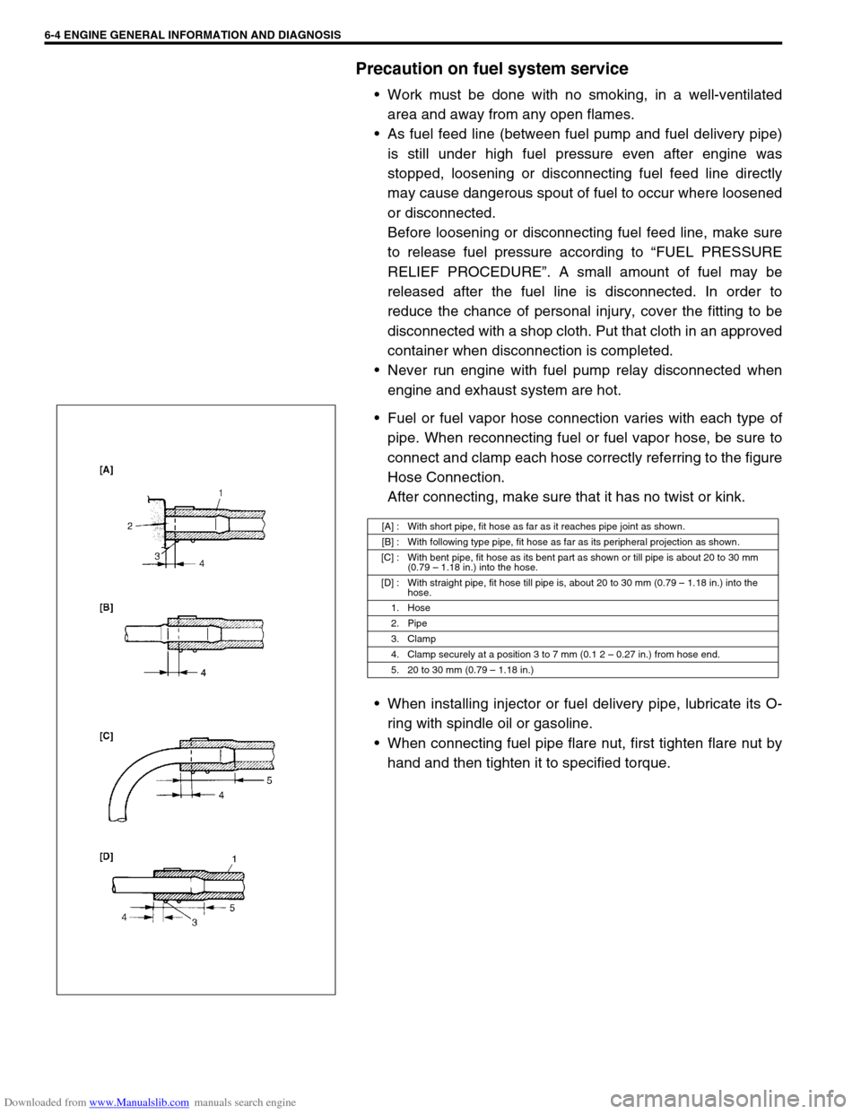
Fuel or fuel vapor hose connection varies with each type of
pipe. When reconnecting fuel or fuel vapor hose, be sure to
connect and clamp each hose correctly referring to the figure
Hose Connection.
After connecting, make sure that it has no twist or kink.
When installing injector or fuel delivery pipe, lubricate its O-
ring with spindle oil or gasoline.
When connecting fuel pipe flare nut, first tighten flare nut by
hand and then tighten it to specified torque.
[A] : With short pipe, fit hose as far as it reaches pipe joint as shown.
[B] : With following type pipe, fit hose as far as its peripheral projection as shown.
[C] : With bent pipe, fit hose as its bent part as shown or till pipe is about 20 to 30 mm
(0.79 – 1.18 in.) into the hose.
[D] : With straight pipe, fit hose till pipe is, about 20 to 30 mm (0.79 – 1.18 in.) into the
hose.
1. Hose
2. Pipe
3. Clamp
4. Clamp securely at a position 3 to 7 mm (0.1 2 – 0.27 in.) from hose end.
5. 20 to 30 mm (0.79 – 1.18 in.)
Page 372 of 687

Downloaded from www.Manualslib.com manuals search engine ENGINE GENERAL INFORMATION AND DIAGNOSIS 6-15
4) After completing the check, turn the ignition switch OFF posi-
tion and disconnect service wire from monitor coupler.
Diagnostic trouble code (DTC) clearance
[Using SUZUKI Scan Tool]
1) Connect SUZUKI scan tool to data link connector in the
same manner as when making this connection for DTC
check.
2) Turn ignition switch ON.
3) Erase DTC and pending DTC according to instructions dis-
played on scan tool. Refer to scan tool operator’s manual for
further details.
4) After completing the clearance, turn ignition switch off and
disconnect scan tool from data link connector.
[Without Using SUZUKI Scan Tool]
1) Turn the ignition switch OFF position.
2) Disconnect battery negative cable for specified time below to
erase diagnostic trouble code stored in ECM memory and
reconnect it.
Time required to erase DTC NOTE:
If abnormality or malfunction lies in two or more areas,
malfunction indicator lamp indicates applicable codes
three times each.
And flashing of these codes is repeated as long as
diagnosis terminal is grounded and ignition switch is
held at ON position.
Take a note of diagnostic trouble code indicated first.
NOTE:
DTC and freeze frame data stored in ECM memory are
also cleared in following cases. Be careful not to clear
them before keeping their record.
When power to ECM is cut off (by disconnecting bat-
tery cable, removing fuse or disconnecting ECM con-
nectors)
When the same malfunction (DTC) is not detected
again during 40 engine warm-up cycles.
Ambient temperature Time to cut power to ECM
Over 0 °C (32 °F) 30 sec. or longer
Under 0 °C (32 °F)Not specifiable.
Select a place with higher than
0 °C (32 °F) temperature.
Page 383 of 687

Downloaded from www.Manualslib.com manuals search engine 6-26 ENGINE GENERAL INFORMATION AND DIAGNOSIS
Excessive engine oil
consumptionSticky piston ring Pistons, piston rings, connecting rods
and cylinders in Section 6A1.
Worn piston and cylinder Pistons, piston rings, connecting rods
and cylinders in Section 6A1.
Worn piston ring groove and ring Pistons, piston rings, connecting rods
and cylinders in Section 6A1.
Improper location of piston ring gap Pistons, piston rings, connecting rods
and cylinders in Section 6A1.
Worn or damaged valve stem seal Valves and cylinder head in Section
6A1.
Worn valve stem Valves and cylinder head in Section
6A1.
Low oil pressure
Improper oil viscosity ITEM1-3 Engine oil and oil filter
change in Section 0B.
Malfunctioning oil pressure switch Oil pressure switch in Section 8.
Clogged oil strainer Oil pan and oil pump strainer in Sec-
tion 6A1.
Functional deterioration of oil pump Oil pump in Section 6A1.
Worn oil pump relief valve Oil pump in Section 6A1.
Excessive clearance in various sliding
partsRefer to Section 6A1.
Engine noise
See NOTE below.Improper valve lash Valve lash in Section 6A1.
Worn valve stem and guide Valves and cylinder head in Section
6A1.
Weak or broken valve spring Valve springs in Section 6A1.
Warped or bent valve Valves and cylinder head in Section
6A1.
Loose camshaft housing bolts Camshaft in Section 6A1.
Worn piston, ring and cylinder bore Pistons and cylinders in Section 6A1.
Worn crankpin bearing Crankpin and connecting rod bearing
in Section 6A1.
Worn crankpin Crankpin and connecting rod bearing
in Section 6A1.
Loose connecting rod nuts Connecting rod in Section 6A1.
Low oil pressure Previously outlined.
Worn crankshaft journal bearing Main bearings, Crankshaft and cylin-
der block in Section 6A1.
Worn crankshaft journal Main bearings, Crankshaft and cylin-
der block in Section 6A1.
Loose lower crankcase (bearing cap) bolts Main bearings, Crankshaft and cylin-
der block in Section 6A1.
Excessive crankshaft thrust play Main bearings, Crankshaft and cylin-
der block in Section 6A1. Condition Possible Cause Reference Item
NOTE:
Before checking the mechanical noise, make sure that :
Ignition timing is properly adjusted.
Specified spark plug is used.
Specified fuel is used.
Page 480 of 687

Downloaded from www.Manualslib.com manuals search engine ENGINE GENERAL INFORMATION AND DIAGNOSIS 6-123
Special Tool
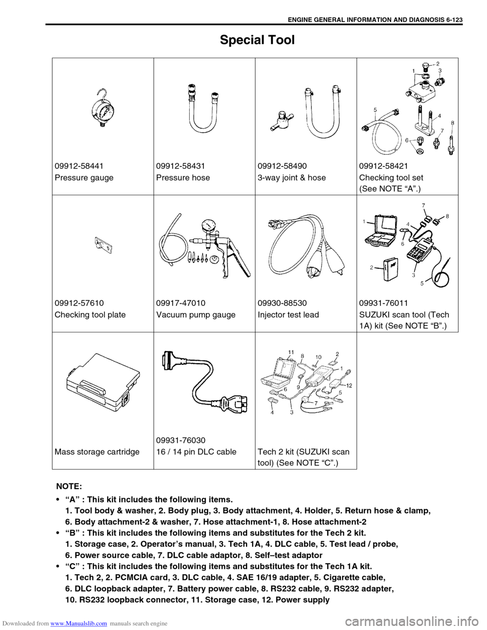
09912-58441 09912-58431 09912-58490 09912-58421
Pressure gauge Pressure hose 3-way joint & hose Checking tool set
(See NOTE “A”.)
09912-57610 09917-47010 09930-88530 09931-76011
Checking tool plate Vacuum pump gauge Injector test lead SUZUKI scan tool (Tech
1A) kit (See NOTE “B”.)
09931-76030
Mass storage cartridge 16 / 14 pin DLC cable Tech 2 kit (SUZUKI scan
tool) (See NOTE “C”.)
NOTE:
“A” : This kit includes the following items.
1. Tool body & washer, 2. Body plug, 3. Body attachment, 4. Holder, 5. Return hose & clamp,
6. Body attachment-2 & washer, 7. Hose attachment-1, 8. Hose attachment-2
“B” : This kit includes the following items and substitutes for the Tech 2 kit.
1. Storage case, 2. Operator’s manual, 3. Tech 1A, 4. DLC cable, 5. Test lead / probe,
6. Power source cable, 7. DLC cable adaptor, 8. Self–test adaptor
“C” : This kit includes the following items and substitutes for the Tech 1A kit.
1. Tech 2, 2. PCMCIA card, 3. DLC cable, 4. SAE 16/19 adapter, 5. Cigarette cable,
6. DLC loopback adapter, 7. Battery power cable, 8. RS232 cable, 9. RS232 adapter,
10. RS232 loopback connector, 11. Storage case, 12. Power supply
Page 535 of 687

Downloaded from www.Manualslib.com manuals search engine 6A1-54 ENGINE MECHANICAL (M13 ENGINE)
Valves
Remove all carbon from valves.
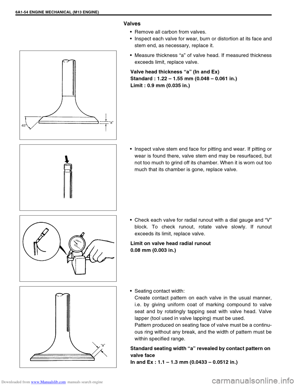
Inspect each valve for wear, burn or distortion at its face and
stem end, as necessary, replace it.
Measure thickness “a” of valve head. If measured thickness
exceeds limit, replace valve.
Valve head thickness “a” (In and Ex)
Standard : 1.22 – 1.55 mm (0.048 – 0.061 in.)
Limit : 0.9 mm (0.035 in.)
Inspect valve stem end face for pitting and wear. If pitting or
wear is found there, valve stem end may be resurfaced, but
not too much to grind off its chamber. When it is worn out too
much that its chamber is gone, replace valve.
Check each valve for radial runout with a dial gauge and “V”
block. To check runout, rotate valve slowly. If runout
exceeds its limit, replace valve.
Limit on valve head radial runout
0.08 mm (0.003 in.)
Seating contact width:
Create contact pattern on each valve in the usual manner,
i.e. by giving uniform coat of marking compound to valve
seat and by rotatingly tapping seat with valve head. Valve
lapper (tool used in valve lapping) must be used.
Pattern produced on seating face of valve must be a continu-
ous ring without any break, and the width of pattern must be
within specified range.
Standard seating width “a” revealed by contact pattern on
valve face
In and Ex : 1.1 – 1.3 mm (0.0433 – 0.0512 in.)
Page 536 of 687

Downloaded from www.Manualslib.com manuals search engine ENGINE MECHANICAL (M13 ENGINE) 6A1-55
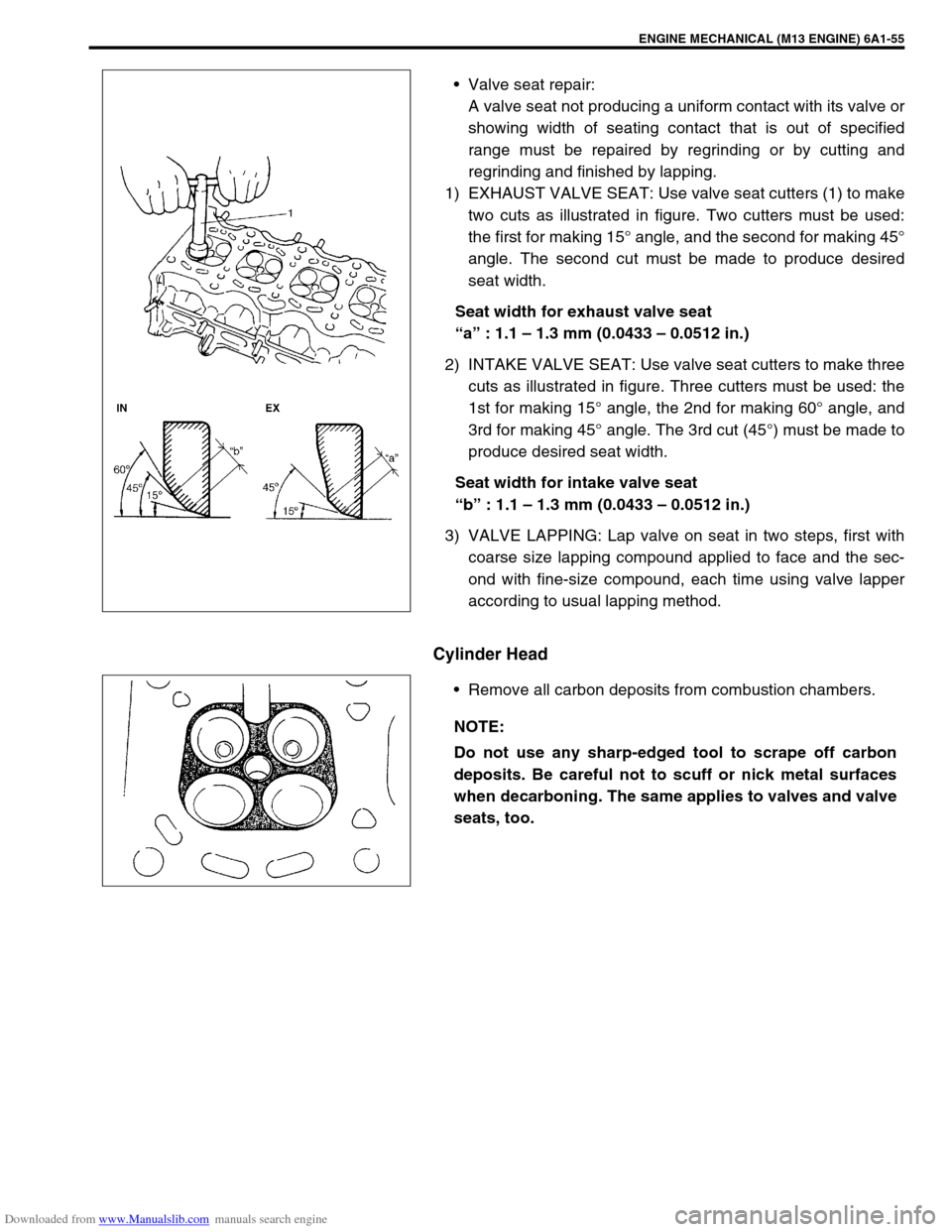
Valve seat repair:
A valve seat not producing a uniform contact with its valve or
showing width of seating contact that is out of specified
range must be repaired by regrinding or by cutting and
regrinding and finished by lapping.
1) EXHAUST VALVE SEAT: Use valve seat cutters (1) to make
two cuts as illustrated in figure. Two cutters must be used:
the first for making 15° angle, and the second for making 45°
angle. The second cut must be made to produce desired
seat width.
Seat width for exhaust valve seat
“a” : 1.1 – 1.3 mm (0.0433 – 0.0512 in.)
2) INTAKE VALVE SEAT: Use valve seat cutters to make three
cuts as illustrated in figure. Three cutters must be used: the
1st for making 15° angle, the 2nd for making 60° angle, and
3rd for making 45° angle. The 3rd cut (45°) must be made to
produce desired seat width.
Seat width for intake valve seat
“b” : 1.1 – 1.3 mm (0.0433 – 0.0512 in.)
3) VALVE LAPPING: Lap valve on seat in two steps, first with
coarse size lapping compound applied to face and the sec-
ond with fine-size compound, each time using valve lapper
according to usual lapping method.
Cylinder Head
Remove all carbon deposits from combustion chambers.
NOTE:
Do not use any sharp-edged tool to scrape off carbon
deposits. Be careful not to scuff or nick metal surfaces
when decarboning. The same applies to valves and valve
seats, too.