Page 120 of 687

Downloaded from www.Manualslib.com manuals search engine FRONT WHEEL ALIGNMENT 3A-3
Diagnosis
Diagnosis Table
For the details, refer to “Diagnosis Table” in Section 3.
Preliminary Checks Prior To Adjusting Front Wheel Alignment
Steering and vibration complaints are not always the result of improper alignment. An additional item to be
checked is the possibility of tire lead due to worn or improperly manufactured tires. “Lead” is the deviation of the
vehicle from a straight path on a level road without hand pressure on the steering wheel. Section 3 of this man-
ual contains a procedure for determining the presence of a tire lead problem. Before making any adjustment
affecting toe setting, the following checks and inspections should be made to ensure correctness of alignment
readings and alignment adjustments:
1) Check all tires for proper inflation pressures and approximately the same tread wear.
2) Check for loose of king pin bearings. Check tie rod ends; if excessive looseness is noted, it must be cor-
rected before adjusting.
3) Check for run-out of wheels and tires.
4) Check vehicle trim heights; if out of limits and a correction is to be made, it must be made before adjusting
toe.
5) Check for loose of suspension arms.
6) Check for loose or missing stabilizer bar attachments.
7) Consideration must be given to excess loads, such as tool boxes. If this excess load is normally carried in
vehicle, it should remain in vehicle during alignment checks.
8) Consider condition of equipment being used to check alignment and follow manufacturer's instructions.
9) Regardless of equipment used to check alignment, vehicle must be on a level surface both fore and aft and
transversely.
Toe Adjustment
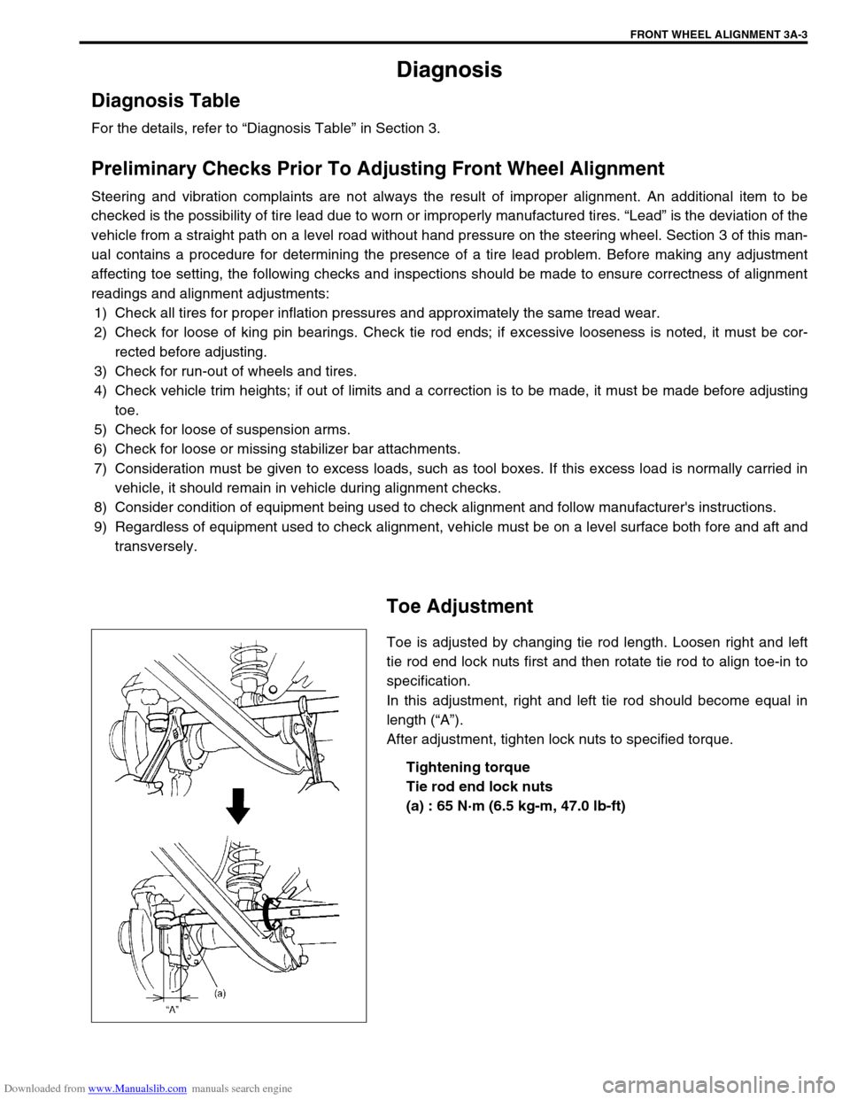
Toe is adjusted by changing tie rod length. Loosen right and left
tie rod end lock nuts first and then rotate tie rod to align toe-in to
specification.
In this adjustment, right and left tie rod should become equal in
length (“A”).
After adjustment, tighten lock nuts to specified torque.
Tightening torque
Tie rod end lock nuts
(a) : 65 N·m (6.5 kg-m, 47.0 lb-ft)
Page 124 of 687
Downloaded from www.Manualslib.com manuals search engine STEERING GEAR BOX (MANUAL TYPE) AND LINKAGE 3B-3
Diagnosis
Diagnosis Table
Refer to “Diagnosis Table” in Section 3.
Steering Wheel Play Check
Check steering wheel for play and rattle, holding vehicle in
straight forward condition on ground.
Steering wheel play
“a” : 10 – 30 mm (0.4 – 1.2 in.)
If play is not within specification, inspect for the following. If found
defective, replace.
Wear of tie rod end ball stud.
Wear of king pin bearing
Wear of steering shaft joint.
Loosely install or joined parts.
Wear of steering rack / sector gear.
Tie Rod And Drag Rod Check
Inspect deformation or damage. Replace any defective part.
INSPECTION
1) Inspect for play in tie rod end ball joint (1). If found defective,
replace.
2) Inspect boot (2) for tear. If even a small tear is noted, replace
with new one.
Page 131 of 687
Downloaded from www.Manualslib.com manuals search engine 3B-10 STEERING GEAR BOX (MANUAL TYPE) AND LINKAGE
Tightening Torque Specifications
Required Service Material
Special Tools
Fastening partTightening torque
Nm kg-m lb-ft
Steering gear box oil plug 4 0.4 3.0
Steering gear box adjusting bolt lock nut 30 3.0 22.0
Pitman arm mounting nut 135 13.5 98.0
Steering shaft joint bolt 25 2.5 18.0
Steering gear box nuts and bolt 80 8.0 58.0
Tie rod end nut and drag rod end nut
(knuckle side)43 4.3 31.5
Wheel nut 95 9.5 69.0
Tie rod end lock nut 65 6.5 47.0
Drag rod end nut (pitman arm side) 50 5.0 36.5
MaterialRecommended SUZUKI product
(Part Number)Use
Sealant SUZUKI BOND NO. 1215
(99000-31110)Thread of oil breathing plug
09913-65210 09944-18211
Tie-rod end remover Pinion torque checking socket
Page 134 of 687

Downloaded from www.Manualslib.com manuals search engine POWER STEERING (P/S) SYSTEM (If equipped) 3B1-3
Diagnosis
Diagnosis Table
Condition Possible Cause Correction
Steering wheel feels
heavy
(at low speed)Fluid deteriorated, low viscosity, different type of
fluid mixedChange fluid.
Pipes or hoses deformed, air entering through
jointCorrect or replace.
Insufficient air bleeding from piping Bleed air.
Belt worn, lacking in tension Adjust belt tension or replace belt
as necessary.
Tire inflation pressure too low Inflate tire.
Wheel alignment out of adjustment Adjust front wheel alignment.
Steering wheel installed improperly (twisted) Install steering wheel correctly.
Hydraulic pressure failing to rise (See NOTE
“A”.)Replace P/S pump.
Slow hydraulic pressure rise (See NOTE “A”.)
Steering wheel feels
heavy momentarily
when turning it to the
left or right.Air drawn in due to insufficient amount of fluid Add fluid and bleed air.
Slipping belt Adjust belt tension or replace belt
as necessary.
No idle-up (See NOTE
“B”.)Defective pressure switch Replace pressure switch
(terminal set).
NOTE:
“A” : Be sure to warm up engine fully before performing this check. Pump vanes are sometimes
hard to come out where temperature is low.
“B” : Acceptable if idling speed does not drop.
Condition Possible Cause Correction
Steering wheel returns
slowly from turns.
(See NOTE “C”.)Dust or foreign object mixed in fluid Change fluid.
Deformed pipes or hoses Correct or replace.
Steering column installed improperly Install correctly.
Wheel alignment maladjusted Adjust.
Linkage or joints not operating smoothly Correct.
Vehicle pulls to one
side during straight
driving.Low or uneven tire inflation pressure Inflate tire (s) as necessary.
Wheel alignment maladjusted Adjust.
Defective spool valve Replace gear box assembly.
Steering wheel play is
large and vehicle wan-
ders.Loose steering shaft nut Retighten.
Loose linkage or joint Retighten.
Loose gear box fixing bolt Retighten.
Front wheel bearing worn Replace.
Fluid leakage
Loose joints of hydraulic pressure pipes and
hosesRetighten.
Deformed or damaged pipes or hoses Correct or replace.
Gear box Replace gear box assembly.
Page 174 of 687

Downloaded from www.Manualslib.com manuals search engine FRONT SUSPENSION 3D-1
6F1
6F2
6G
1A
6K
7A
7A1
3D
7F
8A
8A
8B
8C
8D
8E
9
10
10A
10B
SECTION 3D
FRONT SUSPENSION
CONTENTS
General Description ....................................... 3D-2
4WD Control System .................................... 3D-2
Diagnosis ........................................................ 3D-8
Diagnosis Table ........................................... 3D-8
4WD Controller and ITS Circuit Check ....... 3D-10
4WD Control System Check ...................... 3D-11
Stabilizer bar / bushing check ................ 3D-13
Shock Absorber and/or Coil Spring
Check ......................................................... 3D-14
Leading Arm / Lateral Rod / Steering
Knuckle Check ........................................... 3D-14
Leading Arm Bushing / Lateral Rod
Bushing Check ........................................... 3D-15
Kingpin / Kingpin Bearing Check ................ 3D-15
Barfield Joint Check ................................... 3D-15
Steering Knuckle Seal Check ..................... 3D-15
Wheel Disc, Nut and Bearing Check .......... 3D-16On-Vehicle Service ...................................... 3D-17
Stabilizer Bar / Bushings ............................ 3D-17
Front Shock Absorber ................................ 3D-19
Coil Spring ................................................. 3D-19
Bump Stopper and Spring Upper Seat ...... 3D-21
Wheel Hub / Bearing / Oil Seal .................. 3D-21
Steering Knuckle / Wheel Spindle.............. 3D-28
Front Axle Shaft / Oil Seal / Kingpin
Bearing Outer Race ................................... 3D-32
Steering Knuckle Seal................................ 3D-34
Lateral Rod ................................................ 3D-35
Leading Arm / Bushing............................... 3D-36
Front Axle Housing .................................... 3D-38
Tightening Torque Specifications .............. 3D-44
Required Service Material ........................... 3D-44
Special Tool .................................................. 3D-45
WARNING:
When hoisting vehicle, be sure to select the lifting point suitable for the service work referring to Sec-
tion 0A.
NOTE:
All front suspension fasteners are an important attaching part in that it could affect the performance
of vital parts and systems, and/or could result in major repair expense. They must be replaced with
one of the same part number or with an equivalent part if replacement becomes necessary. Do not
use a replacement part of lesser quality or substitute design. Torque values must be used as speci-
fied during reassembly to assure proper retention of this part.
Never attempt to heat, quench or straighten any front suspension part. Replace it with a new part or
damage to the part may result.
Page 175 of 687
Downloaded from www.Manualslib.com manuals search engine 3D-2 FRONT SUSPENSION
General Description
4WD Control System
The 4WD control system consists of a 4WD switch, a vacuum switch, a vacuum tank, two vacuum switching
valves (VSV1 and VSV2) and air locking hub assemblies.
The 4WD controller controls locking or unlocking of the air locking hub according to operation of the transfer shift
control lever.
Vacuum generated in the intake manifold passes through the check valve and stored in the vacuum tank.
According to signals from the 4WD switch, the 4WD controller activates VSV1 (for unlocking) or VSV2 (for lock-
ing) to apply vacuum from the vacuum tank so that the front axle and the wheel hub are disengaged or engaged.
1. Front axle housing 3. Steering knuckle 5. Wheel spindle 7. Wheel bearing
2. Shock absorber 4. Kingpin 6. Wheel hub 8. Front axle shaft (4WD)
Page 176 of 687
Downloaded from www.Manualslib.com manuals search engine FRONT SUSPENSION 3D-3
1. Air locking hub assembly 4. VSV2 7. 4WD controller 10. 4WD indicator light 13. ABS controller
2. VSV1 5. Vacuum accumulation tank 8. Intake manifold 11. 4WD switch 14. Transfer
3. Check valve 6. Vacuum switch 9. Wheel spindle 12. Combination meter
Page 184 of 687

Downloaded from www.Manualslib.com manuals search engine FRONT SUSPENSION 3D-11
4WD Control System Check
AIR LOCKING HUB
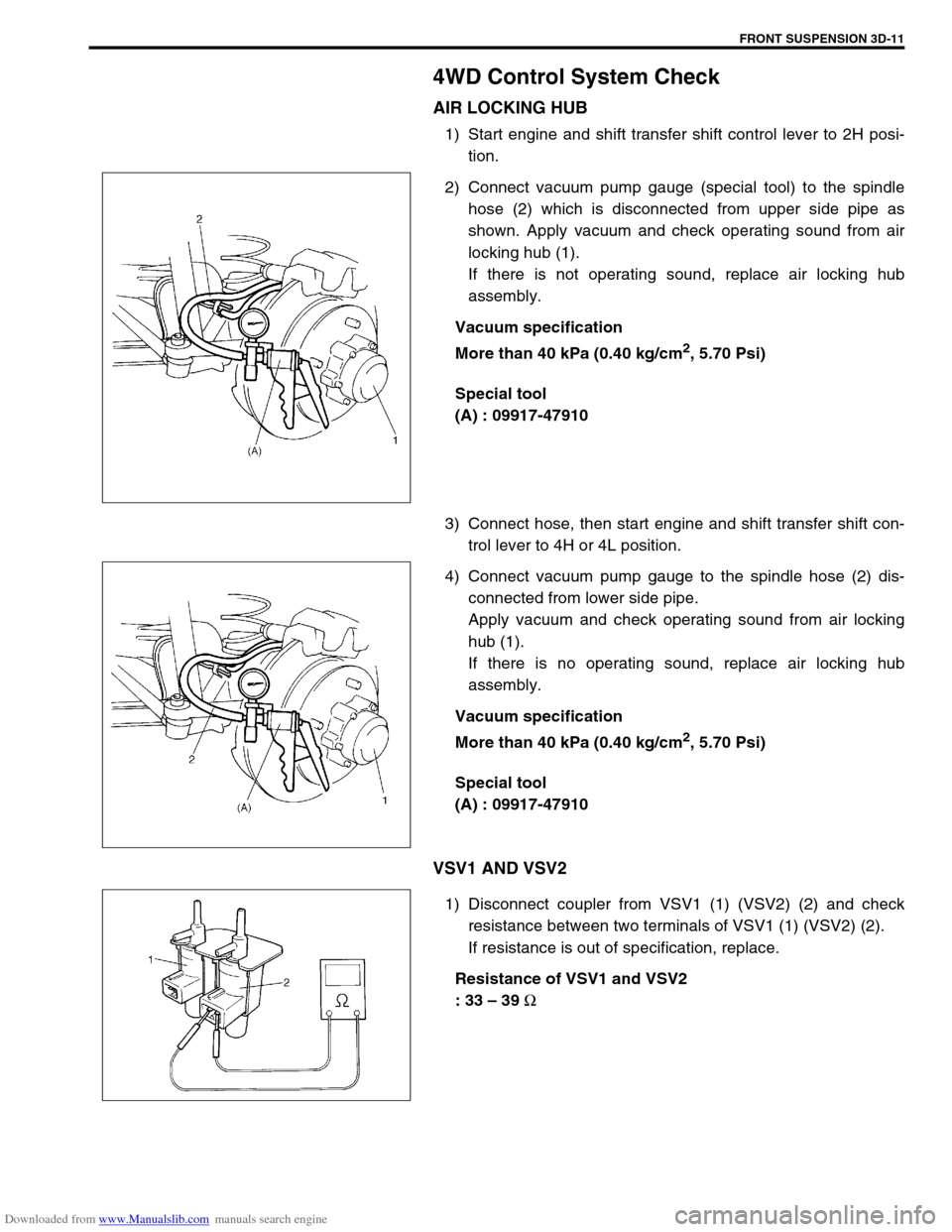
1) Start engine and shift transfer shift control lever to 2H posi-
tion.
2) Connect vacuum pump gauge (special tool) to the spindle
hose (2) which is disconnected from upper side pipe as
shown. Apply vacuum and check operating sound from air
locking hub (1).
If there is not operating sound, replace air locking hub
assembly.
Vacuum specification
More than 40 kPa (0.40 kg/cm
2, 5.70 Psi)
Special tool
(A) : 09917-47910
3) Connect hose, then start engine and shift transfer shift con-
trol lever to 4H or 4L position.
4) Connect vacuum pump gauge to the spindle hose (2) dis-
connected from lower side pipe.
Apply vacuum and check operating sound from air locking
hub (1).
If there is no operating sound, replace air locking hub
assembly.
Vacuum specification
More than 40 kPa (0.40 kg/cm
2, 5.70 Psi)
Special tool
(A) : 09917-47910
VSV1 AND VSV2
1) Disconnect coupler from VSV1 (1) (VSV2) (2) and check
resistance between two terminals of VSV1 (1) (VSV2) (2).
If resistance is out of specification, replace.
Resistance of VSV1 and VSV2
: 33 – 39
Ω