2005 SUZUKI JIMNY ATE
[x] Cancel search: ATEPage 597 of 687

Downloaded from www.Manualslib.com manuals search engine 6C-2 ENGINE FUEL
General Description
Fuel System
The main components of the fuel system are fuel tank, fuel pump assembly with fuel filter and fuel level gauge
and fuel cut valve, fuel feed line, fuel return line and fuel vapor line.
For the details of fuel flow and fuel vapor flow, refer to “Fuel Delivery System” and “Emission Control System” in
Section 6E.
Fuel Tank
The fuel tank is located under the rear section of the vehicle. The
fuel pump assembly is installed in fuel tank. Whenever servicing
the fuel pump assembly, the fuel tank must be removed from the
vehicle.
1. Fuel tank 4. Fuel filler cap 7. Fuel vapor line 10. Fuel filler hose clamp
2. Fuel pump assembly 5. Fuel feed line 8. Fuel filler neck Tightening torque
3. Breather hose 6. Fuel return line 9. Fuel tank mounting bolt
Page 598 of 687

Downloaded from www.Manualslib.com manuals search engine ENGINE FUEL 6C-3
Fuel Pump Assembly
The fuel pump assembly (1) consists of fuel pump (6), fuel filter
(2), fuel level gauge (5) and fuel cut valve (4).
FUEL PUMP
For structure and operation of the fuel pump, refer to “Fuel Deliv-
ery System” in Section 6E.
FUEL CUT VALVE
The fuel cut valve consists of a float and a spring. It allows only
the fuel vapor to flow into the canister and prevents the fuel from
flowing into the canister.
Fuel Filler Cap
The fuel tank filler neck has a vacuum cap.
A ratchet tightening device on the threaded fuel filler cap reduces
the chances of incorrect installation, which would prevent sealing
fuel vapors.
After the gasket (2) on fuel filler cap and the filler neck flange con-
tact, the ratchet produces a loud clicking noise, indicating the seal
has been set.
This cap has a vacuum relief valve (1) inside.
The vacuum relief valve opens to relieve the vacuum created in
the fuel tank.
3. Suction filter
Page 600 of 687

Downloaded from www.Manualslib.com manuals search engine ENGINE FUEL 6C-5
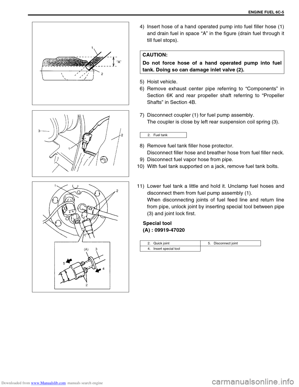
4) Insert hose of a hand operated pump into fuel filler hose (1)
and drain fuel in space “A” in the figure (drain fuel through it
till fuel stops).
5) Hoist vehicle.
6) Remove exhaust center pipe referring to “Components” in
Section 6K and rear propeller shaft referring to “Propeller
Shafts” in Section 4B.
7) Disconnect coupler (1) for fuel pump assembly.
The coupler is close by left rear suspension coil spring (3).
8) Remove fuel tank filler hose protector.
Disconnect filler hose and breather hose from fuel filler neck.
9) Disconnect fuel vapor hose from pipe.
10) With fuel tank supported on a jack, remove fuel tank bolts.
11) Lower fuel tank a little and hold it. Unclamp fuel hoses and
disconnect them from fuel pump assembly (1).
When disconnecting joints of fuel feed line and return line
from pipe, unlock joint by inserting special tool between pipe
(3) and joint lock first.
Special tool
(A) : 09919-47020 CAUTION:
Do not force hose of a hand operated pump into fuel
tank. Doing so can damage inlet valve (2).
2. Fuel tank
2. Quick joint 5. Disconnect joint
4. Insert special tool
Page 601 of 687

Downloaded from www.Manualslib.com manuals search engine 6C-6 ENGINE FUEL
12) Remove fuel tank (1) from vehicle. Remove fuel tank protec-
tor (3) and inlet valve (2) as necessary.
FUEL TANK PURGING PROCEDURE
The following procedure is used for purging the fuel tank.
1) After removing fuel tank, remove all hoses and fuel pump
assembly from fuel tank.
2) Drain all remaining fuel from tank.
3) Move tank to flushing area.
4) Fill tank with warm water or tap water, and agitate vigorously
and drain. Repeat this washing until inside of tank is clean.
Replace tank if its inside is rusty.
5) Completely flush out remaining water after washing.
CAUTION:
This purging procedure will not remove all fuel vapor. Do
not attempt any repair on tank where heat or flame is
required, as an explosion resulting in personal injury
could occur.
Page 604 of 687

Downloaded from www.Manualslib.com manuals search engine ENGINE FUEL 6C-9
INSTALLATION
1) Clean mating surfaces of fuel pump assembly and fuel tank.
2) Install new gasket (2) and plate (3) to fuel pump assembly
(1) then install fuel pump assembly to fuel tank.
Tightening torque
Fuel pump assembly bolts (a) : 10 N·m (1.0 kg-m, 7.5 lb-ft)
3) Connect wire harness coupler (2) and fuel vapor hose (3) to
fuel pump assembly (1).
4) Install fuel tank to vehicle. Refer to “Fuel Tank” in this sec-
tion. CAUTION:
While removing fuel level gauge, do not contact resis-
tor plate (2) or deform arm (3). It may cause fuel level
gauge to fail.
When removing grommet from fuel tube or bracket sub
assembly, be very careful not to cause damage to
grommet installed section (sealed section in bore).
Should it be damaged, replace it with new one, or fuel
will leak from that part.
NOTE:
When removing fuel level gauge, press snap-fit part (1)
and slide it in the arrow direction as shown in figure.
When installing fuel level gauge to housing, fit protru-
sion (4) of fuel level gauge in groove (5) in housing and
slide it up till lug (6) fits in window (7) securely. Refer to
figure shown.
[A] : Removal
[B] : Installation
Page 606 of 687

Downloaded from www.Manualslib.com manuals search engine ENGINE AND EMISSION CONTROL SYSTEM 6E-1
6F1
6F2
6G
7C1
7D
7E
7A
7A1
7B1
7C1
7D
7E
7F
8A
8B
8C
8D
6H
6E
10
10A
10B
SECTION 6E
ENGINE AND EMISSION CONTROL SYSTEM
CONTENTS
General Description ....................................... 6E-3
Air Intake System ......................................... 6E-5
Fuel Delivery System ................................... 6E-6
Fuel pump ................................................ 6E-6
Electronic Control System ............................ 6E-7
Engine & emission control input / output
table.......................................................... 6E-8
On-Vehicle Service....................................... 6E-15
Accelerator cable adjustment ................. 6E-15
Idle speed / idle air control (IAC) duty
inspection ............................................... 6E-15
Idle mixture inspection / adjustment
(vehicle without heated oxygen
sensor) ................................................... 6E-17
Air Intake System ....................................... 6E-18
Throttle body .......................................... 6E-18
Idle air control valve (IAC valve)............. 6E-21
Fuel Delivery System ................................. 6E-22
Fuel pressure inspection ........................ 6E-22
Fuel pump .............................................. 6E-23
Fuel pressure regulator .......................... 6E-24
Fuel injector ............................................ 6E-25
Electronic Control System .......................... 6E-29Engine control module (ECM) ................ 6E-29
Manifold absolute pressure sensor (MAP
sensor) ................................................... 6E-29
Throttle position sensor (TP sensor) ...... 6E-30
Intake air temperature sensor
(IAT sensor) ........................................... 6E-31
Engine coolant temperature sensor
(ECT sensor) .......................................... 6E-32
Heated oxygen sensor
(Sensor-1 and sensor-2) ........................ 6E-33
Camshaft position sensor....................... 6E-34
Crankshaft position sensor..................... 6E-35
Vehicle speed sensor (VSS) .................. 6E-36
Fuel level sensor (GAUGE).................... 6E-36
Knock sensor ......................................... 6E-36
Main relay, fuel pump relay and A/C
condenser fan control relay .................... 6E-36
Fuel cut operation .................................. 6E-37
A/C condenser fan control system ......... 6E-37
A/C condenser fan ................................. 6E-37
Output signals of throttle valve opening
and engine coolant temp.
(Vehicle with A/T only) ........................... 6E-38
Emission Control System ........................... 6E-38 WARNING:
For vehicles equipped with Supplemental Restraint (Air Bag) System:
Service on and around the air bag system components or wiring must be performed only by an
authorized SUZUKI dealer. Refer to “Air Bag System Components and Wiring Location View” under
“General Description” in air bag system section in order to confirm whether you are performing ser-
vice on or near the air bag system components or wiring. Please observe all WARNINGS and “Ser-
vice Precautions” under “On-Vehicle Service” in air bag system section before performing service
on or around the air bag system components or wiring. Failure to follow WARNINGS could result in
unintentional activation of the system or could render the system inoperative. Either of these two
conditions may result in severe injury.
Technical service work must be started at least 90 seconds after the ignition switch is turned to the
“LOCK” position and the negative cable is disconnected from the battery. Otherwise, the system
may be activated by reserve energy in the Sensing and Diagnostic Module (SDM).
NOTE:
Whether following systems (parts) are used in the particular vehicle or not depends on specifications.
Be sure to bear this in mind when performing service work.
EGR valve
Heated oxygen sensor (s) or CO adjusting resistor
Three way catalytic converter (TWC) and warm up three-way catalytic converter (WU-TWC)
Page 610 of 687

Downloaded from www.Manualslib.com manuals search engine ENGINE AND EMISSION CONTROL SYSTEM 6E-5
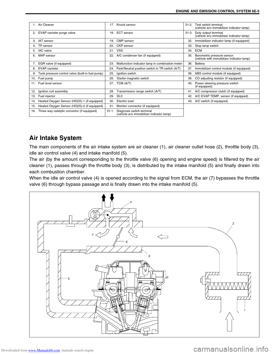
Air Intake System
The main components of the air intake system are air cleaner (1), air cleaner outlet hose (2), throttle body (3),
idle air control valve (4) and intake manifold (5).
The air (by the amount corresponding to the throttle valve (6) opening and engine speed) is filtered by the air
cleaner (1), passes through the throttle body (3), is distributed by the intake manifold (5) and finally drawn into
each combustion chamber.
When the idle air control valve (4) is opened according to the signal from ECM, the air (7) bypasses the throttle
valve (6) through bypass passage and is finally drawn into the intake manifold (5).
1. Air Cleaner 17. Knock sensor 31-2. Test switch terminal
(vehicle w/o immobilizer indicator lamp)
2. EVAP canister purge valve 18. ECT sensor 31-3. Duty output terminal
(vehicle w/o immobilizer indicator lamp)
3. IAT sensor 19. CMP sensor 32. Immobilizer indicator lamp (if equipped)
4. TP sensor 20. CKP sensor 33. Stop lamp switch
5. IAC valve 21. VSS 34. ECM
6. MAP sensor 22. A/C condenser fan (if equipped) 35. Barometric pressure sensor
(vehicle with immobilizer indicator lamp)
7. EGR valve (if equipped) 23. Malfunction indicator lamp in combination meter 36. Battery
8. EVAP canister 24. Park/Neutral position switch in TR switch (A/T) 37. Immobilizer control module (if equipped)
9. Tank pressure control valve (built-in fuel pump) 25. Ignition switch 38. ABS control module (if equipped)
10. Fuel pump 26. Starter magnetic switch 39. CO adjusting resistor (if equipped)
11. Fuel level sensor 27. TCM (A/T) 40. Power steering pressure switch
(if equipped)
12. Ignition coil assembly 28. Transmission range switch (A/T) 41. A/C compressor clutch (if equipped)
13. Fuel injector 29. DLC 42. A/C EVAP TEMP. sensor (if equipped)
14. Heated Oxygen Sensor (HO2S)-1 (if equipped) 30. Electric load 43. A/C switch (if equipped)
15. Heated Oxygen Sensor (HO2S)-2 (if equipped) 31. Monitor connector (if equipped)
16. Three way catalytic convertor (if equipped) 31-1. Diagnosis switch terminal
(vehicle w/o immobilizer indicator lamp)
Page 611 of 687

Downloaded from www.Manualslib.com manuals search engine 6E-6 ENGINE AND EMISSION CONTROL SYSTEM
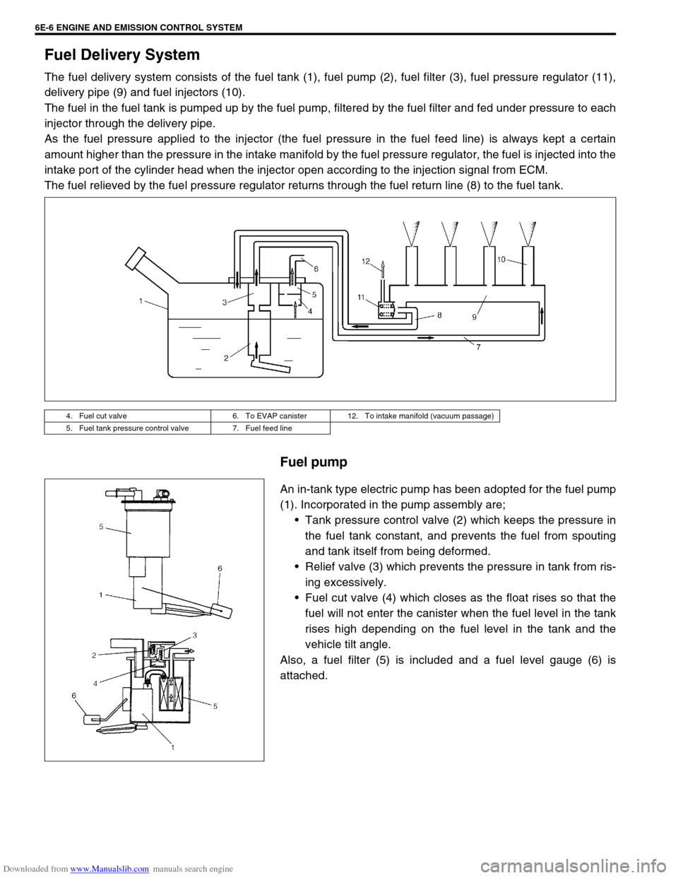
Fuel Delivery System
The fuel delivery system consists of the fuel tank (1), fuel pump (2), fuel filter (3), fuel pressure regulator (11),
delivery pipe (9) and fuel injectors (10).
The fuel in the fuel tank is pumped up by the fuel pump, filtered by the fuel filter and fed under pressure to each
injector through the delivery pipe.
As the fuel pressure applied to the injector (the fuel pressure in the fuel feed line) is always kept a certain
amount higher than the pressure in the intake manifold by the fuel pressure regulator, the fuel is injected into the
intake port of the cylinder head when the injector open according to the injection signal from ECM.
The fuel relieved by the fuel pressure regulator returns through the fuel return line (8) to the fuel tank.
Fuel pump
An in-tank type electric pump has been adopted for the fuel pump
(1). Incorporated in the pump assembly are;
Tank pressure control valve (2) which keeps the pressure in
the fuel tank constant, and prevents the fuel from spouting
and tank itself from being deformed.
Relief valve (3) which prevents the pressure in tank from ris-
ing excessively.
Fuel cut valve (4) which closes as the float rises so that the
fuel will not enter the canister when the fuel level in the tank
rises high depending on the fuel level in the tank and the
vehicle tilt angle.
Also, a fuel filter (5) is included and a fuel level gauge (6) is
attached.
4. Fuel cut valve 6. To EVAP canister 12. To intake manifold (vacuum passage)
5. Fuel tank pressure control valve 7. Fuel feed line