Page 555 of 687

Downloaded from www.Manualslib.com manuals search engine 6A1-74 ENGINE MECHANICAL (M13 ENGINE)
a) For right hand steering vehicle:
With hose connected, detach A/C compressor from its
bracket.
b) For left hand steering vehicle:
i) Recover refrigerant from refrigeration system using recov-
ery and recycling equipment.
ii) Disconnect magnet clutch lead wire.
iii) Remove suction pipe and disconnect discharge pipe from
A/C compressor.
iv) Remove A/C compressor from its bracket.
When servicing above steps, refer to “Compressor” in Section 1B.
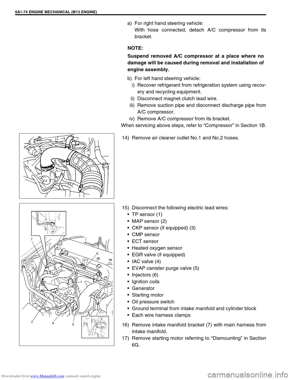
14) Remove air cleaner outlet No.1 and No.2 hoses.
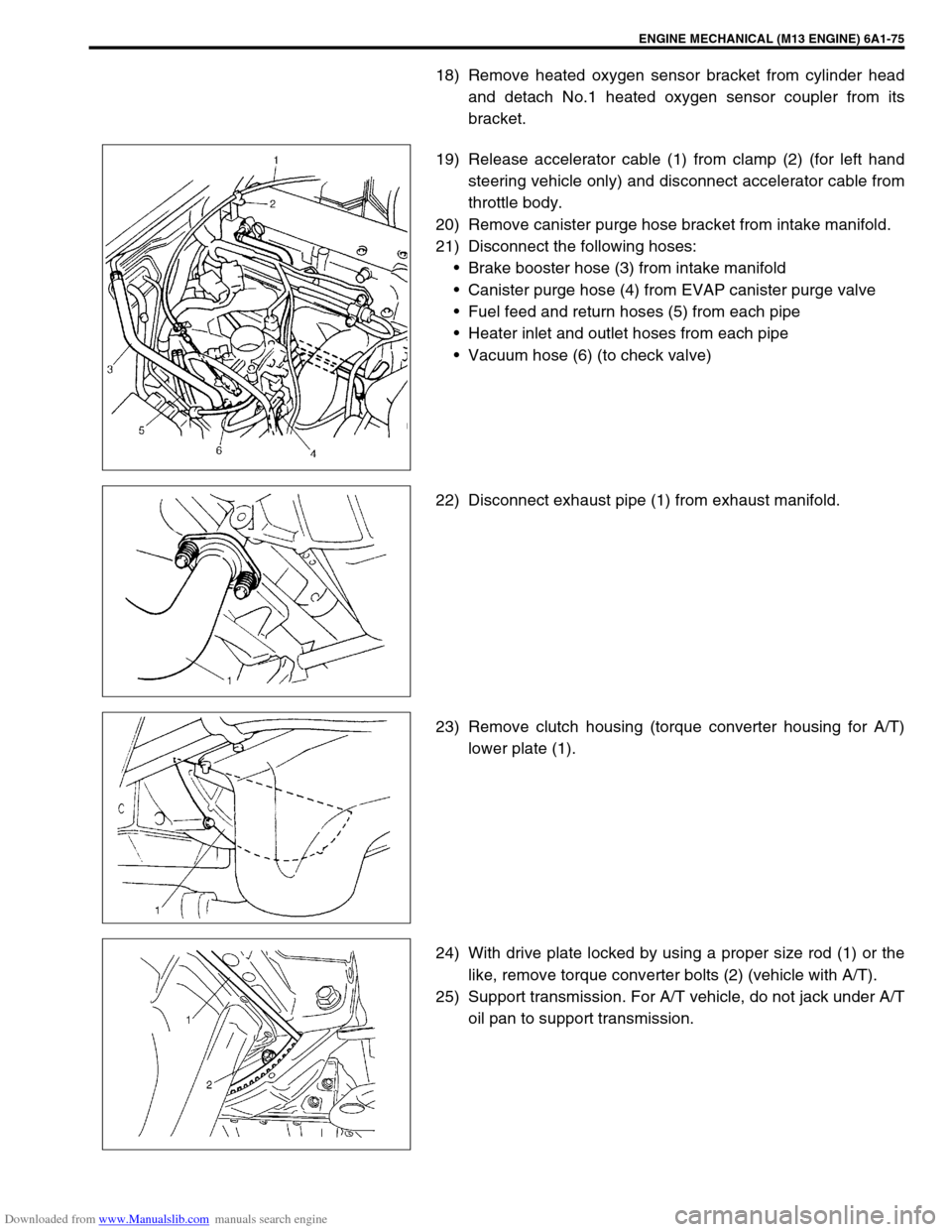
15) Disconnect the following electric lead wires:
TP sensor (1)
MAP sensor (2)
CKP sensor (if equipped) (3)
CMP sensor
ECT sensor
Heated oxygen sensor
EGR valve (if equipped)
IAC valve (4)
EVAP canister purge valve (5)
Injectors (6)
Ignition coils
Generator
Starting motor
Oil pressure switch
Ground terminal from intake manifold and cylinder block
Each wire harness clamps
16) Remove intake manifold bracket (7) with main harness from
intake manifold.
17) Remove starting motor referring to “Dismounting” in Section
6G. NOTE:
Suspend removed A/C compressor at a place where no
damage will be caused during removal and installation of
engine assembly.
Page 556 of 687

Downloaded from www.Manualslib.com manuals search engine ENGINE MECHANICAL (M13 ENGINE) 6A1-75
18) Remove heated oxygen sensor bracket from cylinder head
and detach No.1 heated oxygen sensor coupler from its
bracket.
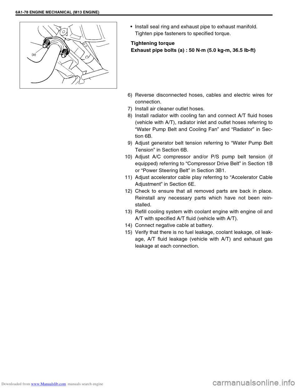
19) Release accelerator cable (1) from clamp (2) (for left hand
steering vehicle only) and disconnect accelerator cable from
throttle body.
20) Remove canister purge hose bracket from intake manifold.
21) Disconnect the following hoses:
Brake booster hose (3) from intake manifold
Canister purge hose (4) from EVAP canister purge valve
Fuel feed and return hoses (5) from each pipe
Heater inlet and outlet hoses from each pipe
Vacuum hose (6) (to check valve)
22) Disconnect exhaust pipe (1) from exhaust manifold.
23) Remove clutch housing (torque converter housing for A/T)
lower plate (1).
24) With drive plate locked by using a proper size rod (1) or the
like, remove torque converter bolts (2) (vehicle with A/T).
25) Support transmission. For A/T vehicle, do not jack under A/T
oil pan to support transmission.
Page 559 of 687

Downloaded from www.Manualslib.com manuals search engine 6A1-78 ENGINE MECHANICAL (M13 ENGINE)
Install seal ring and exhaust pipe to exhaust manifold.
Tighten pipe fasteners to specified torque.
Tightening torque
Exhaust pipe bolts (a) : 50 N·m (5.0 kg-m, 36.5 lb-ft)
6) Reverse disconnected hoses, cables and electric wires for
connection.
7) Install air cleaner outlet hoses.
8) Install radiator with cooling fan and connect A/T fluid hoses
(vehicle with A/T), radiator inlet and outlet hoses referring to
“Water Pump Belt and Cooling Fan” and “Radiator” in Sec-
tion 6B.
9) Adjust generator belt tension referring to “Water Pump Belt
Tension” in Section 6B.
10) Adjust A/C compressor and/or P/S pump belt tension (if
equipped) referring to “Compressor Drive Belt” in Section 1B
or “Power Steering Belt” in Section 3B1.
11) Adjust accelerator cable play referring to “Accelerator Cable
Adjustment” in Section 6E.
12) Check to ensure that all removed parts are back in place.
Reinstall any necessary parts which have not been rein-
stalled.
13) Refill cooling system with coolant engine with engine oil and
A/T with specified A/T fluid (vehicle with A/T).
14) Connect negative cable at battery.
15) Verify that there is no fuel leakage, coolant leakage, oil leak-
age, A/T fluid leakage (vehicle with A/T) and exhaust gas
leakage at each connection.
Page 560 of 687
Downloaded from www.Manualslib.com manuals search engine ENGINE MECHANICAL (M13 ENGINE) 6A1-79
Main Bearings, Crankshaft and Cylinder Block
Tightening torque 4. Venturi plug 12. Input shaft bearing
Do not reuse. 5. Main bearing 13. Flywheel
Apply engine oil to inside / sliding
surface.6. Sensor plate 14. Main bearing cap
“a” : 3 mm (0.12 in.) 7. Crankshaft timing sprocket key 15. Flywheel mounting bolt
: Apply sealant 99000-31110 to thread
part.
“b” : 2 mm (0.08 in.) 8. Crankshaft 16. Rear oil seal housing mounting bolt
1. CKP sensor (if equipped) 9. Thrust bearing 17. Main bearing cap No.2 bolt
2. Knock sensor 10. Rear oil seal housing
: Apply specified amount [A] of seal-
ant 99000-31150 to mating surface. 18. Main bearing cap No.1 bolt
1) Tighten all bolts to 50 N·m (5.0 kg-m)
2) Then, turn all bolts to 60°
3. Cylinder block 11. Rear oil seal
Page 561 of 687
Downloaded from www.Manualslib.com manuals search engine 6A1-80 ENGINE MECHANICAL (M13 ENGINE)
REMOVAL
1) Remove engine assembly from vehicle as previously out-
lined.
2) Remove clutch cover, clutch disc and flywheel (drive plate
for A/T) by using special tool.
Special tool
(A) : 09924-17810
3) Remove the following parts from engine as previously out-
lined.
Oil pan and oil pump strainer
Intake manifold and exhaust manifold
Cylinder head cover
Timing chain cover
Timing chain guide, chain tensioner adjuster, chain ten-
sioner, timing chain and crankshaft timing sprocket
Camshaft, tappet and shim
Cylinder head assembly
Piston and connecting rod
4) Remove rear oil seal housing (1).
5) Loosen bearing cap No.1 and No.2 bolts in such order as
indicated in figure and remove them.
6) Remove crankshaft from cylinder block.
Page 562 of 687

Downloaded from www.Manualslib.com manuals search engine ENGINE MECHANICAL (M13 ENGINE) 6A1-81
INSPECTION
Main bearing cap No.1 bolt
Measure each thread diameter of bearing cap No.1 bolts (1) at
“A” on 60 mm (2.36 in.) from seat side of flange bolt and “B” on 90
mm (3.54 in.) from seat side of flange bolt by using a micrometer
(2).
Calculate difference in diameters (“A” – “B”).
If it exceeds limit, replace with new one.
Bearing cap No.1 bolt diameter measurement points
“a” : 60 mm (2.36 in.)
“b” : 90 mm (3.54 in.)
Bearing cap No.1 bolt diameter difference
Limit (“A” – “B”) : 0.2 mm (0.008 in.)
Crankshaft
Crankshaft runout
Using a dial gauge, measure runout at center journal. Rotate
crankshaft slowly. If runout exceeds its limit, replace crankshaft.
Crankshaft runout
Limit : 0.04 mm (0.0016 in.)
Crankshaft thrust play
Measure this play with crankshaft set in cylinder block in the nor-
mal manner, that is with thrust bearing (1) and journal bearing
caps installed.
Thickness of crankshaft thrust bearing
Standard : 2.500 mm (0.0984 in.)
Oversize (0.125 mm (0.0049 in.)) : 2.563 mm (0.1009 in.)
“A”
“a”
“b”“B”
1
1
2
Page 564 of 687

Downloaded from www.Manualslib.com manuals search engine ENGINE MECHANICAL (M13 ENGINE) 6A1-83
Upper half of bearing (1) has an oil groove (2) as shown in
figure.
Install this half with oil groove to cylinder block.
Lower half of bearing does not have an oil groove.
Visual inspection
Check bearings for pitting, scratches, wear or damage.
If any malcondition is found, replace both upper and lower halves.
Do not replace either half without replacing the other half.
Main bearing clearance
Check clearance by using gauging plastic according to the follow-
ing procedure.
1) Remove bearing caps.
2) Clean bearings and main journals.
3) Place a piece of gauging plastic (1) the full width of bearing
(parallel to crankshaft) on journal, avoiding oil hole.
4) Tighten bearing cap No.1 bolts (1) – (10) and No.2 bolts (11)
– (20) gradually as follows.
a) Tighten bolts (1) – (10) to 30 N·m (3.0 kg-m, 22.0 lb-ft)
according to numerical order in figure.
b) In the same manner as in Step a), tighten them to 50 N·m
(5.0 kg-m, 36.5 lb-ft).
c) In the same manner as in step a), retighten them to 60°.
d) Tighten bolts (11) – (20) to 22 N·m (2.2 kg-m, 16.0 lb-ft)
according to numerical order in figure.
Tightening torque
Crankshaft bearing No.1 bolts (1) – (10) :
50 N·m (5.0 kg-m, 36.5 lb-ft) and extra tightening 60°
Crankshaft bearing No.2 bolts (11) – (20) :
22 N·m (2.2 kg-m, 16.0 lb-ft)
NOTE:
Do not rotate crankshaft while gauging plastic is
installed.
Page 565 of 687

Downloaded from www.Manualslib.com manuals search engine 6A1-84 ENGINE MECHANICAL (M13 ENGINE)
5) Remove bearing caps and using scale (1) on gauging plastic
(2) envelop, measure gauging plastic width at its widest
point. If clearance exceeds its limit, replace bearing. Always
replace both upper and lower inserts as a unit.
A new standard bearing may produce proper clearance. If
not, it will be necessary to regrind crankshaft journal for use
of 0.25 mm undersize bearing.
After selecting new bearing, recheck clearance.
Main bearing clearance
Standard : 0.025 – 0.045 mm (0.0010 – 0.0018 in.)
Limit : 0.065 mm (0.0026 in.)
Selection of main bearings
STANDARD BEARING:
If bearing is in malcondition, or bearing clearance is out of specifi-
cation, select a new standard bearing according to the following
procedure and install it.
1) First check journal diameter. As shown in figure, crank web
No.2 has stamped numbers.
Three kinds of numbers (“1”, “2” and “3”) represent the fol-
lowing journal diameters.
Stamped numbers on crank web No.2 represent journal
diameters marked with an arrow in figure respectively.
For example, stamped number “1” indicates that correspond-
ing journal diameter is 44.994 – 45.000 mm (1.7714 –
1.7717 in.).
Crankshaft journal diameter NOTE:
After checking the bearing clearance, check for thread
deformation of each bearing cap No.1 bolt according to
previous mentioned Step 4) once again.
Stamped numbers Journal diameter
144.994 – 45.000 mm
(1.7714 – 1.7717 in.)
244.988 – 44.994 mm
(1.7712 – 1.7714 in.)
344.982 – 44.988 mm
(1.7709 – 1.7712 in.)