Page 627 of 687

Downloaded from www.Manualslib.com manuals search engine 6E-22 ENGINE AND EMISSION CONTROL SYSTEM
Fuel Delivery System
Fuel pressure inspection
1) Relieve fuel pressure in fuel feed line referring to “Fuel Pres-
sure Relief Procedure” in Section 6.
2) Disconnect fuel feed hose from fuel delivery pipe.
3) Connect special tools and hose between fuel delivery pipe
(1) and fuel feed hose (2) as shown in figure, and clamp
hoses securely to ensure no leaks occur during checking.
Special tool
(A) : 09912-58442
(B) : 09912-58432
(C) : 09912-58490
4) Check that battery voltage is above 11 V.
5) Turn ignition switch ON to operate fuel pump and after 2 sec-
onds turn it OFF. Repeat this 3 or 4 times and then check
fuel pressure.
Fuel pressure specification WARNING:
Be sure to perform work in a well-ventilated area and
away from any open flames, or there is a risk of a fire
breaking out.
CAUTION:
A small amount of fuel may be released when fuel hose is
disconnected. Place container under the joint with a
shop cloth so that released fuel is caught in container or
absorbed in cloth. Place that cloth in an approved con-
tainer.
3. Fuel return pipe
CONDITION FUEL PRESSURE
With fuel pump operating and
engine stopped270 – 310 kPa
2.7 – 3.1 kg/cm
2,
38.4 – 44.0 psi
At specified idle speed 210 – 260 kPa
2.1 – 2.6 kg/cm
2,
29.8 – 37.0 psi
With 1 min. after engine (fuel
pump) stop (Pressure
reduces as time passes)over 200 kPa
2.0 kg/cm
2, 28.4 psi
Page 628 of 687
Downloaded from www.Manualslib.com manuals search engine ENGINE AND EMISSION CONTROL SYSTEM 6E-23
6) Start engine and warm it up to normal operating tempera-
ture.
7) Measure fuel pressure at idling.
If measured pressure doesn’t satisfy specification, refer to
“Diagnostic Flow Table B-3” in Section 6 and check each
possibly defective part. Replace if found defective.
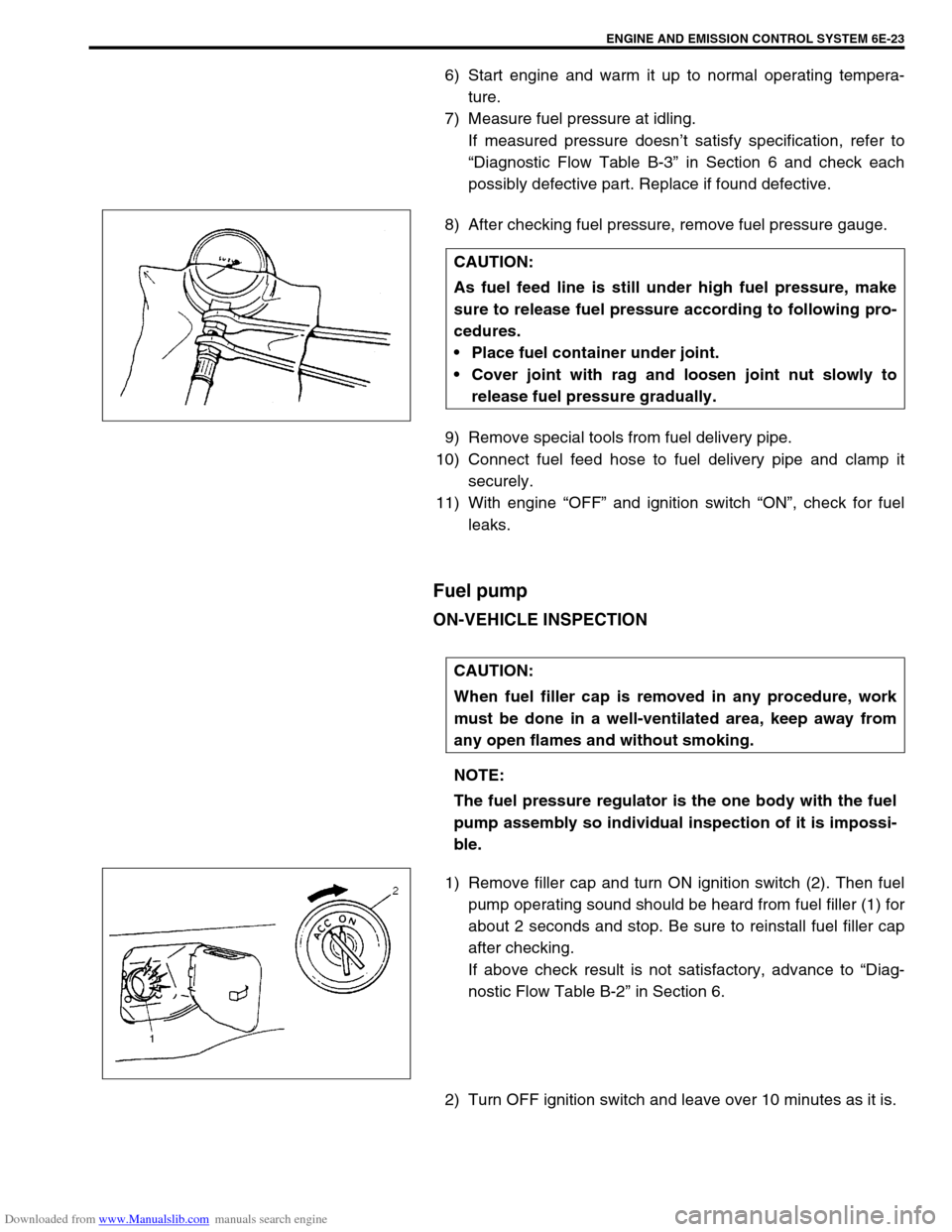
8) After checking fuel pressure, remove fuel pressure gauge.
9) Remove special tools from fuel delivery pipe.
10) Connect fuel feed hose to fuel delivery pipe and clamp it
securely.
11) With engine “OFF” and ignition switch “ON”, check for fuel
leaks.
Fuel pump
ON-VEHICLE INSPECTION
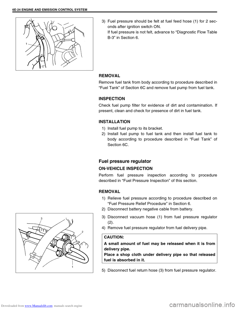
1) Remove filler cap and turn ON ignition switch (2). Then fuel
pump operating sound should be heard from fuel filler (1) for
about 2 seconds and stop. Be sure to reinstall fuel filler cap
after checking.
If above check result is not satisfactory, advance to “Diag-
nostic Flow Table B-2” in Section 6.
2) Turn OFF ignition switch and leave over 10 minutes as it is.CAUTION:
As fuel feed line is still under high fuel pressure, make
sure to release fuel pressure according to following pro-
cedures.
Place fuel container under joint.
Cover joint with rag and loosen joint nut slowly to
release fuel pressure gradually.
CAUTION:
When fuel filler cap is removed in any procedure, work
must be done in a well-ventilated area, keep away from
any open flames and without smoking.
NOTE:
The fuel pressure regulator is the one body with the fuel
pump assembly so individual inspection of it is impossi-
ble.
Page 629 of 687
Downloaded from www.Manualslib.com manuals search engine 6E-24 ENGINE AND EMISSION CONTROL SYSTEM
3) Fuel pressure should be felt at fuel feed hose (1) for 2 sec-
onds after ignition switch ON.
If fuel pressure is not felt, advance to “Diagnostic Flow Table
B-3” in Section 6.
REMOVAL
Remove fuel tank from body according to procedure described in
“Fuel Tank” of Section 6C and remove fuel pump from fuel tank.
INSPECTION
Check fuel pump filter for evidence of dirt and contamination. If
present, clean and check for presence of dirt in fuel tank.
INSTALLATION
1) Install fuel pump to its bracket.
2) Install fuel pump to fuel tank and then install fuel tank to
body according to procedure described in “Fuel Tank” of
Section 6C.
Fuel pressure regulator
ON-VEHICLE INSPECTION
Perform fuel pressure inspection according to procedure
described in “Fuel Pressure Inspection” of this section.
REMOVAL
1) Relieve fuel pressure according to procedure described on
“Fuel Pressure Relief Procedure” in Section 6.
2) Disconnect battery negative cable from battery.
3) Disconnect vacuum hose (1) from fuel pressure regulator
(2).
4) Remove fuel pressure regulator from fuel delivery pipe.
5) Disconnect fuel return hose (3) from fuel pressure regulator.
CAUTION:
A small amount of fuel may be released when it is from
delivery pipe.
Place a shop cloth under delivery pipe so that released
fuel is absorbed in it.
Page 631 of 687

Downloaded from www.Manualslib.com manuals search engine 6E-26 ENGINE AND EMISSION CONTROL SYSTEM
REMOVAL
1) Relieve fuel pressure according to procedure described in
“Fuel Pressure Relief Procedure” in Section 6.
2) Disconnect battery negative cable at battery.
3) Disconnect fuel injector couplers and release wire harness
from clamps.
4) Remove clamp bolt for fuel feed pipe and return pipe.
5) Remove fuel delivery pipe bolts (2).
6) Remove fuel injector(s) (3).
INSPECTION
1) Install injector (3) and fuel pressure regulator (4) to special
tool (injector checking tool).
Special tool
(A) : 09912-58421
2) Connect special tools (hose and attachment) to fuel feed
hose (1) of vehicle.
Special tool
(B) : 09912-58432
3) Connect special tool (test lead) to injector.
Special tool
(C) : 09930-88530
4) Install suitable vinyl tube onto injector nozzle to prevent fuel
from splashing out when injecting. CAUTION:
A small amount of fuel may come out after removal of
fuel injectors, cover them with shop cloth.
WARNING:
As fuel is injected in this inspection, perform in a well
ventilated area and away from open flames.
Use special care to prevent sparking when connecting
and disconnecting test lead to and from battery.
2. Fuel return line
Page 634 of 687
Downloaded from www.Manualslib.com manuals search engine ENGINE AND EMISSION CONTROL SYSTEM 6E-29
Electronic Control System
Engine control module (ECM)
REMOVAL
1) Disconnect battery negative cable at battery.
2) Disable air bag system, refer to “Disabling Air Bag System”
in Section 10B if equipped.
3) Remove glove box.
4) Disconnect ECM (1) and TCM (3) (if equipped) connectors.
5) Loosen 2 nuts (2) and remove ECM and TCM (if equipped).
INSTALLATION
1) Reverse removal procedure noting the following:
Connect connectors to ECM and TCM (if equipped)
securely.
Manifold absolute pressure sensor (MAP sensor)
INSPECTION
Check MAP sensor referring to “MAP Sensor Individual Check” in
DTC P0105 (No.11) Flow Table of Section 6. If malfunction is
found, replace.CAUTION:
As ECM consists of precision parts, be careful not to
expose it to excessive shock.
Page 635 of 687
Downloaded from www.Manualslib.com manuals search engine 6E-30 ENGINE AND EMISSION CONTROL SYSTEM
Throttle position sensor (TP sensor)
INSPECTION
1) Disconnect negative cable at battery and connector from TP
sensor.
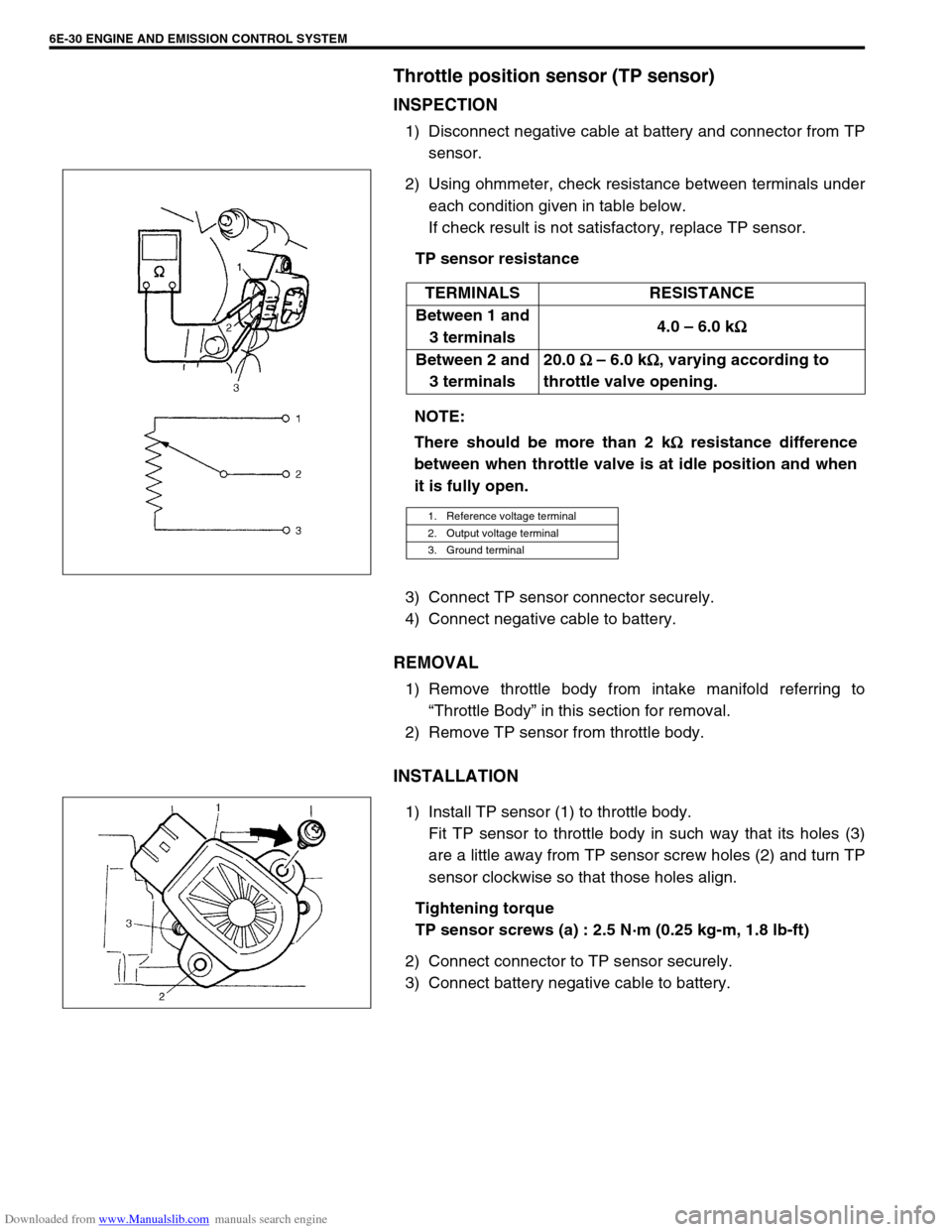
2) Using ohmmeter, check resistance between terminals under
each condition given in table below.
If check result is not satisfactory, replace TP sensor.
TP sensor resistance
3) Connect TP sensor connector securely.
4) Connect negative cable to battery.
REMOVAL
1) Remove throttle body from intake manifold referring to
“Throttle Body” in this section for removal.
2) Remove TP sensor from throttle body.
INSTALLATION
1) Install TP sensor (1) to throttle body.
Fit TP sensor to throttle body in such way that its holes (3)
are a little away from TP sensor screw holes (2) and turn TP
sensor clockwise so that those holes align.
Tightening torque
TP sensor screws (a) : 2.5 N·m (0.25 kg-m, 1.8 lb-ft)
2) Connect connector to TP sensor securely.
3) Connect battery negative cable to battery.TERMINALS RESISTANCE
Between 1 and
3 terminals4.0 – 6.0 k
Ω
ΩΩ Ω
Between 2 and
3 terminals20.0
Ω
ΩΩ Ω – 6.0 k
Ω
ΩΩ Ω, varying according to
throttle valve opening.
NOTE:
There should be more than 2 k
Ω
ΩΩ Ω resistance difference
between when throttle valve is at idle position and when
it is fully open.
1. Reference voltage terminal
2. Output voltage terminal
3. Ground terminal
Page 637 of 687
Downloaded from www.Manualslib.com manuals search engine 6E-32 ENGINE AND EMISSION CONTROL SYSTEM
Engine coolant temperature sensor (ECT sensor)
REMOVAL
1) Disconnect battery negative cable at battery.
2) Drain coolant referring to Step 6) of “Cooling System Flush
and Refill” in Section 6B.
3) Disconnect connector from ECT sensor.
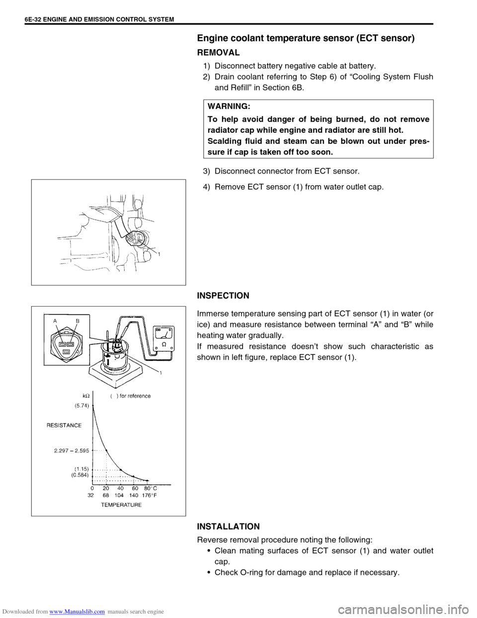
4) Remove ECT sensor (1) from water outlet cap.
INSPECTION
Immerse temperature sensing part of ECT sensor (1) in water (or
ice) and measure resistance between terminal “A” and “B” while
heating water gradually.
If measured resistance doesn’t show such characteristic as
shown in left figure, replace ECT sensor (1).
INSTALLATION
Reverse removal procedure noting the following:
Clean mating surfaces of ECT sensor (1) and water outlet
cap.
Check O-ring for damage and replace if necessary. WARNING:
To help avoid danger of being burned, do not remove
radiator cap while engine and radiator are still hot.
Scalding fluid and steam can be blown out under pres-
sure if cap is taken off too soon.
Page 638 of 687
Downloaded from www.Manualslib.com manuals search engine ENGINE AND EMISSION CONTROL SYSTEM 6E-33
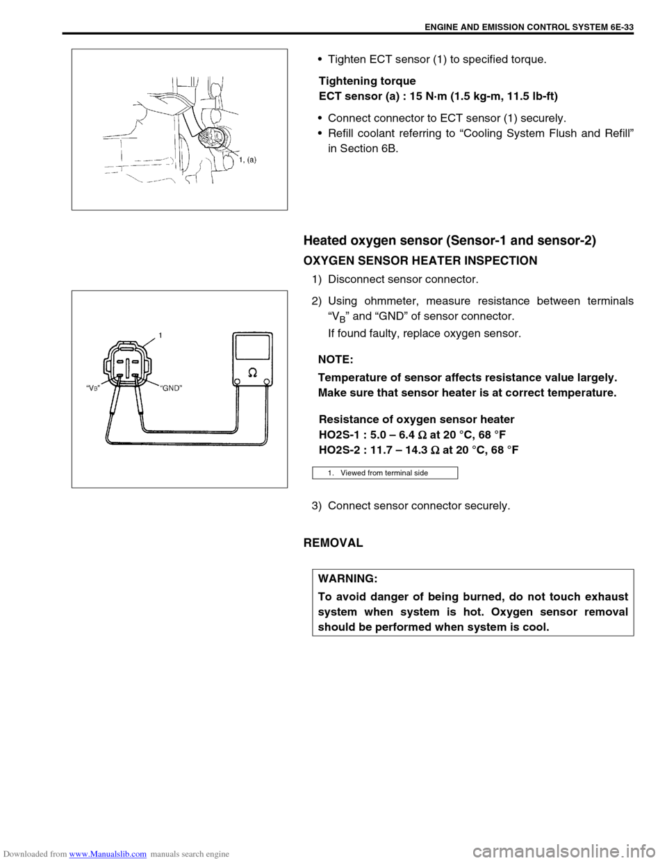
Tighten ECT sensor (1) to specified torque.
Tightening torque
ECT sensor (a) : 15 N·m (1.5 kg-m, 11.5 lb-ft)
Connect connector to ECT sensor (1) securely.
Refill coolant referring to “Cooling System Flush and Refill”
in Section 6B.
Heated oxygen sensor (Sensor-1 and sensor-2)
OXYGEN SENSOR HEATER INSPECTION
1) Disconnect sensor connector.
2) Using ohmmeter, measure resistance between terminals
“V
B” and “GND” of sensor connector.
If found faulty, replace oxygen sensor.
Resistance of oxygen sensor heater
HO2S-1 : 5.0 – 6.4
Ω
ΩΩ Ω at 20 °C, 68 °F
HO2S-2 : 11.7 – 14.3
Ω
ΩΩ Ω at 20 °C, 68 °F
3) Connect sensor connector securely.
REMOVAL
NOTE:
Temperature of sensor affects resistance value largely.
Make sure that sensor heater is at correct temperature.
1. Viewed from terminal side
WARNING:
To avoid danger of being burned, do not touch exhaust
system when system is hot. Oxygen sensor removal
should be performed when system is cool.