Page 180 of 687
Downloaded from www.Manualslib.com manuals search engine FRONT SUSPENSION 3D-7
4WD
→ 2WD
When the transfer shift control lever is shifted from the 4WD (4H or 4L) to the 2WD (2H) position, the 4WD con-
troller activates VSV1 and the intake manifold vacuum is applied to the chamber “A” in the hub housing. As the
slide gear is shifted to the wheel side by the vacuum force and disengaged from the outer gear, rotation of the
front wheel hub is not transmitted to the front axle shaft.
1. EPI & A/C controller 8. Engine speed signal 15. Chamber A 22. Slide gear
2. 4WD controller 9. Intake manifold 16. Piston A 23. Wheel hub
3. 4WD indicator lamp 10. Check valve 17. Magnet 24. Spindle
4.4WD switch 11. Vacuum tank 18. Housing 25. Front axle shaft
5. A/C switch (if equipped) 12. VSV1 19. Spring 26. To opposite side
6. Vacuum switch 13. VSV2 20. Diaphragm 27. A/C controller
7. A/C cut signal (if equipped) 14. Outer gear 21. Sleeve A: Vacuum circuit
Page 183 of 687

Downloaded from www.Manualslib.com manuals search engine 3D-10 FRONT SUSPENSION
4WD Controller and ITS Circuit Check
VOLTAGE CHECK
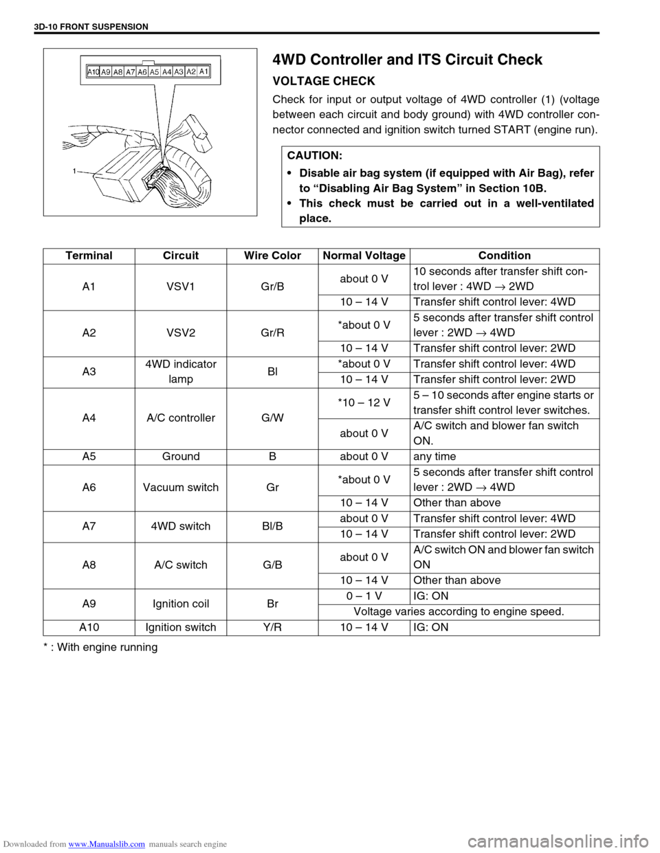
Check for input or output voltage of 4WD controller (1) (voltage
between each circuit and body ground) with 4WD controller con-
nector connected and ignition switch turned START (engine run).
* : With engine runningCAUTION:
Disable air bag system (if equipped with Air Bag), refer
to “Disabling Air Bag System” in Section 10B.
This check must be carried out in a well-ventilated
place.
Terminal Circuit Wire Color Normal Voltage Condition
A1 VSV1 Gr/Babout 0 V10 seconds after transfer shift con-
trol lever : 4WD → 2WD
10 – 14 V Transfer shift control lever: 4WD
A2 VSV2 Gr/R*about 0 V5 seconds after transfer shift control
lever : 2WD → 4WD
10 – 14 V Transfer shift control lever: 2WD
A34WD indicator
lampBl*about 0 V Transfer shift control lever: 4WD
10 – 14 V Transfer shift control lever: 2WD
A4 A/C controller G/W*10 – 12 V5 – 10 seconds after engine starts or
transfer shift control lever switches.
about 0 VA/C switch and blower fan switch
ON.
A5 Ground B about 0 V any time
A6 Vacuum switch Gr*about 0 V5 seconds after transfer shift control
lever : 2WD → 4WD
10 – 14 V Other than above
A7 4WD switch Bl/Babout 0 V Transfer shift control lever: 4WD
10 – 14 V Transfer shift control lever: 2WD
A8 A/C switch G/Babout 0 VA/C switch ON and blower fan switch
ON
10 – 14 V Other than above
A9 Ignition coil Br0 – 1 V IG: ON
Voltage varies according to engine speed.
A10 Ignition switch Y/R 10 – 14 V IG: ON
Page 209 of 687
Downloaded from www.Manualslib.com manuals search engine 3D-36 FRONT SUSPENSION
Leading Arm / Bushing
REMOVAL
1) Hoist vehicle.
2) Remove air locking hub vacuum pipe clamp bolts (2) (for
4WD).
3) Support front axle housing by using floor jack.
4) Remove shock absorber lower mounting bolt, refer to “Front
Shock Absorber” in this section.
5) Remove mounting bolts and leading arm (1).
6) Remove bushings by using hydraulic press and special
tools.
Special tool
(A) : 09924-74510
(B) : 09951-16030
(C) : 09951-26010
1. Leading arm (right side)
Page 210 of 687

Downloaded from www.Manualslib.com manuals search engine FRONT SUSPENSION 3D-37
INSTALLATION
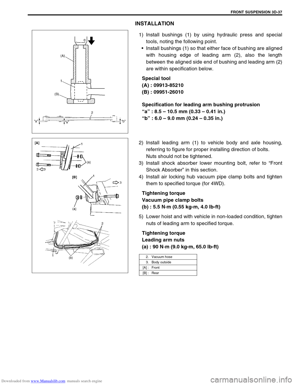
1) Install bushings (1) by using hydraulic press and special
tools, noting the following point.
Install bushings (1) so that either face of bushing are aligned
with housing edge of leading arm (2), also the length
between the aligned side end of bushing and leading arm (2)
are within specification below.
Special tool
(A) : 09913-85210
(B) : 09951-26010
Specification for leading arm bushing protrusion
“a” : 8.5 – 10.5 mm (0.33 – 0.41 in.)
“b” : 6.0 – 9.0 mm (0.24 – 0.35 in.)
2) Install leading arm (1) to vehicle body and axle housing,
referring to figure for proper installing direction of bolts.
Nuts should not be tightened.
3) Install shock absorber lower mounting bolt, refer to “Front
Shock Absorber” in this section.
4) Install air locking hub vacuum pipe clamp bolts and tighten
them to specified torque (for 4WD).
Tightening torque
Vacuum pipe clamp bolts
(b) : 5.5 N·m (0.55 kg-m, 4.0 lb-ft)
5) Lower hoist and with vehicle in non-loaded condition, tighten
nuts of leading arm to specified torque.
Tightening torque
Leading arm nuts
(a) : 90 N·m (9.0 kg-m, 65.0 lb-ft)
2. Vacuum hose
3. Body outside
[A] : Front
[B] : Rear
Page 214 of 687

Downloaded from www.Manualslib.com manuals search engine FRONT SUSPENSION 3D-41
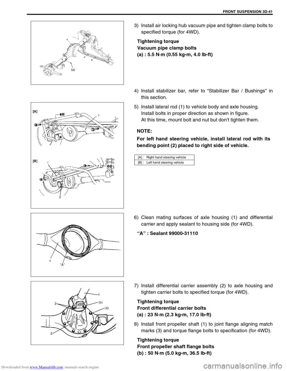
3) Install air locking hub vacuum pipe and tighten clamp bolts to
specified torque (for 4WD).
Tightening torque
Vacuum pipe clamp bolts
(a) : 5.5 N·m (0.55 kg-m, 4.0 lb-ft)
4) Install stabilizer bar, refer to “Stabilizer Bar / Bushings” in
this section.
5) Install lateral rod (1) to vehicle body and axle housing.
Install bolts in proper direction as shown in figure.
At this time, mount bolt and nut but don't tighten them.
6) Clean mating surfaces of axle housing (1) and differential
carrier and apply sealant to housing side (for 4WD).
“A” : Sealant 99000-31110
7) Install differential carrier assembly (2) to axle housing and
tighten carrier bolts to specified torque (for 4WD).
Tightening torque
Front differential carrier bolts
(a) : 23 N·m (2.3 kg-m, 17.0 lb-ft)
8) Install front propeller shaft (1) to joint flange aligning match
marks (3) and torque flange bolts to specification (for 4WD).
Tightening torque
Front propeller shaft flange bolts
(b) : 50 N·m (5.0 kg-m, 36.5 lb-ft)
NOTE:
For left hand steering vehicle, install lateral rod with its
bending point (2) placed to right side of vehicle.
[A] : Right hand steering vehicle
[B] : Left hand steering vehicle
Page 217 of 687

Downloaded from www.Manualslib.com manuals search engine 3D-44 FRONT SUSPENSION
Tightening Torque Specifications
Required Service Material
Fastening partTightening torque
Nm kg-m lb-ft
Stabilizer mount bracket bolt 20 2.0 14.5
Stabilizer ball joint nut 50 5.0 36.5
Shock absorber lock nut 29 2.9 21.0
Shock absorber lower nut 90 9.0 65.0
Brake caliper carrier bolt 85 8.5 61.5
Wheel bearing lock nut 220 22.0 160.0
Wheel bearing lock washer screw 1.5 0.15 1.0
Air locking hub bolt 48 4.8 35.0
Wheel spindle bolt 50 5.0 36.5
Kingpin bolt 25 2.5 18.0
Knuckle seal cover bolt 10 1.0 7.5
Tie-rod end nut
43 4.3 31.5
Drag-rod end nut (Knuckle side)
Lateral rod bolt and nut
90 9.0 65.0
Leading arm nut
Front differential carrier bolt 23 2.3 17.0
Front propeller shaft flange bolt 50 5.0 36.5
Wheel nut 95 9.5 69.0
Vacuum pipe clamp bolt 5.5 0.55 4.0
MaterialRecommended SUZUKI product
(Part Number)Use
Lithium grease SUZUKI SUPER GREASE (A)
(99000-25010)Knuckle seal / axle shaft oil seal
Recess of wheel spindles
Wheel hub oil seal
Wheel bearing
Spindle thrust washer
Spindle bush (inside and flange
part)
Spindle oil seal
SUZUKI SUPER GREASE (C)
(99000-25030)Kingpin bearing
Axle shaft joint (for 4WD)
Sealant SUZUKI BOND NO. 1215
(99000-31110)Mating surfaces of wheel spindle
and knuckle
Mating surface of differential carrier
and axle housing
Sealing compound SUZUKI SEALING COMPOUND
366E
(99000-31090)Mating surface of wheel spindle and
knuckle
Kingpin
Mating surfaces of hub cap and
wheel hub
Page 229 of 687
Downloaded from www.Manualslib.com manuals search engine 3E-10 REAR SUSPENSION
INSTALLATION
1) Install lateral rod to vehicle body and rear axle housing.
Tighten bolt and nut temporarily by hand.
2) Lower hoist and with vehicle in non-loaded condition, tighten
lateral rod bolt and nut to specified torque.
Tightening torque
Lateral rod bolt and nut
(a) : 90 N·m (9.0 kg-m, 65.0 lb-ft)
Trailing Arm / Bushing
REMOVAL
1) Hoist vehicle.
2) Support rear axle housing (1) by using floor jack (2).
3) Disconnect parking brake cable clamp (1) from trailing arm.
4) Disconnect wheel speed sensor harness clamps (2) from
trailing arm (if equipped with ABS).
5) Remove trailing arm mounting bolts.
6) Remove trailing arm (1).
Page 231 of 687

Downloaded from www.Manualslib.com manuals search engine 3E-12 REAR SUSPENSION
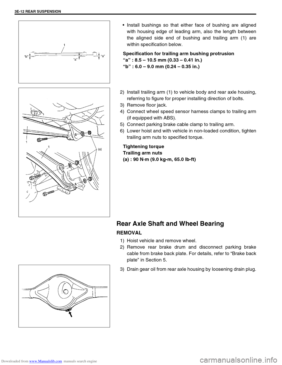
Install bushings so that either face of bushing are aligned
with housing edge of leading arm, also the length between
the aligned side end of bushing and trailing arm (1) are
within specification below.
Specification for trailing arm bushing protrusion
“a” : 8.5 – 10.5 mm (0.33 – 0.41 in.)
“b” : 6.0 – 9.0 mm (0.24 – 0.35 in.)
2) Install trailing arm (1) to vehicle body and rear axle housing,
referring to figure for proper installing direction of bolts.
3) Remove floor jack.
4) Connect wheel speed sensor harness clamps to trailing arm
(if equipped with ABS).
5) Connect parking brake cable clamp to trailing arm.
6) Lower hoist and with vehicle in non-loaded condition, tighten
trailing arm nuts to specified torque.
Tightening torque
Trailing arm nuts
(a) : 90 N·m (9.0 kg-m, 65.0 lb-ft)
Rear Axle Shaft and Wheel Bearing
REMOVAL
1) Hoist vehicle and remove wheel.
2) Remove rear brake drum and disconnect parking brake
cable from brake back plate. For details, refer to “Brake back
plate” in Section 5.
3) Drain gear oil from rear axle housing by loosening drain plug.