Page 59 of 687
Downloaded from www.Manualslib.com manuals search engine 1A-6 HEATER AND VENTILATION
4) Disconnect blower fan switch coupler and A/C switch coupler
(if equipped)
5) Disconnect each heater control cables.
6) Remove heater control lever assembly (1).
7) Remove blower fan switch screw (3).
8) Remove blower fan switch (2) as shown figure.
INSTALLATION
1) Install in reverse order of removal procedure, adjustment the
following items.
Move control lever fully in arrow direction
Push heater lever and air inlet box lever fully in arrow direc-
tion and fix cable with clamp in position as shown figure.
2) If equipped with air bag, enable air bag system. Refer to
“Enabling Air Bag System” in Section 10B.
1. Heater control lever assembly
NOTE:
After installing control cables, be sure that control levers
move smoothly and stop at proper position.
1. Heater unit
2. Air inlet box
3. Mode control cable
4. Temperature control cable
5. Fresh air control cable
Page 68 of 687

Downloaded from www.Manualslib.com manuals search engine AIR CONDITIONING (OPTIONAL) 1B-7
Abnormal Noise Diagnosis
There are various types of noise, ranging from those produced in the engine compartment to those from the
passenger compartment, also from rumbling noises to whistling noises.
Abnormal noise from compressor
Abnormal noise from magnetic clutch
Abnormal noise from tubing
Abnormal noise from condenser
Condition Possible Cause Correction
During compressor
operation, a rumbling
noise is heard propor-
tional to engine revo-
lutions.Inadequate clearance in piston area (piston or
swash-plate).Repair or replace compressor as
necessary
A loud noise is heard
at a certain rpm, dis-
proportionately to
engine revolution.Loose or faulty compressor drive belt. Adjust drive belt tension, or replace
belt.
Loose compressor mounting bolts. Retighten mounting bolts.
A loud rattle is heard
at low engine rpm.Loose compressor clutch plate bolt. Retighten clutch plate bolt.
Replace compressor if it was oper-
ated in this condition for a long
time.
Condition Possible Cause Correction
A rumbling noise is
heard when compres-
sor is not operating.Worn or damaged bearings. Replace magnet clutch assembly.
A chattering noise is
heard when compres-
sor is engaged.Faulty clutch clearance (excessive). Adjust clutch clearance.
Worn clutch friction surface. Replace magnet clutch assembly.
Compressor oil leaked from lip type seal. Replace lip type seal.
Contaminating the friction surface. Replace compressor body assem-
bly.
Condition Possible Cause Correction
A droning noise is
heard inside vehicle,
but not particularly
noticeable in engine
compartment.Faulty tubing clamps. Reposition clamps or increase the
number of clamps.
Resonance caused by pulsation from variations
in refrigerant pressure.Attach a silencer to tubing, or mod-
ify its position and length.
Condition Possible Cause Correction
Considerable vibra-
tion in condenser.Resonance from condenser bracket and body. Firmly insert a silencer between
condenser bracket and body.
Page 100 of 687

Downloaded from www.Manualslib.com manuals search engine AIR CONDITIONING (OPTIONAL) 1B-39
A/C Switch
REMOVAL AND INSTALLATION
Refer to “Heater Control Lever Assembly” in Section 1A.
INSPECTION
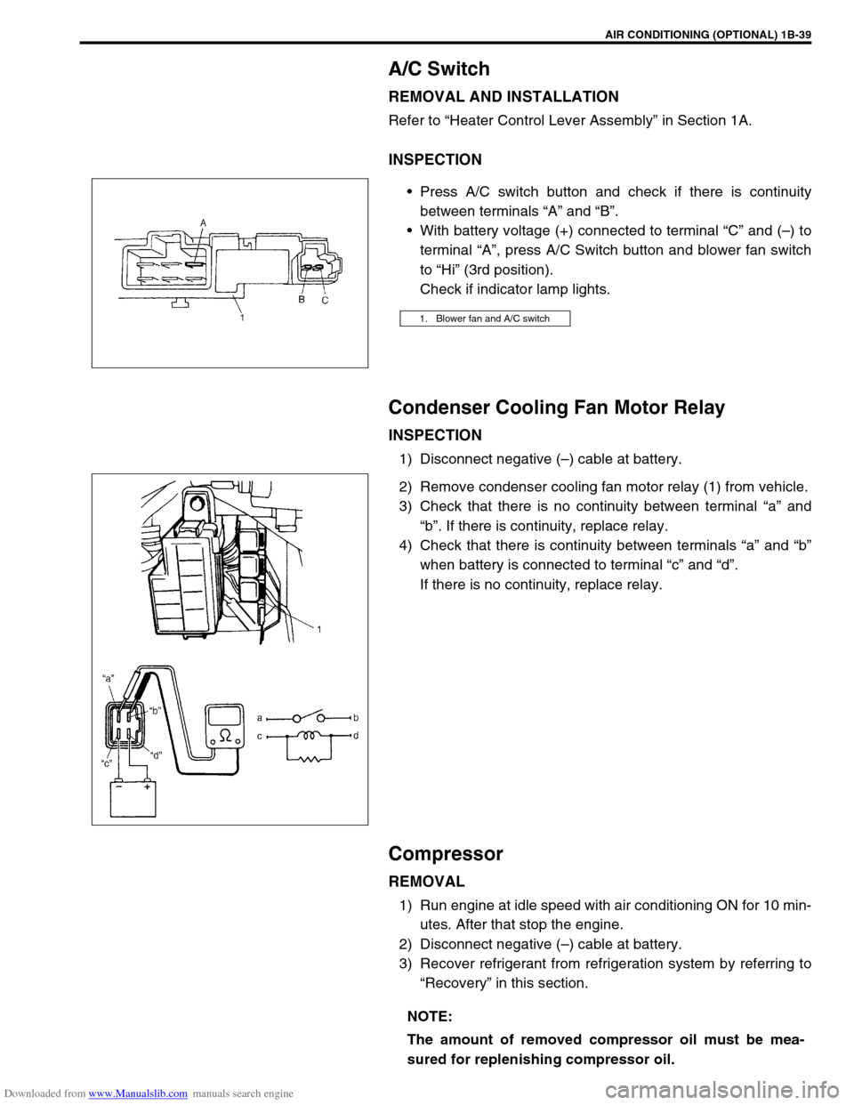
Press A/C switch button and check if there is continuity
between terminals “A” and “B”.
With battery voltage (+) connected to terminal “C” and (–) to
terminal “A”, press A/C Switch button and blower fan switch
to “Hi” (3rd position).
Check if indicator lamp lights.
Condenser Cooling Fan Motor Relay
INSPECTION
1) Disconnect negative (–) cable at battery.
2) Remove condenser cooling fan motor relay (1) from vehicle.
3) Check that there is no continuity between terminal “a” and
“b”. If there is continuity, replace relay.
4) Check that there is continuity between terminals “a” and “b”
when battery is connected to terminal “c” and “d”.
If there is no continuity, replace relay.
Compressor
REMOVAL
1) Run engine at idle speed with air conditioning ON for 10 min-
utes. After that stop the engine.
2) Disconnect negative (–) cable at battery.
3) Recover refrigerant from refrigeration system by referring to
“Recovery” in this section.
1. Blower fan and A/C switch
NOTE:
The amount of removed compressor oil must be mea-
sured for replenishing compressor oil.
Page 104 of 687
Downloaded from www.Manualslib.com manuals search engine AIR CONDITIONING (OPTIONAL) 1B-43
4) Remove circlip (1) using special tool.
Special tool
(A) : 09900-06107
5) Remove magnet clutch lead wire clamp screw, and discon-
nect magnet clutch lead wire.
6) Remove magnet clutch pulley (1) by using a puller (2).
7) Remove snap ring (1) using special tool.
Special tool
(A) : 09900-06107
8) Remove magnet clutch coil (2) from compressor body
assembly (3).
INSTALLATION
1) Install magnet clutch coil (1).
2) Install snap ring (3) to proper direction as show using special
tool.
Special tool
(A) : 09900-06107
NOTE:
Be careful not to damage pulley part.
NOTE:
Protrusion on under side of magnet clutch coil (1) must
match hole in compressor body assembly (2).
Page 157 of 687

Downloaded from www.Manualslib.com manuals search engine 3C-4 STEERING WHEEL AND COLUMN
Drive Air Bag (Inflator) Module (For Vehicle
with Air Bag System)
REMOVAL
1) Disconnect negative battery cable at battery terminal.
2) Disable air bag system. Refer to “Disabling Air Bag System”
in Section 10B.
3) Remove steering wheel side cap (1) of left side.
4) Loosen 2 bolts (2) mounting driver air bag (inflator) module
till it turns freely, pull them out and fix them to bolt clamps (3).
5) Remove driver air bag (inflator) module (1) from steering
wheel.
6) Disconnect yellow connector (2) in order a) – b) as shown.
INSPECTION
WARNING:
When handling an air bag (inflator) module, be sure to
read “Service Precautions” given earlier in this section
and observe each instruction. Failure to follow them
could cause a damage to the air bag (inflator) module or
result in personal injury.
WARNING:
Never disassemble driver air bag (inflator) module or
measure its resistance. Otherwise, personal injury may
result.
CAUTION:
If air bag (inflator) module was dropped from a height of
90 cm (3 ft) or more, it should be replaced.
Page 177 of 687
Downloaded from www.Manualslib.com manuals search engine 3D-4 FRONT SUSPENSION
SYSTEM CIRCUIT
1. 4WD controller 4. 4WD indicator lamp 7. Blower fan switch 10. Vacuum switch 13. IG fuse
2. VSV1 5. ECM 8. A/C switch (if equipped) 11. Main fuse 14. A/C controller (if equipped)
3. VSV2 6. Blower fan motor 9. 4WD switch 12. IG switch 15. Coupler of 4WD controller
Page 178 of 687

Downloaded from www.Manualslib.com manuals search engine FRONT SUSPENSION 3D-5
Components and Functions
Component Function
4WD switch When the transfer shift lever is shifted to 4L or 4H position from 2H, this switch
turns ON and cause the 4WD control system to turn ON.
4WD controller When the 4WD switch turns on, the 4WD controller activates VSV2 to lock the
air locking hubs and when it receives an “ON” signal from the vacuum switch, it
makes VSV2 to complete operation within 5 seconds and causes the 4WD indi-
cator light to light up.
If vacuum in the vacuum circuit fails to reach the specified level due to a leakage
in the vacuum circuit (when no “ON” signal is inputted from the vacuum switch),
the 4WD controller stops operation of VSV2 in 15 seconds and makes the 4WD
indicator light to flash to warn occurrence of a trouble.
When the 4WD switch turns off, the 4WD controller activates VSV1 for 10 sec-
onds to unlock the hubs and at the same time makes the 4WD indicator light
turn off.
VSV1 VSV1 operates according to the signal from the 4WD controller. When it is acti-
vated, the port opens and vacuum in the intake manifold is applied through the
vacuum circuit to unlock to the slide gear in the air locking hub. As a result, the
air locking hubs are unlocked.
VSV2 VSV2 operates according to the signal from the 4WD controller. When it is acti-
vated, the port opens and vacuum in the intake manifold is applied through the
vacuum circuit to lock to the slide gear in the air locking hub. As a result, the air
locking hubs are locked.
Vacuum switch When VSV2 receives the “ON” signal from 4WD switch, vacuum is applied
through its circuit to the vacuum switch. The vacuum switch turns on when it
detects vacuum exceeding 260 mmHg.
“4WD” indicator lamp It lights up when 4WD control system is in the 4WD mode.
It flashes to warn that locking hub operation has not completed (4WD control
system fails to shift 4WD).
Page 179 of 687

Downloaded from www.Manualslib.com manuals search engine 3D-6 FRONT SUSPENSION
OPERATION
2WD
→ 4WD
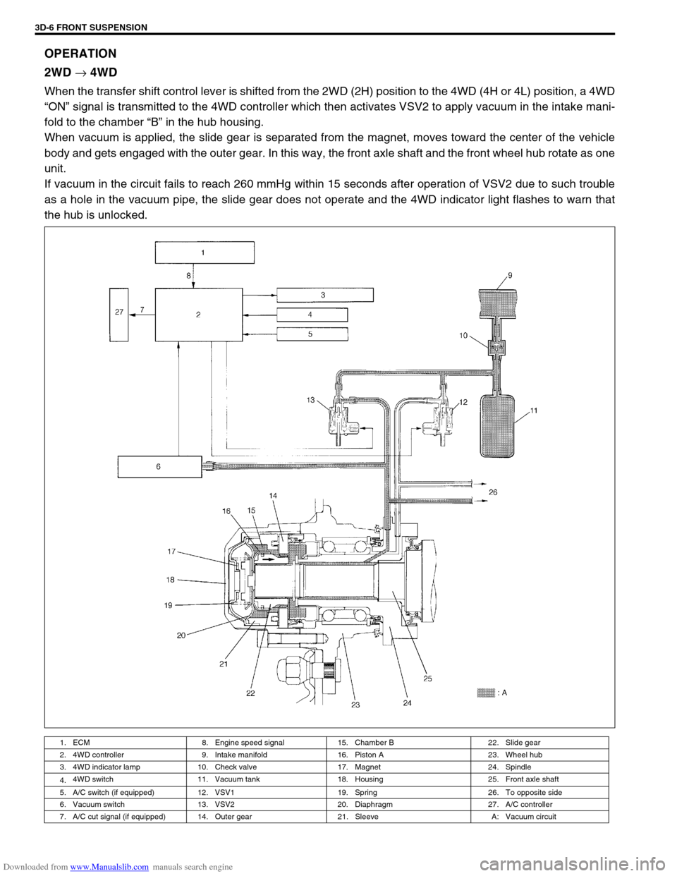
When the transfer shift control lever is shifted from the 2WD (2H) position to the 4WD (4H or 4L) position, a 4WD
“ON” signal is transmitted to the 4WD controller which then activates VSV2 to apply vacuum in the intake mani-
fold to the chamber “B” in the hub housing.
When vacuum is applied, the slide gear is separated from the magnet, moves toward the center of the vehicle
body and gets engaged with the outer gear. In this way, the front axle shaft and the front wheel hub rotate as one
unit.
If vacuum in the circuit fails to reach 260 mmHg within 15 seconds after operation of VSV2 due to such trouble
as a hole in the vacuum pipe, the slide gear does not operate and the 4WD indicator light flashes to warn that
the hub is unlocked.
1. ECM 8. Engine speed signal 15. Chamber B 22. Slide gear
2. 4WD controller 9. Intake manifold 16. Piston A 23. Wheel hub
3. 4WD indicator lamp 10. Check valve 17. Magnet 24. Spindle
4.4WD switch 11. Vacuum tank 18. Housing 25. Front axle shaft
5. A/C switch (if equipped) 12. VSV1 19. Spring 26. To opposite side
6. Vacuum switch 13. VSV2 20. Diaphragm 27. A/C controller
7. A/C cut signal (if equipped) 14. Outer gear 21. Sleeve A: Vacuum circuit