Page 4 of 687

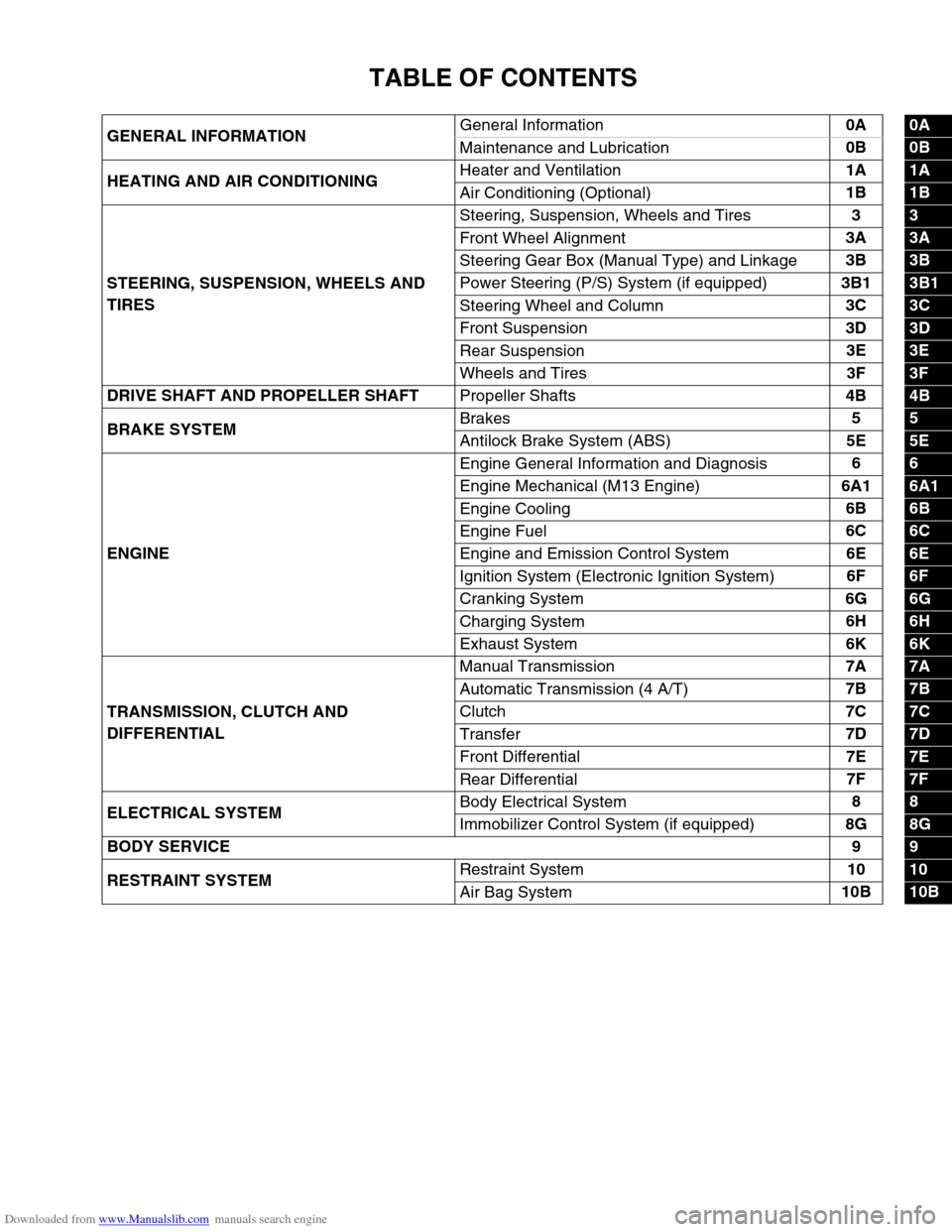
Downloaded from www.Manualslib.com manuals search engine TABLE OF CONTENTS
GENERAL INFORMATIONGeneral Information0A0A
Maintenance and Lubrication0B
0B
HEATING AND AIR CONDITIONINGHeater and Ventilation1A
1A
Air Conditioning (Optional)1B
1B
STEERING, SUSPENSION, WHEELS AND
TIRESSteering, Suspension, Wheels and Tires3
3
Front Wheel Alignment3A
3A
Steering Gear Box (Manual Type) and Linkage3B
3B
Power Steering (P/S) System (if equipped)3B1
3B1
Steering Wheel and Column3C
3C
Front Suspension3D
3D
Rear Suspension3E
3E
Wheels and Tires3F
3F
DRIVE SHAFT AND PROPELLER SHAFT
Propeller Shafts4B
4B
BRAKE SYSTEMBrakes5
5
Antilock Brake System (ABS)5E
5E
ENGINEEngine General Information and Diagnosis6
6
Engine Mechanical (M13 Engine)6A1
6A1
Engine Cooling6B
6B
Engine Fuel6C
6C
Engine and Emission Control System6E
6E
Ignition System (Electronic Ignition System)6F
6F
Cranking System6G
6G
Charging System6H
6H
Exhaust System6K
6K
TRANSMISSION, CLUTCH AND
DIFFERENTIALManual Transmission7A
7A
Automatic Transmission (4 A/T)7B
7B
Clutch7C
7C
Transfer7D
7D
Front Differential7E
7E
Rear Differential7F
7F
ELECTRICAL SYSTEMBody Electrical System8
8
Immobilizer Control System (if equipped)8G
8G
BODY SERVICE9
9
RESTRAINT SYSTEMRestraint System10
10
Air Bag System10B
10B
Page 24 of 687
Downloaded from www.Manualslib.com manuals search engine GENERAL INFORMATION 0A-19
Vehicle Lifting Points
When Using Frame Contact Hoist
WARNING:
Before applying hoist to underbody, always take vehicle balance throughout service into consider-
ation. Vehicle balance on hoist may change depending on what part to be removed.
Before lifting up the vehicle, check to be sure that end of hoist arm is not in contact with brake pipe,
fuel pipe, bracket or any other part.
When using frame contact hoist, apply hoist as shown (right and left at the same position). Lift up
the vehicle till 4 tires are a little off the ground and make sure that the vehicle will not fall off by try-
ing to move vehicle body in both ways. Work can be started only after this confirmation.
Make absolutely sure to lock hoist after vehicle is hoisted up.
1. Front lifting point
2. Rear lifting point
3. Front
Page 43 of 687

Downloaded from www.Manualslib.com manuals search engine 0B-12 MAINTENANCE AND LUBRICATION
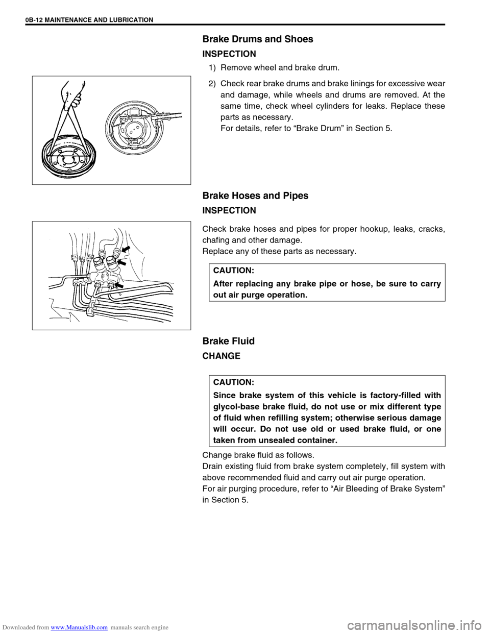
Brake Drums and Shoes
INSPECTION
1) Remove wheel and brake drum.
2) Check rear brake drums and brake linings for excessive wear
and damage, while wheels and drums are removed. At the
same time, check wheel cylinders for leaks. Replace these
parts as necessary.
For details, refer to “Brake Drum” in Section 5.
Brake Hoses and Pipes
INSPECTION
Check brake hoses and pipes for proper hookup, leaks, cracks,
chafing and other damage.
Replace any of these parts as necessary.
Brake Fluid
CHANGE
Change brake fluid as follows.
Drain existing fluid from brake system completely, fill system with
above recommended fluid and carry out air purge operation.
For air purging procedure, refer to “Air Bleeding of Brake System”
in Section 5.
CAUTION:
After replacing any brake pipe or hose, be sure to carry
out air purge operation.
CAUTION:
Since brake system of this vehicle is factory-filled with
glycol-base brake fluid, do not use or mix different type
of fluid when refilling system; otherwise serious damage
will occur. Do not use old or used brake fluid, or one
taken from unsealed container.
Page 53 of 687
Downloaded from www.Manualslib.com manuals search engine 0B-22 MAINTENANCE AND LUBRICATION
Recommended Fluids and Lubricants
Engine oilSE, SF, SG, SH, SJ or SL
(Refer to “Engine Oil and Oil Filter” in this section for engine oil viscos-
ity.)
Engine coolant
(Ethylene glycol base coolant)“Antifreeze/Anticorrosion coolant”
Brake fluid DOT 3
Manual transmission oil Refer to “Maintenance Service” in Section 7A.
Transfer oil Refer to “Oil Change” in Section 7D.
Differential oil (front & rear) Refer to “Oil Change” in Section 7E and 7F.
Automatic transmission fluid
An equivalent of DEXRON
®-IIE or DEXRON®-III
Power steering fluid
An equivalent of DEXRON
®-II, DEXRON®-IIE or DEXRON®-III
Clutch linkage pivot points
Water resistance chassis grease
(SUZUKI SUPER GREASE A 99000-25010)
Steering knuckle seal
Door hinges
Engine oil or water resistance chassis grease
Hood latch assembly
Key lock cylinder Spray lubricant
Page 111 of 687

Downloaded from www.Manualslib.com manuals search engine 3-2 STEERING, SUSPENSION, WHEELS AND TIRES
General Diagnosis
Since the problems in steering, suspension, wheels and tires involve several systems, they must all be consid-
ered when diagnosing a complaint. To avoid using the wrong symptom, always road test the vehicle first.
Proceed with the following preliminary inspections and correct any defects which are found.
1) Inspect tires for proper pressure and uneven wear.
2) Raise vehicle on a hoist and inspect front and rear suspension and steering system for loose or damaged
parts.
3) Spin front wheel. Inspect for out-of-round tires, out-of-balance tires, bent rims, loose and/or rough wheel
bearings.
Diagnosis Table
Condition Possible Cause Correction
Vehicle Pulls (Leads)
Mismatched or uneven tires Replace tire.
Tires not adequately inflated Adjust tire pressure.
Broken or sagging springs Replace spring.
Radial tire lateral force Replace tire.
Disturbed front wheel alignment Check and adjust wheel alignment.
Disturbed rear wheel alignment Check and adjust wheel alignment.
Brake dragging in one road wheel Repair front brake.
Loose, bent or broken front or rear suspension
partsTighten or replace suspension part.
Abnormal or
Excessive Tire WearSagging or broken springs Replace spring.
Tire out of balance Adjust balance or replace tire.
Disturbed front wheel alignment Check wheel alignment.
Faulty shock absorber Replace shock absorber.
Hard driving Replace tire.
Overloaded vehicle Replace tire.
Not rotating tire Replace or rotate tire.
Worn or loose road wheel bearings Replace wheel bearing.
Wobbly wheel or tires Replace wheel or tire.
Tires not adequately inflated Adjust the pressure.
Wheel Tramp
Blister or bump on tire Replace tire.
Improper shock absorber action Replace shock absorber.
Page 116 of 687

Downloaded from www.Manualslib.com manuals search engine STEERING, SUSPENSION, WHEELS AND TIRES 3-7
Radial Tire Lead
“Lead” is the deviation of the vehicle from a straight path on a level rod even with no pressure on the steering
wheel.
Lead is usually caused by:
1) Incorrect alignment.
2) Uneven brake adjustment.
3) Tire construction.
The way in which a tire is built can produce lead in a vehicle. An example of this is placement of the belt. Off
center belts on radial tires can cause the tire to develop a side force while rolling straight down the road. If one
side of the tire has a little larger diameter than the other, the tire will tend to roll to one side. This will develop a
side force which can produce vehicle lead.
The procedure in above figure (Lead Diagnosis) should be used to make sure that front alignment is not mis-
taken for tire lead.
1) Part of the lead diagnosis procedure is different from the proper tire rotation pattern currently in the owner
and service manuals. If a medium to high mileage tire is moved to the other side of the vehicle, be sure to
check that ride roughness has not developed.
2) Rear tires will not cause lead.
Vibration Diagnosis
Wheel unbalance causes most of the highway speed vibration problems. If a vibration remains after dynamic
balancing, its possible causes are as follows.
1) Tire runout.
2) Wheel runout.
3) Tire stiffness variation.
Measuring tire and/or wheel free runout will uncover only part of the problem. All three causes, known as loaded
radial runout, must be checked by using a Tire Problem Detector (TPD). If TPD is not available, alternative
method of substituting known good tire and wheel assemblies on the problem vehicle can be used, although it
takes a longer time.
[A] : Tire out of round 1. Smooth road
[B] : Tire stiffness variation 2. Suspension movement (loaded runout)
[C] : Rim bent or out of round
Page 221 of 687
Downloaded from www.Manualslib.com manuals search engine 3E-2 REAR SUSPENSION
General Description
1. Rear axle housing 4. Bearing oil seal 7. Brake drum 10. Bump stopper
2. Rear wheel bearing 5. Oil seal protector 8. Rear axle shaft 11. Coil spring
3. Bearing retainer ring 6. Lateral rod 9. Shock absorber 12. Trailing arm
Page 223 of 687

Downloaded from www.Manualslib.com manuals search engine 3E-4 REAR SUSPENSION
Rear Suspension Fasteners
Check each bolt and nut fastening suspension parts for tightness.
Tighten loose one, if any, to specified torque, referring to “Tighten-
ing Torque Specifications” of this section.
Bearing Retainer and Axle Shaft Oil Seal
Check
When brake drum has been removed, check inside of brake
drum for gear oil leakage.
Also, check backside of brake back plate for oil leakage.If oil
leakage is found, replace defective oil seal.
Whenever it is possible to check oil seal during disassembly,
check its lip for wear.
If oil leakage or worn lip is found, replace defective oil seal.
Bump Stopper and Spring Rubber Seat Check
Inspect for wear and breakage. If found defective, replace.
Wheel Disc, Nut and Bearing Check
Inspect each wheel disc for dents, distortion and cracks. A
disc in badly damaged condition must be replaced.
Check wheel hub nuts for tightness and, as necessary,
retighten to specification.
Tightening torque
Wheel nuts
(a) : 95 N·m (9.5 kg-m, 69.0 lb-ft)