Page 277 of 687

Downloaded from www.Manualslib.com manuals search engine 5-16 BRAKES
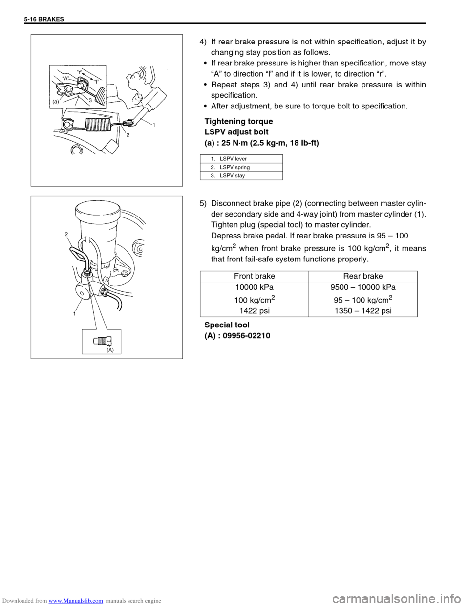
4) If rear brake pressure is not within specification, adjust it by
changing stay position as follows.
If rear brake pressure is higher than specification, move stay
“A” to direction “l” and if it is lower, to direction “r”.
Repeat steps 3) and 4) until rear brake pressure is within
specification.
After adjustment, be sure to torque bolt to specification.
Tightening torque
LSPV adjust bolt
(a) : 25 N·m (2.5 kg-m, 18 Ib-ft)
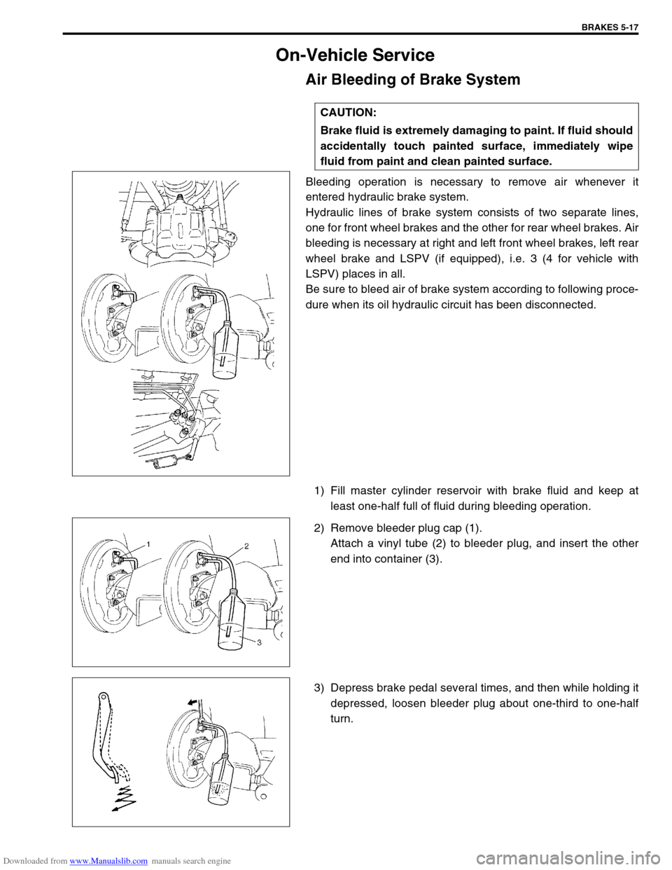
5) Disconnect brake pipe (2) (connecting between master cylin-
der secondary side and 4-way joint) from master cylinder (1).
Tighten plug (special tool) to master cylinder.
Depress brake pedal. If rear brake pressure is 95 – 100
kg/cm
2 when front brake pressure is 100 kg/cm2, it means
that front fail-safe system functions properly.
Special tool
(A) : 09956-02210
1. LSPV lever
2. LSPV spring
3. LSPV stay
Front brake Rear brake
10000 kPa
100 kg/cm
2
1422 psi9500 – 10000 kPa
95 – 100 kg/cm
2
1350 – 1422 psi
Page 278 of 687

Downloaded from www.Manualslib.com manuals search engine BRAKES 5-17
On-Vehicle Service
Air Bleeding of Brake System
Bleeding operation is necessary to remove air whenever it
entered hydraulic brake system.
Hydraulic lines of brake system consists of two separate lines,
one for front wheel brakes and the other for rear wheel brakes. Air
bleeding is necessary at right and left front wheel brakes, left rear
wheel brake and LSPV (if equipped), i.e. 3 (4 for vehicle with
LSPV) places in all.
Be sure to bleed air of brake system according to following proce-
dure when its oil hydraulic circuit has been disconnected.
1) Fill master cylinder reservoir with brake fluid and keep at
least one-half full of fluid during bleeding operation.
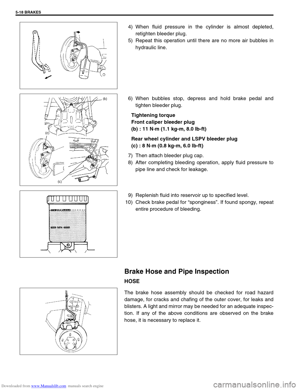
2) Remove bleeder plug cap (1).
Attach a vinyl tube (2) to bleeder plug, and insert the other
end into container (3).
3) Depress brake pedal several times, and then while holding it
depressed, loosen bleeder plug about one-third to one-half
turn. CAUTION:
Brake fluid is extremely damaging to paint. If fluid should
accidentally touch painted surface, immediately wipe
fluid from paint and clean painted surface.
Page 279 of 687

Downloaded from www.Manualslib.com manuals search engine 5-18 BRAKES
4) When fluid pressure in the cylinder is almost depleted,
retighten bleeder plug.
5) Repeat this operation until there are no more air bubbles in
hydraulic line.
6) When bubbles stop, depress and hold brake pedal and
tighten bleeder plug.
Tightening torque
Front caliper bleeder plug
(b) : 11 N·m (1.1 kg-m, 8.0 lb-ft)
Rear wheel cylinder and LSPV bleeder plug
(c) : 8 N·m (0.8 kg-m, 6.0 lb-ft)
7) Then attach bleeder plug cap.
8) After completing bleeding operation, apply fluid pressure to
pipe line and check for leakage.
9) Replenish fluid into reservoir up to specified level.
10) Check brake pedal for “sponginess”. If found spongy, repeat
entire procedure of bleeding.
Brake Hose and Pipe Inspection
HOSE
The brake hose assembly should be checked for road hazard
damage, for cracks and chafing of the outer cover, for leaks and
blisters. A light and mirror may be needed for an adequate inspec-
tion. If any of the above conditions are observed on the brake
hose, it is necessary to replace it.
Page 289 of 687
Downloaded from www.Manualslib.com manuals search engine 5-28 BRAKES
CHECK FOR FRONT BRAKE AFTER INSTALLATION
Mount tires and make certain that they rotate smoothly, with a
force of less than 3.0 kg (6.6 Ib).
If tire rotation is heavy, check the following:
Piston, piston seal and cylinder slide bush of caliper for
installation.
Wheel bearings for breakage.
Disc for flatness (Improper flatness brings disc into contact
with lining during rotation and makes rotation heavy).
To check this, measure disc deflection.NOTE:
For above check the following must be observed.
Jack up front wheels, both right and left, off the
ground.
Shift transfer shift lever to 2H (rear wheel) position (if
equipped) and start engine for a few seconds then
stop.
Side figure shows outer periphery of tire.
Be careful not to depress brake pedal when checking
tire for rotation.
1. String
2. Spring measure
Page 290 of 687
Downloaded from www.Manualslib.com manuals search engine BRAKES 5-29
Rear Brake
Brake drum
REMOVAL
1) Hoist vehicle and pull up parking brake lever.
2) Remove wheel.
3) Release parking brake lever.
4) Loosen parking brake cable adjusting nut (1).
1. Brake back plate 5. Shoe return spring lower 9. Shoe hold down pin
2. Brake shoe 6. Adjuster lever 10. Wheel cylinder
: Apply brake fluid to piston cap
3. Spring and rod assembly 7. Adjuster spring Tightening torque
4. Parking brake shoe lever 8. Shoe hold down spring
Page 295 of 687

Downloaded from www.Manualslib.com manuals search engine 5-34 BRAKES
INSTALLATION
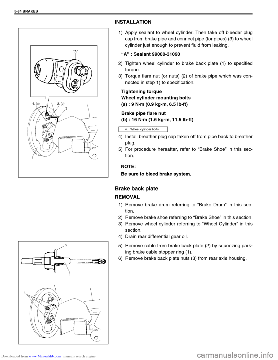
1) Apply sealant to wheel cylinder. Then take off bleeder plug
cap from brake pipe and connect pipe (for pipes) (3) to wheel
cylinder just enough to prevent fluid from leaking.
“A” : Sealant 99000-31090
2) Tighten wheel cylinder to brake back plate (1) to specified
torque.
3) Torque flare nut (or nuts) (2) of brake pipe which was con-
nected in step 1) to specification.
Tightening torque
Wheel cylinder mounting bolts
(a) : 9 N·m (0.9 kg-m, 6.5 lb-ft)
Brake pipe flare nut
(b) : 16 N·m (1.6 kg-m, 11.5 lb-ft)
4) Install breather plug cap taken off from pipe back to breather
plug.
5) For procedure hereafter, refer to “Brake Shoe” in this sec-
tion.
Brake back plate
REMOVAL
1) Remove brake drum referring to “Brake Drum” in this sec-
tion.
2) Remove brake shoe referring to “Brake Shoe” in this section.
3) Remove wheel cylinder referring to “Wheel Cylinder” in this
section.
4) Drain rear differential gear oil.
5) Remove cable from brake back plate (2) by squeezing park-
ing brake cable stopper ring (1).
6) Remove brake back plate nuts (3) from rear axle housing.
4. Wheel cylinder bolts
NOTE:
Be sure to bleed brake system.
Page 296 of 687
Downloaded from www.Manualslib.com manuals search engine BRAKES 5-35
7) Using special tools, draw out rear axle shaft with brake back
plate.
Special tool
(A) : 09943-35511
(B) : 09942-15510
8) Remove wheel bearing retainer and wheel sensor ring (if
equipped with ABS), refer to “Rear Axle Shaft and Wheel
Bearing” in Section 3E.
9) Remove brake back plate from axle shaft.
INSTALLATION
1) Install wheel cylinder, and tighten wheel cylinder bolts to
specified torque. Refer to “Wheel Cylinder” in this section.
2) Install brake back plate (2) to axle shaft (1).
3) For installation procedure here after perform “Rear Axle
Shaft and Wheel Bearing” in Section 3E.
3. Wheel bearing
4. Retainer ring
Page 309 of 687
Downloaded from www.Manualslib.com manuals search engine 5-48 BRAKES
Brake Hose/Pipe
Front brake hose/pipe
For left-hand steering vehicle
[A] : For vehicle without ABS X : View X 5. Brake caliper 12. To front left brake caliper
[B] : For vehicle with ABS Y : View Y 6. 4 way joint 13. To rear brake
F : Front side Z : View Z 7. 5 way joint a-d: Clamp
R : Right side 1. E-ring 8. ABS hydraulic unit/control mod-
ule assemblyTightening torque
T : Top side 2. Flexible hose 9. P valve
V : View V 3. Hose washer 10. Hose bracket
W : View W 4. Hose bolt 11. To front right brake caliper