Page 593 of 687

Downloaded from www.Manualslib.com manuals search engine 6B-16 ENGINE COOLING
INSPECTION
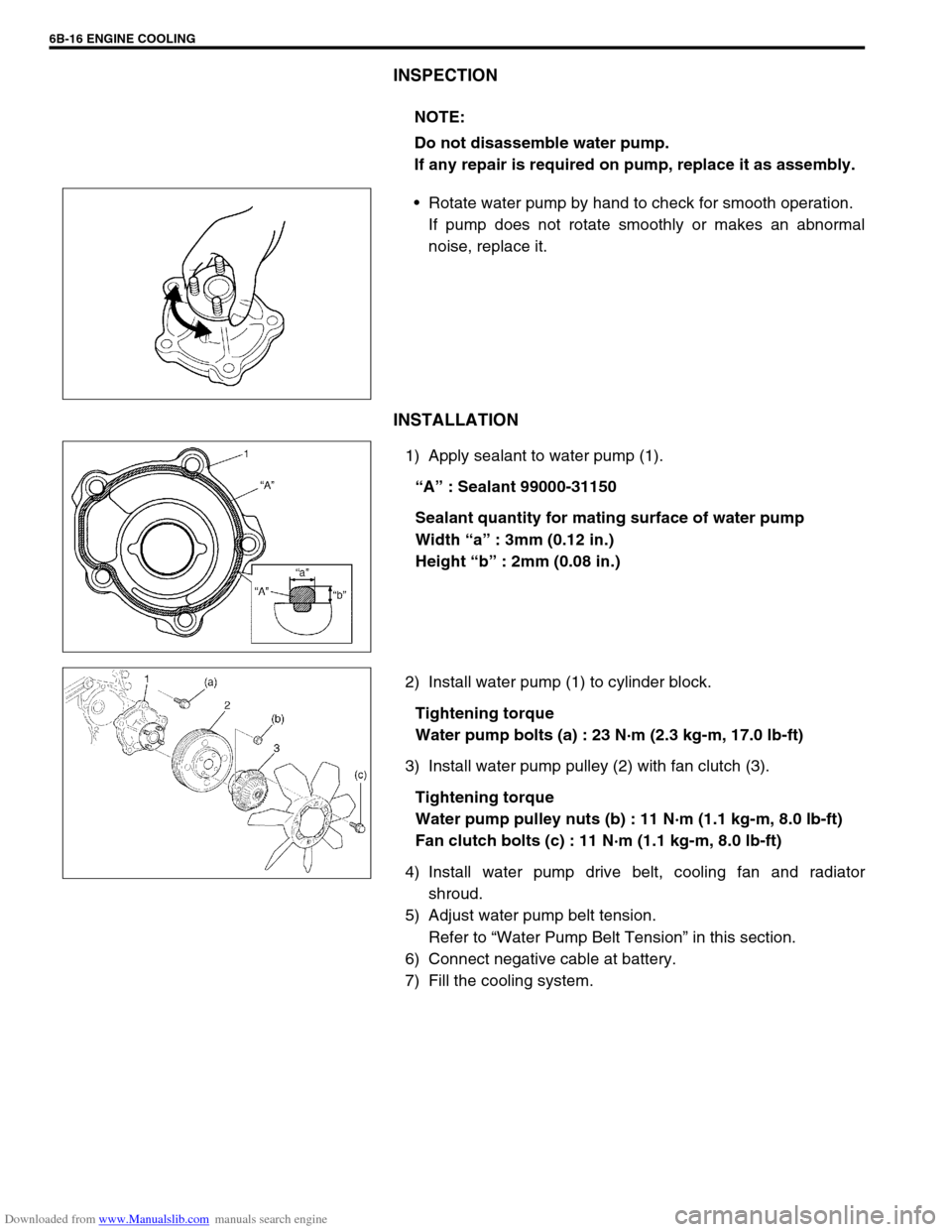
Rotate water pump by hand to check for smooth operation.
If pump does not rotate smoothly or makes an abnormal
noise, replace it.
INSTALLATION
1) Apply sealant to water pump (1).
“A” : Sealant 99000-31150
Sealant quantity for mating surface of water pump
Width “a” : 3mm (0.12 in.)
Height “b” : 2mm (0.08 in.)
2) Install water pump (1) to cylinder block.
Tightening torque
Water pump bolts (a) : 23 N·m (2.3 kg-m, 17.0 lb-ft)
3) Install water pump pulley (2) with fan clutch (3).
Tightening torque
Water pump pulley nuts (b) : 11 N·m (1.1 kg-m, 8.0 lb-ft)
Fan clutch bolts (c) : 11 N·m (1.1 kg-m, 8.0 lb-ft)
4) Install water pump drive belt, cooling fan and radiator
shroud.
5) Adjust water pump belt tension.
Refer to “Water Pump Belt Tension” in this section.
6) Connect negative cable at battery.
7) Fill the cooling system.NOTE:
Do not disassemble water pump.
If any repair is required on pump, replace it as assembly.
Page 594 of 687
Downloaded from www.Manualslib.com manuals search engine ENGINE COOLING 6B-17
Required Service Material
Tightening Torque Specification
MaterialRecommended SUZUKI product
(Part Number)Use
Ethylene glycol base
coolant (Anti-freeze /
Anti-corrosion coolant)–Additive to engine cooling system for improving
cooling efficiency and for protection against
rusting.
SealantSUZUKI BOND NO.1207C
(99000 – 31150)To apply to water pump mating surface.
Fastening partTightening torque
Nm kg-m lb-ft
Water pump bolt 23 2.3 17.0
Thermostat cap bolt 11 1.1 8.0
Thermostat case bolt 25 2.5 18.0
Fun clutch bolt 11 1.1 8.0
Page 597 of 687
Downloaded from www.Manualslib.com manuals search engine 6C-2 ENGINE FUEL
General Description
Fuel System
The main components of the fuel system are fuel tank, fuel pump assembly with fuel filter and fuel level gauge
and fuel cut valve, fuel feed line, fuel return line and fuel vapor line.
For the details of fuel flow and fuel vapor flow, refer to “Fuel Delivery System” and “Emission Control System” in
Section 6E.
Fuel Tank
The fuel tank is located under the rear section of the vehicle. The
fuel pump assembly is installed in fuel tank. Whenever servicing
the fuel pump assembly, the fuel tank must be removed from the
vehicle.
1. Fuel tank 4. Fuel filler cap 7. Fuel vapor line 10. Fuel filler hose clamp
2. Fuel pump assembly 5. Fuel feed line 8. Fuel filler neck Tightening torque
3. Breather hose 6. Fuel return line 9. Fuel tank mounting bolt
Page 600 of 687

Downloaded from www.Manualslib.com manuals search engine ENGINE FUEL 6C-5
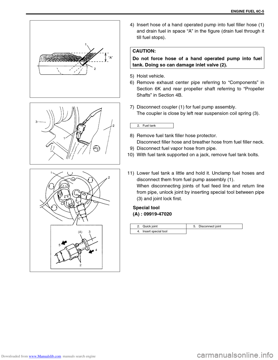
4) Insert hose of a hand operated pump into fuel filler hose (1)
and drain fuel in space “A” in the figure (drain fuel through it
till fuel stops).
5) Hoist vehicle.
6) Remove exhaust center pipe referring to “Components” in
Section 6K and rear propeller shaft referring to “Propeller
Shafts” in Section 4B.
7) Disconnect coupler (1) for fuel pump assembly.
The coupler is close by left rear suspension coil spring (3).
8) Remove fuel tank filler hose protector.
Disconnect filler hose and breather hose from fuel filler neck.
9) Disconnect fuel vapor hose from pipe.
10) With fuel tank supported on a jack, remove fuel tank bolts.
11) Lower fuel tank a little and hold it. Unclamp fuel hoses and
disconnect them from fuel pump assembly (1).
When disconnecting joints of fuel feed line and return line
from pipe, unlock joint by inserting special tool between pipe
(3) and joint lock first.
Special tool
(A) : 09919-47020 CAUTION:
Do not force hose of a hand operated pump into fuel
tank. Doing so can damage inlet valve (2).
2. Fuel tank
2. Quick joint 5. Disconnect joint
4. Insert special tool
Page 602 of 687

Downloaded from www.Manualslib.com manuals search engine ENGINE FUEL 6C-7
INSTALLATION
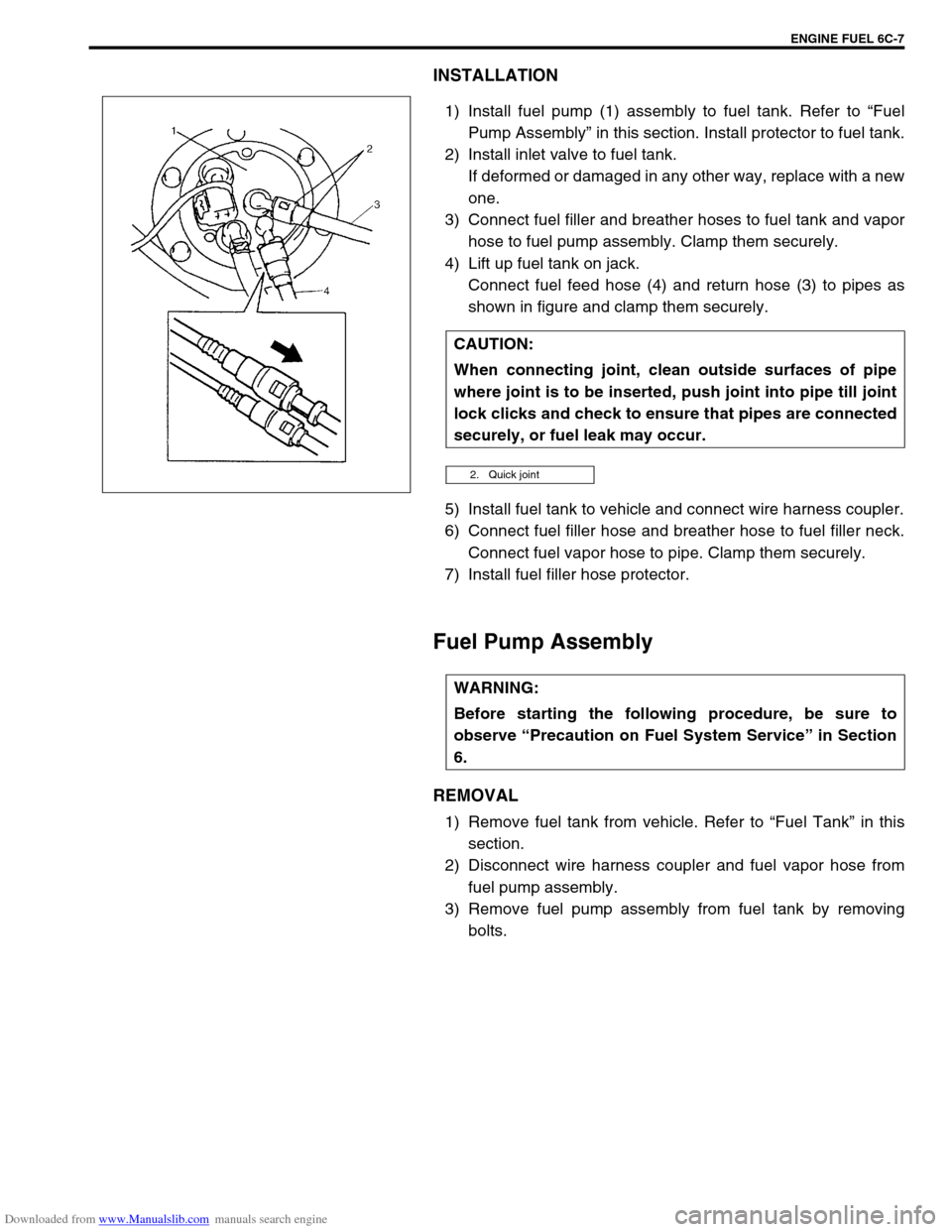
1) Install fuel pump (1) assembly to fuel tank. Refer to “Fuel
Pump Assembly” in this section. Install protector to fuel tank.
2) Install inlet valve to fuel tank.
If deformed or damaged in any other way, replace with a new
one.
3) Connect fuel filler and breather hoses to fuel tank and vapor
hose to fuel pump assembly. Clamp them securely.
4) Lift up fuel tank on jack.
Connect fuel feed hose (4) and return hose (3) to pipes as
shown in figure and clamp them securely.
5) Install fuel tank to vehicle and connect wire harness coupler.
6) Connect fuel filler hose and breather hose to fuel filler neck.
Connect fuel vapor hose to pipe. Clamp them securely.
7) Install fuel filler hose protector.
Fuel Pump Assembly
REMOVAL
1) Remove fuel tank from vehicle. Refer to “Fuel Tank” in this
section.
2) Disconnect wire harness coupler and fuel vapor hose from
fuel pump assembly.
3) Remove fuel pump assembly from fuel tank by removing
bolts. CAUTION:
When connecting joint, clean outside surfaces of pipe
where joint is to be inserted, push joint into pipe till joint
lock clicks and check to ensure that pipes are connected
securely, or fuel leak may occur.
2. Quick joint
WARNING:
Before starting the following procedure, be sure to
observe “Precaution on Fuel System Service” in Section
6.
Page 604 of 687

Downloaded from www.Manualslib.com manuals search engine ENGINE FUEL 6C-9
INSTALLATION
1) Clean mating surfaces of fuel pump assembly and fuel tank.
2) Install new gasket (2) and plate (3) to fuel pump assembly
(1) then install fuel pump assembly to fuel tank.
Tightening torque
Fuel pump assembly bolts (a) : 10 N·m (1.0 kg-m, 7.5 lb-ft)
3) Connect wire harness coupler (2) and fuel vapor hose (3) to
fuel pump assembly (1).
4) Install fuel tank to vehicle. Refer to “Fuel Tank” in this sec-
tion. CAUTION:
While removing fuel level gauge, do not contact resis-
tor plate (2) or deform arm (3). It may cause fuel level
gauge to fail.
When removing grommet from fuel tube or bracket sub
assembly, be very careful not to cause damage to
grommet installed section (sealed section in bore).
Should it be damaged, replace it with new one, or fuel
will leak from that part.
NOTE:
When removing fuel level gauge, press snap-fit part (1)
and slide it in the arrow direction as shown in figure.
When installing fuel level gauge to housing, fit protru-
sion (4) of fuel level gauge in groove (5) in housing and
slide it up till lug (6) fits in window (7) securely. Refer to
figure shown.
[A] : Removal
[B] : Installation
Page 605 of 687
Downloaded from www.Manualslib.com manuals search engine 6C-10 ENGINE FUEL
Tightening Torque Specification
Special Tool
Fastening partTightening torque
Nm kg-m lb-ft
Fuel pump assembly bolt 10 1.0 7.5
09919-47020
Quick joint remover
Page 620 of 687

Downloaded from www.Manualslib.com manuals search engine ENGINE AND EMISSION CONTROL SYSTEM 6E-15
On-Vehicle Service
Accelerator cable adjustment
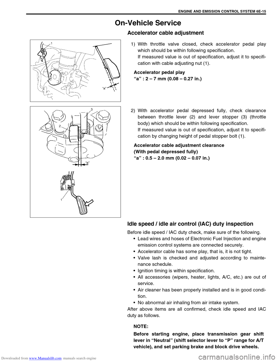
1) With throttle valve closed, check accelerator pedal play
which should be within following specification.
If measured value is out of specification, adjust it to specifi-
cation with cable adjusting nut (1).
Accelerator pedal play
“a” : 2 – 7 mm (0.08 – 0.27 in.)
2) With accelerator pedal depressed fully, check clearance
between throttle lever (2) and lever stopper (3) (throttle
body) which should be within following specification.
If measured value is out of specification, adjust it to specifi-
cation by changing height of pedal stopper bolt (1).
Accelerator cable adjustment clearance
(With pedal depressed fully)
“a” : 0.5 – 2.0 mm (0.02 – 0.07 in.)
Idle speed / idle air control (IAC) duty inspection
Before idle speed / IAC duty check, make sure of the following.
Lead wires and hoses of Electronic Fuel Injection and engine
emission control systems are connected securely.
Accelerator cable has some play, that is, it is not tight.
Valve lash is checked and adjusted according to mainte-
nance schedule.
Ignition timing is within specification.
All accessories (wipers, heater, lights, A/C, etc.) are out of
service.
Air cleaner has been properly installed and is in good condi-
tion.
No abnormal air inhaling from air intake system.
After above items are all confirmed, check idle speed and IAC
duty as follows.
NOTE:
Before starting engine, place transmission gear shift
lever in “Neutral” (shift selector lever to “P” range for A/T
vehicle), and set parking brake and block drive wheels.