Page 657 of 687

Downloaded from www.Manualslib.com manuals search engine 6F-8 IGNITION SYSTEM (ELECTRONIC IGNITION SYSTEM)
6) Measure resistance between terminals as follows by using
analog type ohmmeter.
If check result is not satisfactory, replace ignition coil assem-
bly.
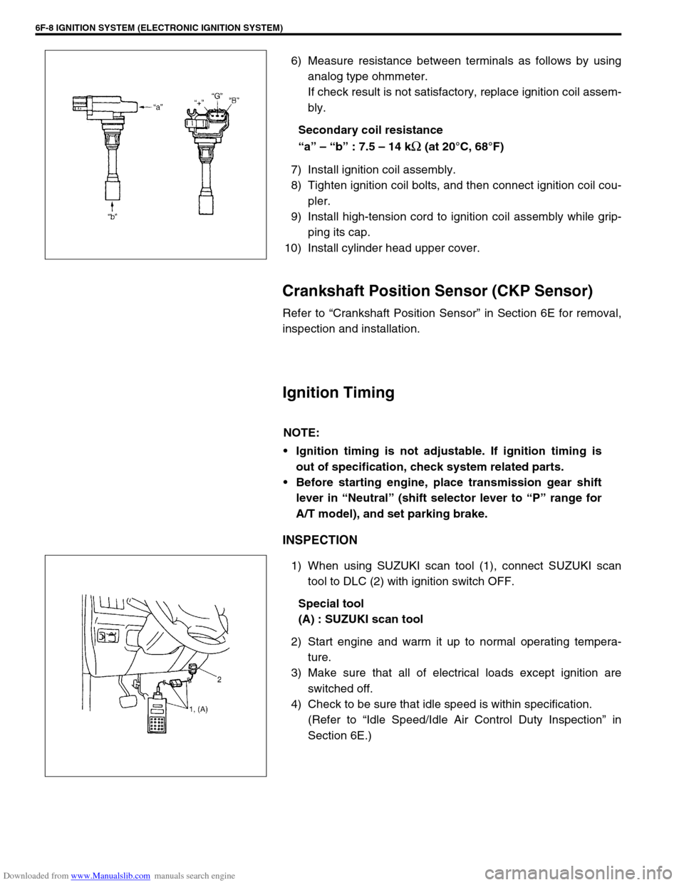
Secondary coil resistance
“a” – “b” : 7.5 – 14 k
Ω (at 20°C, 68°F)
7) Install ignition coil assembly.
8) Tighten ignition coil bolts, and then connect ignition coil cou-
pler.
9) Install high-tension cord to ignition coil assembly while grip-
ping its cap.
10) Install cylinder head upper cover.
Crankshaft Position Sensor (CKP Sensor)
Refer to “Crankshaft Position Sensor” in Section 6E for removal,
inspection and installation.
Ignition Timing
INSPECTION
1) When using SUZUKI scan tool (1), connect SUZUKI scan
tool to DLC (2) with ignition switch OFF.
Special tool
(A) : SUZUKI scan tool
2) Start engine and warm it up to normal operating tempera-
ture.
3) Make sure that all of electrical loads except ignition are
switched off.
4) Check to be sure that idle speed is within specification.
(Refer to “Idle Speed/Idle Air Control Duty Inspection” in
Section 6E.)
NOTE:
Ignition timing is not adjustable. If ignition timing is
out of specification, check system related parts.
Before starting engine, place transmission gear shift
lever in “Neutral” (shift selector lever to “P” range for
A/T model), and set parking brake.
Page 664 of 687
Downloaded from www.Manualslib.com manuals search engine CRANKING SYSTEM 6G-5
NO-LOAD PERFORMANCE TEST
Connect battery and ammeter to starter as shown.
Check that starter rotates smoothly and steadily with pinion mov-
ing out. Check that ammeter indicates specified current.
Specified current (No-load performance test)
: 90 A MAX. at 11 V
On-Vehicle Service
Starting Motor
DISMOUNTING
1) Disconnect negative (–) battery lead at battery.
2) Disconnect magnetic switch lead wire (6) and battery cable (7) from starting motor terminals.
3) Remove starting motor mount bolts (4) and nut (5).
4) Remove starting motor (1).
REMOUNTING
Reverse the dismounting procedure.
1. Starting motor 3. Transmission case 5. Starting motor mounting nut 7. Battery cable
2. Clutch housing upper plate 4. Starting motor mounting bolt 6. Magnetic switch lead wire Tightening Torque
Page 669 of 687

Downloaded from www.Manualslib.com manuals search engine 6H-2 CHARGING SYSTEM
General Description
Battery
The battery has three major functions in the electrical system.
It is a source of electrical energy for cranking the engine.
It acts as a voltage stabilizer for the electrical system.
It can, for a limited time, provide energy when the electrical
load exceeds the output of the generator.
CARRIER AND HOLD-DOWN
The battery carrier should be in good condition so that it will sup-
port the battery securely and keep it level.
Before installing the battery, the battery carrier and hold-down
clamp should be clean and free from corrosion and make certain
there are no parts in carrier.
To prevent the battery from shaking in its carrier, the hold-down
bolts should be tight enough but not over-tightened.
ELECTROLYTE FREEZING
The freezing point of electrolyte depends on its specific gravity.
Since freezing may ruin a battery, it should be protected against
freezing by keeping it in a fully charged condition. If a battery is
frozen accidentally, it should not be charged until it is warmed.
SULFATION
If the battery is allowed to stand for a long period in discharged
condition, the lead sulfate becomes converted into a hard, crystal-
line substance, which will not easily turn back to the active mate-
rial again during the subsequent recharging. “Sulfation” means
the result as well as the process of that reaction.
Such a battery can be revived by very slow charging and may be
restored to usable condition but its capacity is lower than before.
Page 674 of 687

Downloaded from www.Manualslib.com manuals search engine CHARGING SYSTEM 6H-7
How to use the temperature-corrected state-of-charge
graph
Suppose your S.G. reading is 1.28 and the battery temperature is
–5 °C (23 °F). Locate the intersection of the –5 °C line and the
1.28 S.G. line.
The intersection is within the “A” zone (shaded area in the graph)
and that means CHARGED STATE.
To know how much the battery is charged, draw a line parallel to
the zone demarcation line and extend it to the right till it meets
with the percentage scale. In the present example, the line meets
at about 85% point on the percentage scale. Therefore, the bat-
tery is charged up to the 85% level.
Generator
Trouble in charging system will show up as one or more of follow-
ing conditions:
1) Faulty indicator lamp operation.
2) An undercharged battery as evidenced by slow cranking or
indicator dark.
3) An overcharged battery as evidenced by excessive spewing
of electrolyte from vents.
Noise from generator may be caused by a loose drive pulley,
loose mounting bolts, worn or dirty bearings, defective diode, or
defective stator.
FAULTY INDICATOR LAMP OPERATION
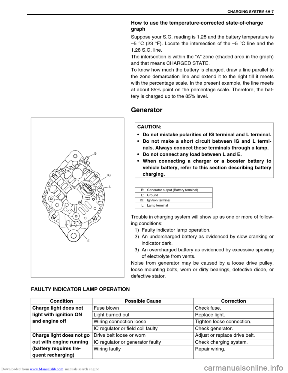
CAUTION:
Do not mistake polarities of IG terminal and L terminal.
Do not make a short circuit between IG and L termi-
nals. Always connect these terminals through a lamp.
Do not connect any load between L and E.
When connecting a charger or a booster battery to
vehicle battery, refer to this section describing battery
charging.
B: Generator output (Battery terminal)
E: Ground
IG: Ignition terminal
L: Lamp terminal
Condition Possible Cause Correction
Charge light does not
light with ignition ON
and engine offFuse blown Check fuse.
Light burned out Replace light.
Wiring connection loose Tighten loose connection.
IC regulator or field coil faulty Check generator.
Charge light does not go
out with engine running
(battery requires fre-
quent recharging)Drive belt loose or worn Adjust or replace drive belt.
IC regulator or generator faulty Check charging system.
Wiring faulty Repair wiring.
Page 678 of 687
Downloaded from www.Manualslib.com manuals search engine CHARGING SYSTEM 6H-11
Dismounting
1) Disconnect negative cable (3).
2) Disconnect positive cable (2).
3) Remove retainer (5).
4) Remove battery (1).
Handling
When handling battery, following safety precautions should be
followed:
Hydrogen gas is produced by battery. A flame or spark near
battery may cause the gas to ignite.
Battery fluid is highly acidic. Avoid spilling on clothing or
other fabric. Any spilled electrolyte should be flushed with
large quantity of water and cleaned immediately.
Remounting
1) Reverse removal procedure.
2) Torque battery cables to specification.
Tightening torque
Body ground bolt (a) : 8.0 N·m (0.8 kg-m, 6.0 lb-ft)
Generator
Generator belt
Refer to “Water Pump Belt and Cooling Fan” in Section 6B.
4. Body ground bolt
NOTE:
Check to be sure that ground cable has enough clear-
ance to hood panel by terminal.
Page 679 of 687
Downloaded from www.Manualslib.com manuals search engine 6H-12 CHARGING SYSTEM
Unit Repair Overhaul
Generator
Dismounting
1) Disconnect negative (–) cable (2) at battery (1).
2) Remove bolts (2) and then canister (1) together with its
bracket.
3) Disconnect “B” terminal wire (3) and coupler (2) from gener-
ator (1).
4) Remove generator belt. Refer to “Water Pump Belt and
Cooling Fan” in Section 6B.
5) Remove generator.
1. Generator adjusting bolt
2. Generator pivot bolt
3.“B” terminal
Page 680 of 687
Downloaded from www.Manualslib.com manuals search engine CHARGING SYSTEM 6H-13
Remounting
1) Mount generator on the generator bracket.
2) Tighten generator bolts.
Tightening torque
Generator pivot bolt
(a) : 23 N·m (2.3 kg-m, 16.5 lb-ft)
(b) : 50 N·m (5.0 kg-m, 36.0 lb-ft)
3) Install generator (cooling fan) belt. Refer to “Water Pump
Belt and Cooling Fan” in Section 6B.
4) Connect “B” terminal wire (3) and coupler to generator.
Tightening torque
“B” terminal outer nut of generator
(b) : 8.0 N·m (0.8 kg-m, 6.0 lb-ft)
5) Install canister.
6) Connect negative (–) cable at battery.
Disassembly and reassembly
1. Upper generator bolt (Short)
2. Lower generator bolt (Long)
1. Pulley 5. Rotor 9. Rear housing
2. Front housing 6. Stator 10. Brush
3. Bearing 7. IC regulator
4. Retainer 8. Rectifier
Page 684 of 687

Downloaded from www.Manualslib.com manuals search engine CHARGING SYSTEM 6H-17
Specifications
Battery
55B24R TYPE
38B20R TYPE
Generator
Tightening Torque Specification
Rated capacity 36 AH/5HR, 12 Volts
Electrolyte 3.1 L (6.55/5.46 US/lmp pt)
Electrolyte S.G. 1.28 when fully charged at 20 °C (68 °F)
Rated capacity 28 AH/5HR, 12 Volts
Electrolyte 2.1 L (4.44/3.70 US/lmp pt)
Electrolyte S.G. 1.28 when fully charged at 20 °C (68 °F)
Type 70 A type
Rated voltage 12 V
Nominal output 70 A
Permissible max. speed 18,000 r/min.
No-load speed 1,300 r/min (rpm)
Setting voltage 14.4 to 15.0 V
Permissible ambient temperature–30 to 90 °C (–22 to 194 °F)
Polarity Negative ground
Rotation Clockwise viewed from pulley side
Fastening partTightening torque
Nm kg-m lb-ft
Body ground bolt 8 0.8 6.0
Generator mounting bolts 23 2.3 16.5
“B” terminal inner nut 4.2 0.42 3.0
“B” terminal outer nut 8 0.8 6.0
Pulley nut 118 11.8 85.5
Rear end frame nuts
4.50.453.5
Rear end cover nuts
Rectifier “B” bolt 3.9 0.39 3.0
Stator stud bolts 8.8 0.88 6.5
Drive end bearing plate screws 2.6 0.26 2.0
Rectifier screws
2.00.201.5
Regulator and brush holder screws
Terminal plate bolt 3.8 0.38 3.0