Page 630 of 687

Downloaded from www.Manualslib.com manuals search engine ENGINE AND EMISSION CONTROL SYSTEM 6E-25
INSTALLATION
For installation, reverse removal procedure and note following
precautions.
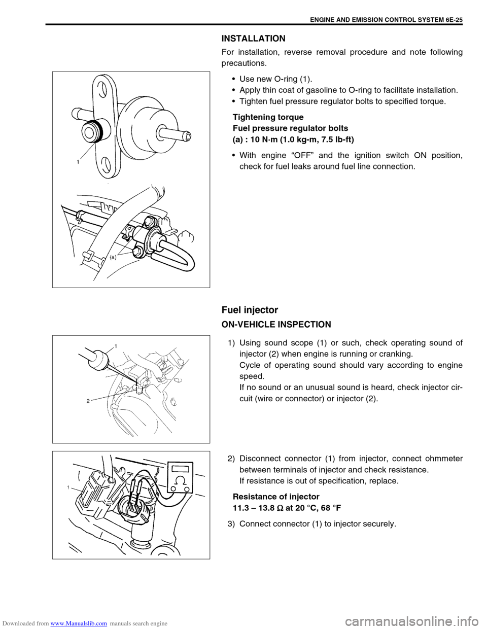
Use new O-ring (1).
Apply thin coat of gasoline to O-ring to facilitate installation.
Tighten fuel pressure regulator bolts to specified torque.
Tightening torque
Fuel pressure regulator bolts
(a) : 10 N·m (1.0 kg-m, 7.5 lb-ft)
With engine “OFF” and the ignition switch ON position,
check for fuel leaks around fuel line connection.
Fuel injector
ON-VEHICLE INSPECTION
1) Using sound scope (1) or such, check operating sound of
injector (2) when engine is running or cranking.
Cycle of operating sound should vary according to engine
speed.
If no sound or an unusual sound is heard, check injector cir-
cuit (wire or connector) or injector (2).
2) Disconnect connector (1) from injector, connect ohmmeter
between terminals of injector and check resistance.
If resistance is out of specification, replace.
Resistance of injector
11.3 – 13.8
Ω
ΩΩ Ω at 20 °C, 68 °F
3) Connect connector (1) to injector securely.
Page 631 of 687

Downloaded from www.Manualslib.com manuals search engine 6E-26 ENGINE AND EMISSION CONTROL SYSTEM
REMOVAL
1) Relieve fuel pressure according to procedure described in
“Fuel Pressure Relief Procedure” in Section 6.
2) Disconnect battery negative cable at battery.
3) Disconnect fuel injector couplers and release wire harness
from clamps.
4) Remove clamp bolt for fuel feed pipe and return pipe.
5) Remove fuel delivery pipe bolts (2).
6) Remove fuel injector(s) (3).
INSPECTION
1) Install injector (3) and fuel pressure regulator (4) to special
tool (injector checking tool).
Special tool
(A) : 09912-58421
2) Connect special tools (hose and attachment) to fuel feed
hose (1) of vehicle.
Special tool
(B) : 09912-58432
3) Connect special tool (test lead) to injector.
Special tool
(C) : 09930-88530
4) Install suitable vinyl tube onto injector nozzle to prevent fuel
from splashing out when injecting. CAUTION:
A small amount of fuel may come out after removal of
fuel injectors, cover them with shop cloth.
WARNING:
As fuel is injected in this inspection, perform in a well
ventilated area and away from open flames.
Use special care to prevent sparking when connecting
and disconnecting test lead to and from battery.
2. Fuel return line
Page 633 of 687
Downloaded from www.Manualslib.com manuals search engine 6E-28 ENGINE AND EMISSION CONTROL SYSTEM
INSTALLATION
For installation, reverse removal procedure and note following
precautions.
Replace injector O-ring (1) with new one using care not to
damage it.
Check if cushion (2) is scored or damaged. If it is, replace
with new one.
Apply thin coat of fuel to O-rings (1) and then install injectors
(3) into delivery pipe (4) and intake manifold.
Make sure that injectors (3) rotate smoothly (6). If not, proba-
ble cause is incorrect installation of O-ring (1). Replace O-
ring (1) with new one.
Tighten delivery pipe bolts (5) and make sure that injectors
(3) rotate smoothly (6).
After installation, with engine “OFF” and ignition switch “ON”,
check for fuel leaks around fuel line connection.
Page 639 of 687

Downloaded from www.Manualslib.com manuals search engine 6E-34 ENGINE AND EMISSION CONTROL SYSTEM
1) Disconnect negative cable at battery.
2) For sensor-1, remove exhaust manifold cover (1) and dis-
connect connector of heated oxygen sensor and release its
wire harness from clamps.
3) For sensor-2, disconnect connector of heated oxygen sensor
and release its wire harness from clamp. Hoist vehicle and
then remove exhaust No.1 pipe covers (3).
4) Remove heated oxygen sensor (2) from exhaust manifold or
exhaust No.1 pipe.
INSTALLATION
Reverse removal procedure noting the following.
Tighten heated oxygen sensor (2) to specified torque.
Tightening torque
Heated oxygen sensor (a) : 45 N·m (4.5 kg-m, 32.5 lb-ft)
Connect connector of heated oxygen sensor (2) and clamp
wire harness securely.
After installing heated oxygen sensor (2), start engine and
check that no exhaust gas leakage exists.
Camshaft position sensor
INSPECTION
Check camshaft position sensor referring to “DTC P0340 (No. 15)
Diag. Flow Table” in Section 6. If malfunction is found, replace.
REMOVAL
1) Disconnect negative cable at battery.
2) Disconnect connector from camshaft position sensor.
3) Remove camshaft position sensor from cylinder head.
INSTALLATION
1) Check that O-ring is free from damage.
2) Check that camshaft position sensor and signal rotor tooth
are free from any metal particles and damage.
3) Install camshaft position sensor to sensor case.
Tightening torque
Camshaft position sensor bolt
(a) : 10 N·m (1.0 kg-m, 7.5 lb-ft)
4) Connect connector to it securely.
5) Connect negative cable to battery.
[A] : HO2S-1
[B] : HO2S-2
Page 640 of 687
Downloaded from www.Manualslib.com manuals search engine ENGINE AND EMISSION CONTROL SYSTEM 6E-35
Crankshaft position sensor
INSPECTION
Check crankshaft position sensor referring to step 2 and 6 of
“DTC P0335 (No.23) Flow Table” in Section 6. If malfunction is
found, replace.
REMOVAL
1) Disconnect negative cable at battery.
2) Remove generator drive belt, loosen pivot bolt and move
generator outward.
3) Disconnect connector from crankshaft position sensor.
4) Remove crankshaft position sensor (1) from cylinder block.
INSTALLATION
1) Check to make sure that crankshaft position sensor and pul-
ley tooth is free from any metal particles and damage.
2) Install crankshaft position sensor to cylinder block.
3) Connect connector to it securely.
4) Adjust generator belt tension, refer to “Water Pump Belt Ten-
sion” in Section 6B.
5) Connect negative cable to battery.
Page 648 of 687

Downloaded from www.Manualslib.com manuals search engine ENGINE AND EMISSION CONTROL SYSTEM 6E-43
Tightening Torque Specifications
09931-76030
16/14 pin DLC cable Tech 2 kit (SUZUKI scan
tool) (See NOTE “C”.)
NOTE:
“A”: This kit includes the following items.
1. Tool body & washer, 2. Body plug, 3. Body attachment-1, 4. Holder, 5. Return hose & clamp,
6. Body attachment-2 & washer, 7. Hose attachment-1, 8. Hose attachment-2
“B”: This kit includes the following items and substitutes for the Tech 2 kit.
1. Storage case, 2. Operator’s manual, 3. Tech 1A, 4. DLC cable (14/26 pin, 09931-76040),
5. Test lead / probe, 6. Power source cable, 7. DLC cable adaptor, 8. Self-test adaptor
“C”: This kit includes the following items and substitutes for the Tech 1A kit.
1. Tech 2, 2. PCMCIA card, 3. DLC cable, 4. SAE 16/19 adapter, 5. Cigarette cable,
6. DLC loopback adapter, 7. Battery power cable, 8. RS232 cable, 9. RS232 adapter,
10. RS232 loopback connector, 11. Storage case, 12. Power supply
Fastening partTightening torque
Nm kg-m lb-ft
TP sensor mounting screw 2.5 0.25 1.8
IAC valve screw 3.5 0.35 2.5
ECT sensor 15 1.5 11.5
Heated oxygen sensor-1 and -2 45 4.5 32.5
Camshaft position sensor 10 1.0 7.5
Fuel pressure regulator bolt 10 1.0 7.5
Page 653 of 687

Downloaded from www.Manualslib.com manuals search engine 6F-4 IGNITION SYSTEM (ELECTRONIC IGNITION SYSTEM)
IGNITION SYSTEM DIAGNOSTIC FLOW TABLE
Step Action Yes No
1Was “Engine Diagnostic Flow Table” in Section 6 per-
formed?Go to Step 2. Go to “Engine Diag.
Flow Table” in Section
6.
2Ignition Spark Test
1) Check all spark plugs for condition and type refer-
ring to “Spark Plugs” section.
2) If OK, perform ignition spark test, referring to “Igni-
tion Spark Test” section.
Is spark emitted from all spark plugs?Go to Step 11. Go to Step 3.
3Diagnostic Trouble Code (DTC) Check
Is DTC stored in ECM?Go to applicable DTC
Diag. Flow Table in
Section 6.Go to Step 4.
4Electrical Connection Check
1) Check ignition coil assemblies and high-tension
cords for electrical connection.
Are they connected securely?Go to Step 5. Connect securely.
5High-tension Cords Check
1) Check high-tension cord for resistance referring to
“High-Tension Cords” section.
Is check result satisfactory?Go to Step 6. Replace high-tension
cord(s).
6Ignition Coil Assembly Power Supply and Ground Cir-
cuit Check
1) Check ignition coil assembly power supply and
ground circuits for open and short.
Are circuits in good condition?Go to Step 7. Repair or replace.
7Ignition Coil Assembly Check
1) Check ignition coil for resistance referring to “Igni-
tion Coil Assembly” section.
Is check result satisfactory?Go to Step 8. Replace ignition coil
assembly.
8Crankshaft Position (CKP) Sensor Check
1) Check crankshaft position sensor referring to Step
2 and 6 of “DTC P0335 (No.23) CKP Sensor Cir-
cuit Malfunction” in Section 6.
Is check result satisfactory?Go to Step 9. Tighten CKP sensor
bolt, replace CKP sen-
sor or CKP sensor
plate.
9Ignition Trigger Signal Circuit Check
1) Check ignition trigger signal wire for open, short
and poor connection.
Is circuit in good condition?Go to Step 10. Repair or replace.
10A Known-good Ignition Coil Assembly Substitution
1) Substitute a known-good ignition coil assembly
and then repeat Step 2.
Is check result of Step 2 satisfactory?Go to Step 11. Substitute a known-
good ECM and then
repeat Step 2.
11Ignition Timing Check
1) Check initial ignition timing and ignition timing
advance referring to “Ignition Timing” section.
Is check result satisfactory?System is in good con-
dition.Check CKP sensor,
CKP sensor plate and
input signals related to
this system.
Page 656 of 687

Downloaded from www.Manualslib.com manuals search engine IGNITION SYSTEM (ELECTRONIC IGNITION SYSTEM 6F-7
4) If any abnormality is found, adjust air gap, clean with spark
plug cleaner or replace them with specified new plugs.
For iridium/platinum spark plugs, replace them with new
plugs.
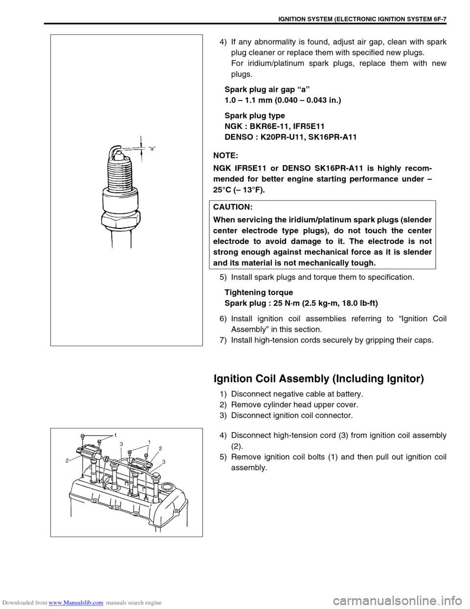
Spark plug air gap “a”
1.0 – 1.1 mm (0.040 – 0.043 in.)
Spark plug type
NGK : BKR6E-11, IFR5E11
DENSO : K20PR-U11, SK16PR-A11
5) Install spark plugs and torque them to specification.
Tightening torque
Spark plug : 25 N·m (2.5 kg-m, 18.0 lb-ft)
6) Install ignition coil assemblies referring to “Ignition Coil
Assembly” in this section.
7) Install high-tension cords securely by gripping their caps.
Ignition Coil Assembly (Including Ignitor)
1) Disconnect negative cable at battery.
2) Remove cylinder head upper cover.
3) Disconnect ignition coil connector.
4) Disconnect high-tension cord (3) from ignition coil assembly
(2).
5) Remove ignition coil bolts (1) and then pull out ignition coil
assembly. NOTE:
NGK IFR5E11 or DENSO SK16PR-A11 is highly recom-
mended for better engine starting performance under –
25°C (– 13°F).
CAUTION:
When servicing the iridium/platinum spark plugs (slender
center electrode type plugs), do not touch the center
electrode to avoid damage to it. The electrode is not
strong enough against mechanical force as it is slender
and its material is not mechanically tough.