Page 395 of 687

Downloaded from www.Manualslib.com manuals search engine 6-38 ENGINE GENERAL INFORMATION AND DIAGNOSIS
For TYPE A (See NOTE)
E189 Ignition switch 10 – 14 V Ignition switch ON
10 Main relay10 – 14 V Ignition switch OFF
0.4 – 1.5 V Ignition switch ON
11 Ignition switch 10 – 14 V Ignition switch ON
12 Rear defogger switch (if equipped)10 – 14 VIgnition switch ON and rear defogger
switch ON
0 – 1.3 VIgnition switch ON and rear defogger
switch OFF
13–– –
14Diag. Switch terminal (without
immobilizer indicator lamp)4 – 5 V Ignition switch ON
15Test switch terminal (without immo-
bilizer indicator lamp)4 – 5 V Ignition switch ON
16 A/C (input) signal10 – 14 VIgnition switch ON
A/C switch OFF
0 – 2 VIgnition switch ON
A/C switch ON
17 Lighting switch10 – 14 V Lighting switch ON
0 – 1.3 V Lighting switch OFF
18A/C condenser fan motor relay
(if equipped)0 – 1.0 V A/C is operating
10 – 14 V A/C is not operating
19 Fuel pump relay0 – 1 V For 2 seconds after ignition switch ON
10 – 14 V After the above time
20 Engine start signal 6 – 14 V While engine cranking
21 Stop lamp switch0 VIgnition switch ON
Stop lamp switch OFF
10 – 14 VIgnition switch ON
Stop lamp switch ON
22 Vehicle speed sensordeflect
between
0 – 1.6 and
4 – 14 VIgnition switch ON and rear right wheel
turned slowly with rear left wheel locked
23–– –
24–– – TERMINAL
NO.CIRCUIT NORMAL
VOLTAGECONDITION
NOTE:
See NOTE in “ECM TERMINAL VOLTAGE VALUES TABLE” for applicable model.
TERMINAL
NO.CIRCUIT NORMAL
VOLTAGECONDITION
E171–– –
2 R-range signal (A/T)10 – 14 VIgnition switch ON and shift select switch
in R range
0 – 1.3 VIgnition switch ON and shift select switch
in other than R range
3 Blank––
Page 396 of 687

Downloaded from www.Manualslib.com manuals search engine ENGINE GENERAL INFORMATION AND DIAGNOSIS 6-39
For TYPE B (See NOTE)
E174Blank––
5 Overdrive cut signal (A/T)0 – 1.0 VIgnition switch ON and ECT less than
60 °C
10 – 14 VIgnition switch ON and ECT more than
60 °C
6 D-range idle up signal (A/T)10 – 14 VIgnition switch ON and shift select switch
in other than P and N range
0 – 1.6 VIgnition switch ON and shift select switch
in P and N range
7 Stop lamp switch0 VIgnition switch ON
Stop lamp switch OFF
10 – 14 VIgnition switch ON
Stop lamp switch ON
8–– –
9 Ignition switch 10 – 14 V Ignition switch ON
10–– –
11 Vehicle speed sensordeflect
between
0 – 1.6 and
4 – 14 VIgnition switch ON and rear right wheel
turned slowly with rear left wheel locked
12 ABS signal (if equipped) 10 – 14 V Ignition switch ON
13 Engine start signal 6 – 14 V While engine cranking
14–– –
15–– –
16 Rear defogger switch (if equipped)10 – 14 V Ignition switch ON and rear defogger
switch ON
0 – 1.3 V Ignition switch ON and rear defogger
switch OFF
17 A/T failure signal (with immobilizer
indicator lamp) (A/T)–– TERMINAL
NO.CIRCUIT NORMAL
VOLTAGECONDITION
NOTE:
See NOTE in “ECM TERMINAL VOLTAGE VALUES TABLE” for applicable model.
TERMINAL
NO.CIRCUIT NORMAL
VOLTAGECONDITION
E171 A/C evaporator temp. sensor 2.0 – 2.3 VIgnition switch ON
A/C evaporator temp. sensor at 25 °C
(77 °F)
2 R-range signal (A/T)10 – 14 VIgnition switch ON and shift select switch
in R range
0 – 1.3 VIgnition switch ON and shift select switch
in other than R range
3Blank––
4Blank––
Page 454 of 687
![SUZUKI JIMNY 2005 3.G Service Workshop Manual Downloaded from www.Manualslib.com manuals search engine ENGINE GENERAL INFORMATION AND DIAGNOSIS 6-97
[A] Fig. 1 for Step 3 / [B] Fig. 2 for Step 43 Check Idle Air Control System.
1) Connect SUZUKI s SUZUKI JIMNY 2005 3.G Service Workshop Manual Downloaded from www.Manualslib.com manuals search engine ENGINE GENERAL INFORMATION AND DIAGNOSIS 6-97
[A] Fig. 1 for Step 3 / [B] Fig. 2 for Step 43 Check Idle Air Control System.
1) Connect SUZUKI s](/manual-img/20/7588/w960_7588-453.png)
Downloaded from www.Manualslib.com manuals search engine ENGINE GENERAL INFORMATION AND DIAGNOSIS 6-97
[A] Fig. 1 for Step 3 / [B] Fig. 2 for Step 43 Check Idle Air Control System.
1) Connect SUZUKI scan tool to DLC with igni-
tion switch OFF, set parking brake and block
drive wheels. See Fig. 1.
2) Warm up engine to normal operating tem-
perature.
3) Clear DTC and select “MISC TEST” mode
on SUZUKI scan tool.
Is it possible to control (increase and reduce)
engine idle speed by using SUZUKI scan tool? Intermittent trouble or
faulty ECM.
Check for intermittent
referring to “Intermittent
and Poor Connection” in
Section 0A.Go to Step 5.
4 Check Idle Air Control System.
1) Remove IAC valve from throttle boy refer-
ring to “IAC Valve” in Section 6E.
2) Check IAC valve for operation referring to
“IAC Valve” in Section 6E. See Fig. 2.
Is check result satisfactory?Intermittent trouble or
faulty ECM.
Check for intermittent
referring to “Intermittent
and Poor Connection” in
Section 0A.Go to Step 5.
5 Check Wire Harness for Open and Short.
1) Turn ignition switch OFF.
2) Disconnect IAC valve connector.
3) Check for proper connection to IAC valve at
each terminals.
4) If OK, disconnect ECM connector.
5) Check for proper connection to ECM at
E19-6 terminal.
6) If OK, check “Bl/B”, “G/Y” and “B/R” circuit
for open and short.
Are they in good condition?Replace IAC valve and
recheck.Repair or replace. Step Action Yes No
Page 485 of 687
Downloaded from www.Manualslib.com manuals search engine 6A1-4 ENGINE MECHANICAL (M13 ENGINE)
Diagnosis
Diagnosis Table
Refer to “Engine Diagnosis Table” in Section 6.
Compression Check
Check compression pressure on all 4 cylinders as follows:
1) Warm up engine.
2) Stop engine after warming up.
3) Disconnect accelerator cable (1) from clamp (2) (For left
hand steering vehicle only).
4) Remove cylinder head upper cover (3).
5) Disconnect ignition coil couplers (1).
6) Remove ignition coil assemblies (2) with high-tension cord
(3).
7) Remove all spark plugs.
8) Disconnect fuel injector wires (4) at the coupler.
9) Install special tools (Compression gauge) into spark plug
hole.
Special tool
(A) : 09915-64510-001
(B) : 09915-64510-002
(C) : 09915-64530
(D) : 09915-67010 NOTE:
After warming up engine, place transmission gear shift
lever in “Neutral” (shift selector lever to “P” range for A/T
model), and set parking brake and block drive wheels.
Page 487 of 687

Downloaded from www.Manualslib.com manuals search engine 6A1-6 ENGINE MECHANICAL (M13 ENGINE)
Engine Vacuum Check
The engine vacuum that develops in the intake line is a good indi-
cator of the condition of the engine. The vacuum checking proce-
dure is as follows:
1) Warm up engine to normal operating temperature.
2) Stop engine and turn off the all electric switches.
3) Remove cap (1) from intake manifold.
4) Connect special tool (Vacuum gauge) to intake manifold.
Special tool
(A) : 09915-67310
5) Run engine at specified idle speed and read vacuum gauge.
Vacuum should be within specification.
Vacuum specification (at sea level)
59 – 73 kPa (45 – 55 cm Hg, 17.7 – 21.6 in. Hg)
at specified idle speed
6) After checking, disconnect special tool (Vacuum gauge) from
intake manifold.
7) Install cap to intake manifold.NOTE:
After warming up engine, be sure to place transmission
gear shift lever in “Neutral” (shift selector lever to “P”
range for A/T model), and set parking brake and block
drive wheels.
Page 488 of 687

Downloaded from www.Manualslib.com manuals search engine ENGINE MECHANICAL (M13 ENGINE) 6A1-7
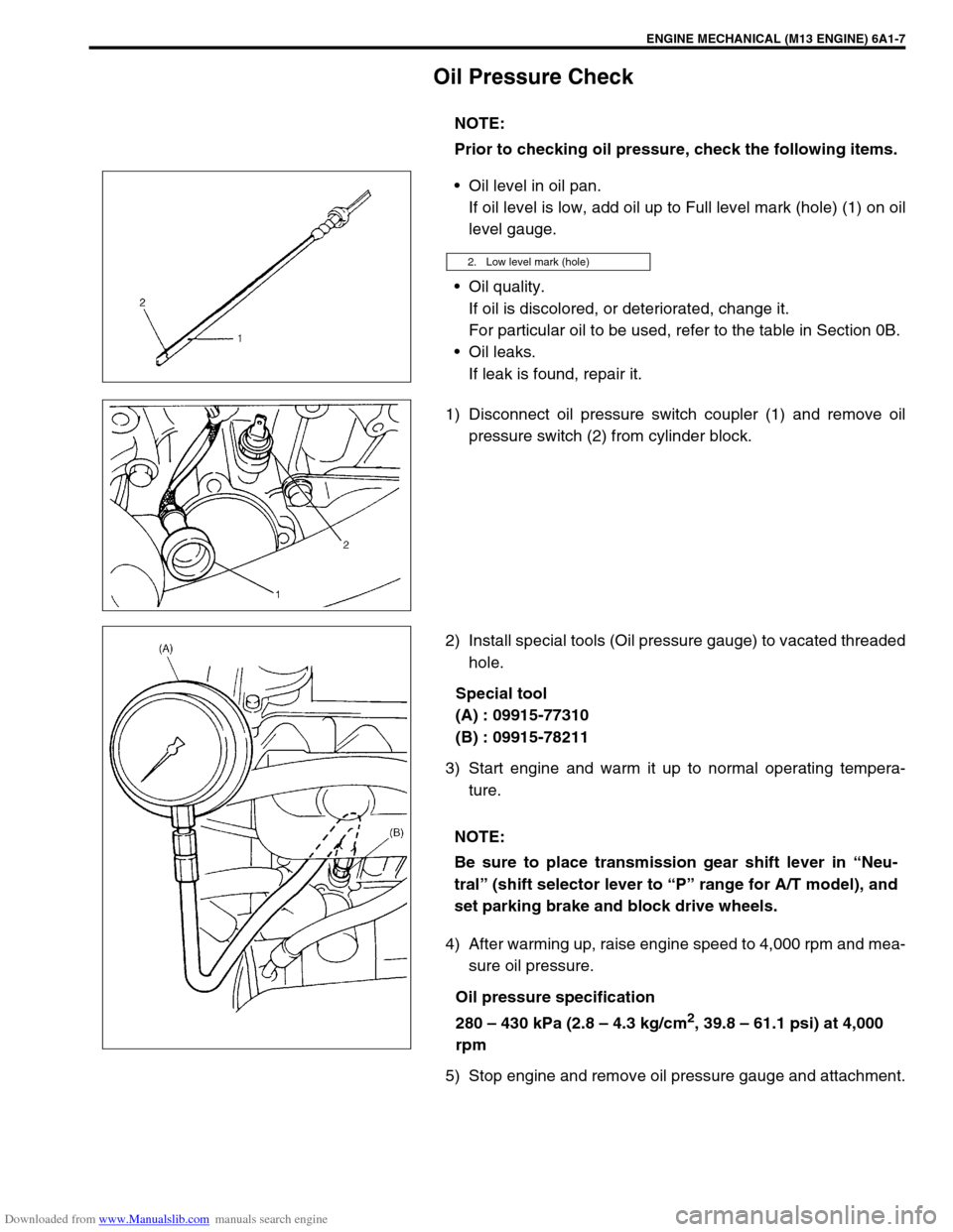
Oil Pressure Check
Oil level in oil pan.
If oil level is low, add oil up to Full level mark (hole) (1) on oil
level gauge.
Oil quality.
If oil is discolored, or deteriorated, change it.
For particular oil to be used, refer to the table in Section 0B.
Oil leaks.
If leak is found, repair it.
1) Disconnect oil pressure switch coupler (1) and remove oil
pressure switch (2) from cylinder block.
2) Install special tools (Oil pressure gauge) to vacated threaded
hole.
Special tool
(A) : 09915-77310
(B) : 09915-78211
3) Start engine and warm it up to normal operating tempera-
ture.
4) After warming up, raise engine speed to 4,000 rpm and mea-
sure oil pressure.
Oil pressure specification
280 – 430 kPa (2.8 – 4.3 kg/cm
2, 39.8 – 61.1 psi) at 4,000
rpm
5) Stop engine and remove oil pressure gauge and attachment.NOTE:
Prior to checking oil pressure, check the following items.
2. Low level mark (hole)
NOTE:
Be sure to place transmission gear shift lever in “Neu-
tral” (shift selector lever to “P” range for A/T model), and
set parking brake and block drive wheels.
Page 551 of 687

Downloaded from www.Manualslib.com manuals search engine 6A1-70 ENGINE MECHANICAL (M13 ENGINE)
INSTALLATION
1) Apply engine oil to pistons, rings, cylinder walls, connecting
rod bearings and crankpins.
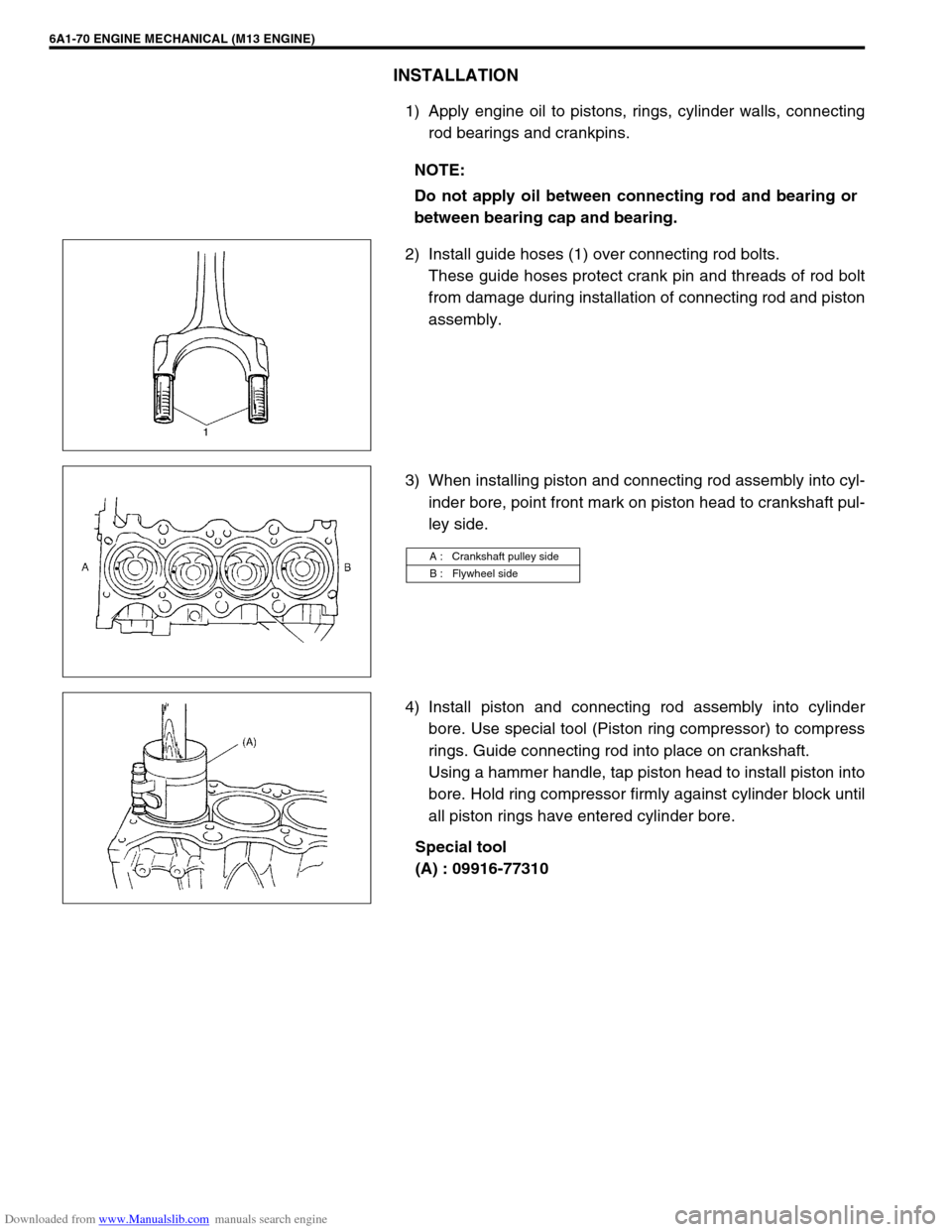
2) Install guide hoses (1) over connecting rod bolts.
These guide hoses protect crank pin and threads of rod bolt
from damage during installation of connecting rod and piston
assembly.
3) When installing piston and connecting rod assembly into cyl-
inder bore, point front mark on piston head to crankshaft pul-
ley side.
4) Install piston and connecting rod assembly into cylinder
bore. Use special tool (Piston ring compressor) to compress
rings. Guide connecting rod into place on crankshaft.
Using a hammer handle, tap piston head to install piston into
bore. Hold ring compressor firmly against cylinder block until
all piston rings have entered cylinder bore.
Special tool
(A) : 09916-77310 NOTE:
Do not apply oil between connecting rod and bearing or
between bearing cap and bearing.
A : Crankshaft pulley side
B : Flywheel side
Page 560 of 687
Downloaded from www.Manualslib.com manuals search engine ENGINE MECHANICAL (M13 ENGINE) 6A1-79
Main Bearings, Crankshaft and Cylinder Block
Tightening torque 4. Venturi plug 12. Input shaft bearing
Do not reuse. 5. Main bearing 13. Flywheel
Apply engine oil to inside / sliding
surface.6. Sensor plate 14. Main bearing cap
“a” : 3 mm (0.12 in.) 7. Crankshaft timing sprocket key 15. Flywheel mounting bolt
: Apply sealant 99000-31110 to thread
part.
“b” : 2 mm (0.08 in.) 8. Crankshaft 16. Rear oil seal housing mounting bolt
1. CKP sensor (if equipped) 9. Thrust bearing 17. Main bearing cap No.2 bolt
2. Knock sensor 10. Rear oil seal housing
: Apply specified amount [A] of seal-
ant 99000-31150 to mating surface. 18. Main bearing cap No.1 bolt
1) Tighten all bolts to 50 N·m (5.0 kg-m)
2) Then, turn all bolts to 60°
3. Cylinder block 11. Rear oil seal