Page 509 of 687
Downloaded from www.Manualslib.com manuals search engine 6A1-28 ENGINE MECHANICAL (M13 ENGINE)
Timing Chain Cover
REMOVAL
1) Disconnect negative cable at battery.
2) Remove A/C compressor and/or P/S pump belt (if
equipped).
3) Remove generator belt.
4) Drain engine oil.
[A] : Sealant application
amount3. Oil seal
: Apply engine oil to oil seal lip.8. Cylinder head cover
: Apply sealant 99000-31150 to the sealing
point for timing chain cover mating surface
and cylinder head gasket sealing point.
Refer to “Cylinder Head Cover Installation”.
“a” : 3 mm (0.12 in.) 4. Timing chain cover Tightening torque
: Apply sealant 99000-31140 to the mating surface
of cylinder and cylinder head.
: Apply sealant 99000-31150 to the mating surface
of timing chain cover referring to the figure of Step
1) in INSTALLATION.
“b” : 2 mm (0.08 in.) 5. Pin Do not reuse.
1. Crankshaft pulley bolt 6. Cylinder head cover gasket
2. Crankshaft pulley 7. Timing chain cover mounting bolts
Page 529 of 687
Downloaded from www.Manualslib.com manuals search engine 6A1-48 ENGINE MECHANICAL (M13 ENGINE)
Valves and Cylinder Head
1. Valve cotters 6. Intake valve 11. Cylinder head gasket
: “TOP” mark provided on gasket comes to
crankshaft pulley side, facing up.
2. Valve spring retainer 7. Exhaust valve 12. Knock pin
3. Valve spring 8. Valve guide Tightening torque
4. Valve stem seal 9. Cylinder head bolt
1) Tighten all bolts at 40 N·m (4.0 kg-m)
2) Turn all bolts to 60°
3) Then, turn all bolts to 60° once againDo not reuse.
5. Valve spring seat 10. Cylinder head
Apply engine oil to sliding surface of each
part.
Page 537 of 687

Downloaded from www.Manualslib.com manuals search engine 6A1-56 ENGINE MECHANICAL (M13 ENGINE)
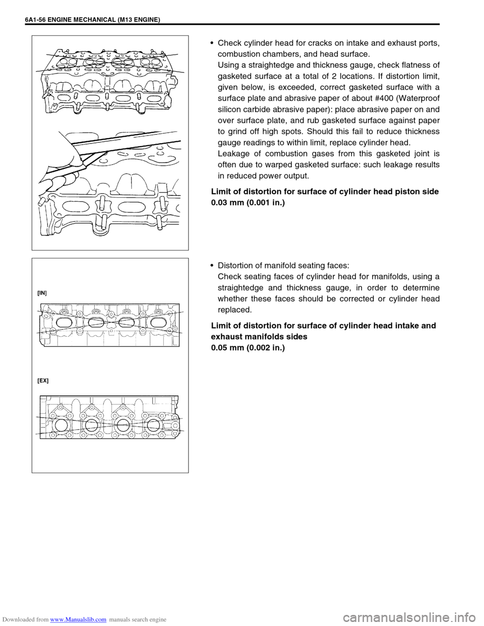
Check cylinder head for cracks on intake and exhaust ports,
combustion chambers, and head surface.
Using a straightedge and thickness gauge, check flatness of
gasketed surface at a total of 2 locations. If distortion limit,
given below, is exceeded, correct gasketed surface with a
surface plate and abrasive paper of about #400 (Waterproof
silicon carbide abrasive paper): place abrasive paper on and
over surface plate, and rub gasketed surface against paper
to grind off high spots. Should this fail to reduce thickness
gauge readings to within limit, replace cylinder head.
Leakage of combustion gases from this gasketed joint is
often due to warped gasketed surface: such leakage results
in reduced power output.
Limit of distortion for surface of cylinder head piston side
0.03 mm (0.001 in.)
Distortion of manifold seating faces:
Check seating faces of cylinder head for manifolds, using a
straightedge and thickness gauge, in order to determine
whether these faces should be corrected or cylinder head
replaced.
Limit of distortion for surface of cylinder head intake and
exhaust manifolds sides
0.05 mm (0.002 in.)
Page 540 of 687

Downloaded from www.Manualslib.com manuals search engine ENGINE MECHANICAL (M13 ENGINE) 6A1-59
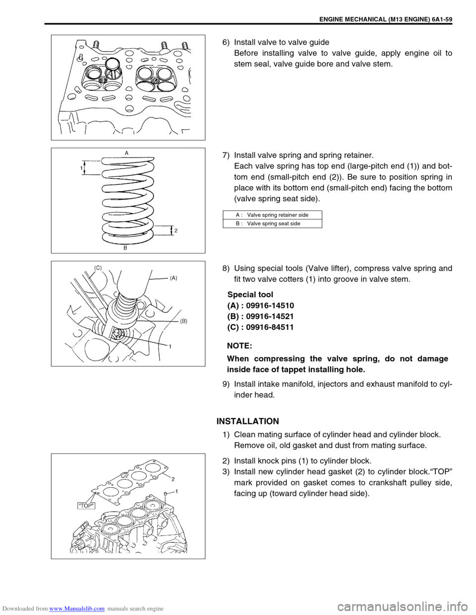
6) Install valve to valve guide
Before installing valve to valve guide, apply engine oil to
stem seal, valve guide bore and valve stem.
7) Install valve spring and spring retainer.
Each valve spring has top end (large-pitch end (1)) and bot-
tom end (small-pitch end (2)). Be sure to position spring in
place with its bottom end (small-pitch end) facing the bottom
(valve spring seat side).
8) Using special tools (Valve lifter), compress valve spring and
fit two valve cotters (1) into groove in valve stem.
Special tool
(A) : 09916-14510
(B) : 09916-14521
(C) : 09916-84511
9) Install intake manifold, injectors and exhaust manifold to cyl-
inder head.
INSTALLATION
1) Clean mating surface of cylinder head and cylinder block.
Remove oil, old gasket and dust from mating surface.
2) Install knock pins (1) to cylinder block.
3) Install new cylinder head gasket (2) to cylinder block.“TOP”
mark provided on gasket comes to crankshaft pulley side,
facing up (toward cylinder head side).
A : Valve spring retainer side
B : Valve spring seat side
NOTE:
When compressing the valve spring, do not damage
inside face of tappet installing hole.
Page 644 of 687

Downloaded from www.Manualslib.com manuals search engine ENGINE AND EMISSION CONTROL SYSTEM 6E-39
REMOVAL
1) Disconnect negative cable at battery.
2) Disconnect EGR valve connector.
3) Remove EGR pipe.
4) Remove EGR valve and gasket from cylinder head.
INSPECTION
1) Check resistance between following terminals of EGR valve
(1) in each pair.
If found faulty, replace EGR valve assembly.
EGR valve resistance
2) Remove carbon from EGR valve (1) gas passage.
3) Inspect valve (2), valve seat (3) and rod for fault, cracks,
bend or other damage.
If found faulty, replace EGR valve assembly.
INSTALLATION
Reverse removal procedure noting following.
Clean mating surface of valve and cylinder head.
Use new gaskets.
Evaporative emission (EVAP) control system
EVAP CANISTER PURGE INSPECTION
Terminal Standard resistance
A – B
C – B
F – E
D – E 20 – 24
Ω
ΩΩ Ω
NOTE:
Do not use any sharp-edged tool to remove carbon.
Be careful not to damage or bend EGR valve, valve seat
and rod.
NOTE:
Before inspection, check to make sure that gear shift
lever is in neutral position (with A/T model, selector lever
in “P” range) and that parking brake lever is pulled all the
way up.