Page 262 of 687

Downloaded from www.Manualslib.com manuals search engine BRAKES 5-1
6F1
6F2
6G
6H
6K
7A
7A1
7B1
7C1
7D
7E
5
9
10
10A
10B
9
10
10A
10B
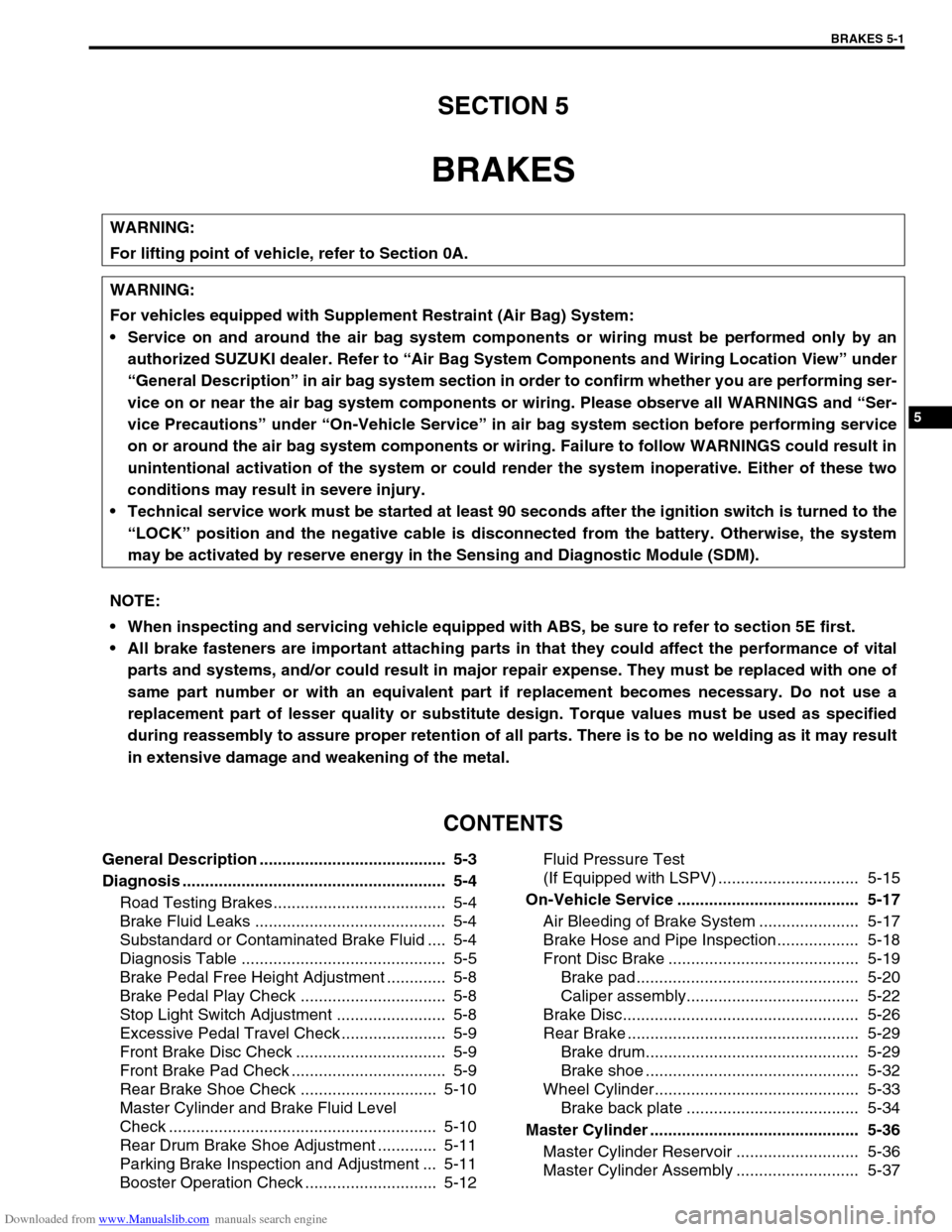
SECTION 5
BRAKES
CONTENTS
General Description ......................................... 5-3
Diagnosis .......................................................... 5-4
Road Testing Brakes ...................................... 5-4
Brake Fluid Leaks .......................................... 5-4
Substandard or Contaminated Brake Fluid .... 5-4
Diagnosis Table ............................................. 5-5
Brake Pedal Free Height Adjustment ............. 5-8
Brake Pedal Play Check ................................ 5-8
Stop Light Switch Adjustment ........................ 5-8
Excessive Pedal Travel Check ....................... 5-9
Front Brake Disc Check ................................. 5-9
Front Brake Pad Check .................................. 5-9
Rear Brake Shoe Check .............................. 5-10
Master Cylinder and Brake Fluid Level
Check ........................................................... 5-10
Rear Drum Brake Shoe Adjustment ............. 5-11
Parking Brake Inspection and Adjustment ... 5-11
Booster Operation Check ............................. 5-12Fluid Pressure Test
(If Equipped with LSPV) ............................... 5-15
On-Vehicle Service ........................................ 5-17
Air Bleeding of Brake System ...................... 5-17
Brake Hose and Pipe Inspection.................. 5-18
Front Disc Brake .......................................... 5-19
Brake pad ................................................. 5-20
Caliper assembly...................................... 5-22
Brake Disc.................................................... 5-26
Rear Brake ................................................... 5-29
Brake drum............................................... 5-29
Brake shoe ............................................... 5-32
Wheel Cylinder............................................. 5-33
Brake back plate ...................................... 5-34
Master Cylinder .............................................. 5-36
Master Cylinder Reservoir ........................... 5-36
Master Cylinder Assembly ........................... 5-37 WARNING:
For lifting point of vehicle, refer to Section 0A.
WARNING:
For vehicles equipped with Supplement Restraint (Air Bag) System:
Service on and around the air bag system components or wiring must be performed only by an
authorized SUZUKI dealer. Refer to “Air Bag System Components and Wiring Location View” under
“General Description” in air bag system section in order to confirm whether you are performing ser-
vice on or near the air bag system components or wiring. Please observe all WARNINGS and “Ser-
vice Precautions” under “On-Vehicle Service” in air bag system section before performing service
on or around the air bag system components or wiring. Failure to follow WARNINGS could result in
unintentional activation of the system or could render the system inoperative. Either of these two
conditions may result in severe injury.
Technical service work must be started at least 90 seconds after the ignition switch is turned to the
“LOCK” position and the negative cable is disconnected from the battery. Otherwise, the system
may be activated by reserve energy in the Sensing and Diagnostic Module (SDM).
NOTE:
When inspecting and servicing vehicle equipped with ABS, be sure to refer to section 5E first.
All brake fasteners are important attaching parts in that they could affect the performance of vital
parts and systems, and/or could result in major repair expense. They must be replaced with one of
same part number or with an equivalent part if replacement becomes necessary. Do not use a
replacement part of lesser quality or substitute design. Torque values must be used as specified
during reassembly to assure proper retention of all parts. There is to be no welding as it may result
in extensive damage and weakening of the metal.
Page 309 of 687
Downloaded from www.Manualslib.com manuals search engine 5-48 BRAKES
Brake Hose/Pipe
Front brake hose/pipe
For left-hand steering vehicle
[A] : For vehicle without ABS X : View X 5. Brake caliper 12. To front left brake caliper
[B] : For vehicle with ABS Y : View Y 6. 4 way joint 13. To rear brake
F : Front side Z : View Z 7. 5 way joint a-d: Clamp
R : Right side 1. E-ring 8. ABS hydraulic unit/control mod-
ule assemblyTightening torque
T : Top side 2. Flexible hose 9. P valve
V : View V 3. Hose washer 10. Hose bracket
W : View W 4. Hose bolt 11. To front right brake caliper
Page 310 of 687
Downloaded from www.Manualslib.com manuals search engine BRAKES 5-49
For right-hand steering vehicle
[A] : For vehicle without ABS X : View X 5. Brake caliper 12. To front left brake caliper
[B] : For vehicle with ABS Y : View Y 6. 4 way joint 13. To rear brake
F : Front side Z : View Z 7. 5 way joint 14. Front brake master cylinder
R : Right side 1. E-ring 8. ABS hydraulic unit a-f: Clamp
T : Top side 2. Flexible hose 9. P valve Tightening torque
V : View V 3. Hose washer 10. Hose bracket
W : View W 4. Hose bolt 11. To front right brake caliper
Page 684 of 687

Downloaded from www.Manualslib.com manuals search engine CHARGING SYSTEM 6H-17
Specifications
Battery
55B24R TYPE
38B20R TYPE
Generator
Tightening Torque Specification
Rated capacity 36 AH/5HR, 12 Volts
Electrolyte 3.1 L (6.55/5.46 US/lmp pt)
Electrolyte S.G. 1.28 when fully charged at 20 °C (68 °F)
Rated capacity 28 AH/5HR, 12 Volts
Electrolyte 2.1 L (4.44/3.70 US/lmp pt)
Electrolyte S.G. 1.28 when fully charged at 20 °C (68 °F)
Type 70 A type
Rated voltage 12 V
Nominal output 70 A
Permissible max. speed 18,000 r/min.
No-load speed 1,300 r/min (rpm)
Setting voltage 14.4 to 15.0 V
Permissible ambient temperature–30 to 90 °C (–22 to 194 °F)
Polarity Negative ground
Rotation Clockwise viewed from pulley side
Fastening partTightening torque
Nm kg-m lb-ft
Body ground bolt 8 0.8 6.0
Generator mounting bolts 23 2.3 16.5
“B” terminal inner nut 4.2 0.42 3.0
“B” terminal outer nut 8 0.8 6.0
Pulley nut 118 11.8 85.5
Rear end frame nuts
4.50.453.5
Rear end cover nuts
Rectifier “B” bolt 3.9 0.39 3.0
Stator stud bolts 8.8 0.88 6.5
Drive end bearing plate screws 2.6 0.26 2.0
Rectifier screws
2.00.201.5
Regulator and brush holder screws
Terminal plate bolt 3.8 0.38 3.0