2005 SUZUKI JIMNY crank
[x] Cancel search: crankPage 62 of 687

Downloaded from www.Manualslib.com manuals search engine AIR CONDITIONING (OPTIONAL) 1B-1
6F1
6F2
1B
7A
7A1
7B1
7C1
7D
7E
7F
8A
8B
8C
8D
8E
9
10
10A
10B
SECTION 1B
AIR CONDITIONING (OPTIONAL)
CONTENTS
General Description ....................................... 1B-3
Major Components and Location ................. 1B-3
Refrigerant Circulation ................................. 1B-4
Refrigerant Type .......................................... 1B-4
Diagnosis ........................................................ 1B-5
General Diagnosis Table .............................. 1B-5
Abnormal Noise Diagnosis ........................... 1B-7
Abnormal noise from compressor ............ 1B-7
Abnormal noise from magnetic clutch ...... 1B-7
Abnormal noise from tubing ..................... 1B-7
Abnormal noise from condenser .............. 1B-7
Abnormal noise from crankshaft pulley .... 1B-8
Abnormal noise from tension pulley ......... 1B-8
Abnormal noise from A/C evaporator ....... 1B-8
Abnormal noise from blower fan motor .... 1B-8
Quick Checking of Refrigerant Charge......... 1B-9Performance Diagnosis.............................. 1B-10
Performance diagnosis table.................. 1B-12
Detail diagnosis table (Ambient
temperature at 30°C (86°F)) .................. 1B-13
Compressor Drive Belt ............................... 1B-15
Electronical Diagnosis ................................ 1B-16
Wiring Diagram .......................................... 1B-16
A/C System Inspection of ECM and ITS
Circuits ....................................................... 1B-17
Refrigerant Recovery, Evacuating and
Charging ....................................................... 1B-21
Operation Procedure for Refrigerant
Charging .................................................... 1B-21
Recovery .................................................... 1B-22
Replenishing Compressor Oil .................... 1B-22 WARNING:
For vehicles equipped with Supplemental Restraint (Air Bag) System:
Service on and around the air bag system components or wiring must be performed only by an
authorized SUZUKI dealer. Refer to “Air Bag System Components and Wiring Location View” under
“General Description” in air bag system section in order to confirm whether you are performing ser-
vice on or near the air bag system components or wiring. Please observe all WARNINGS and “Ser-
vice Precautions” under “On-Vehicle Service” in air bag system section before performing service
on or around the air bag system components or wiring. Failure to follow WARNINGS could result in
unintentional activation of the system or could render the system inoperative. Either of these two
conditions may result in severe injury.
Technical service work must be started at least 90 seconds after the ignition switch is turned to the
“LOCK” position and the negative cable is disconnected from the battery. Otherwise, the system
may be activated by reserve energy in the Sensing and Diagnostic Module (SDM).
CAUTION:
The air conditioning system of this vehicle uses refrigerant HFC-134a (R-134a).
None of refrigerant, compressor oil and component parts is interchangeable between two types of
A/C: one using refrigerant HFC-134a (R-134a) and the other using refrigerant CFC-12 (R-12).
Be sure to check which refrigerant is used before any service work including inspection and mainte-
nance. For identification between these two types, refer to “Refrigerant Type” in this section.
When replenishing or changing refrigerant and compressor oil and when replacing parts, make sure
that the material or the part to be used is appropriate to the A/C installed in the vehicle being serviced.
Use of incorrect one will result in leakage of refrigerant, damage in parts or other faulty condition.
NOTE:
For basic servicing method of the air conditioning system that is not described in this section, refer to
AIR CONDITIONING BASIC MANUAL (Part number: 99520-02130).
Page 69 of 687

Downloaded from www.Manualslib.com manuals search engine 1B-8 AIR CONDITIONING (OPTIONAL)
Abnormal noise from crankshaft pulley
Abnormal noise from tension pulley
Abnormal noise from A/C evaporator
Abnormal noise from blower fan motor
Condition Possible Cause Correction
A large rattling noise
is heard at idle or sud-
den acceleration.Loosen crankshaft pulley bolt. Retighten bolt.
Condition Possible Cause Correction
Clattering noise is
heard from pulley.Worn or damaged bearing. Replace tension pulley.
Pulley cranks upon
contact.Cracked or loose bracket. Replace or retighten bracket.
Condition Possible Cause Correction
Whistling sound is
heard from A/C evapo-
rator.Depending on the combination of the interior /
exterior temperatures, engine rpm and refriger-
ant pressure, the refrigerant flowing out of the
expansion valve may, under certain conditions,
make a whistling sound.At times, slightly decreasing refrig-
erant volume may stop this noise.
Inspect expansion valve and
replace if faulty.
Condition Possible Cause Correction
Blower fan motor
emits a chirping
sound in proportion to
its speed of rotation.Worn or damaged motor brushes or commuta-
tor.Repair or replace blower fan motor.
Fluttering noise or
large droning noise is
heard from blower fan
motor.Leaves or other debris introduced from fresh air
inlet to blower fan motor.Remove debris and make sure that
the screen at fresh air inlet is intact.
Page 76 of 687

Downloaded from www.Manualslib.com manuals search engine AIR CONDITIONING (OPTIONAL) 1B-15
Compressor Drive Belt
INSPECTION
Check belt for wear and cracks, and replace as required.
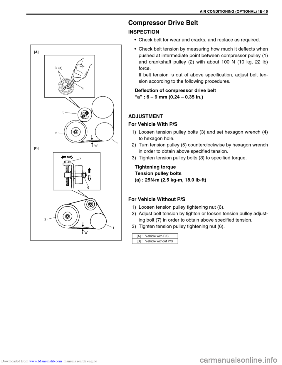
Check belt tension by measuring how much it deflects when
pushed at intermediate point between compressor pulley (1)
and crankshaft pulley (2) with about 100 N (10 kg, 22 lb)
force.
If belt tension is out of above specification, adjust belt ten-
sion according to the following procedures.
Deflection of compressor drive belt
“a” : 6 – 9 mm (0.24 – 0.35 in.)
ADJUSTMENT
For Vehicle With P/S
1) Loosen tension pulley bolts (3) and set hexagon wrench (4)
to hexagon hole.
2) Turn tension pulley (5) counterclockwise by hexagon wrench
in order to obtain above specified tension.
3) Tighten tension pulley bolts (3) to specified torque.
Tightening torque
Tension pulley bolts
(a) : 25N·m (2.5 kg-m, 18.0 lb-ft)
For Vehicle Without P/S
1) Loosen tension pulley tightening nut (6).
2) Adjust belt tension by tighten or loosen tension pulley adjust-
ing bolt (7) in order to obtain above specified tension.
3) Tighten tension pulley tightening nut (6).
[A] : Vehicle with P/S
[B] : Vehicle without P/S
Page 137 of 687

Downloaded from www.Manualslib.com manuals search engine 3B1-6 POWER STEERING (P/S) SYSTEM (If equipped)
Power Steering Belt Check
INSPECTION
Check that belt is free from any damage and properly fitted
in pulley groove.
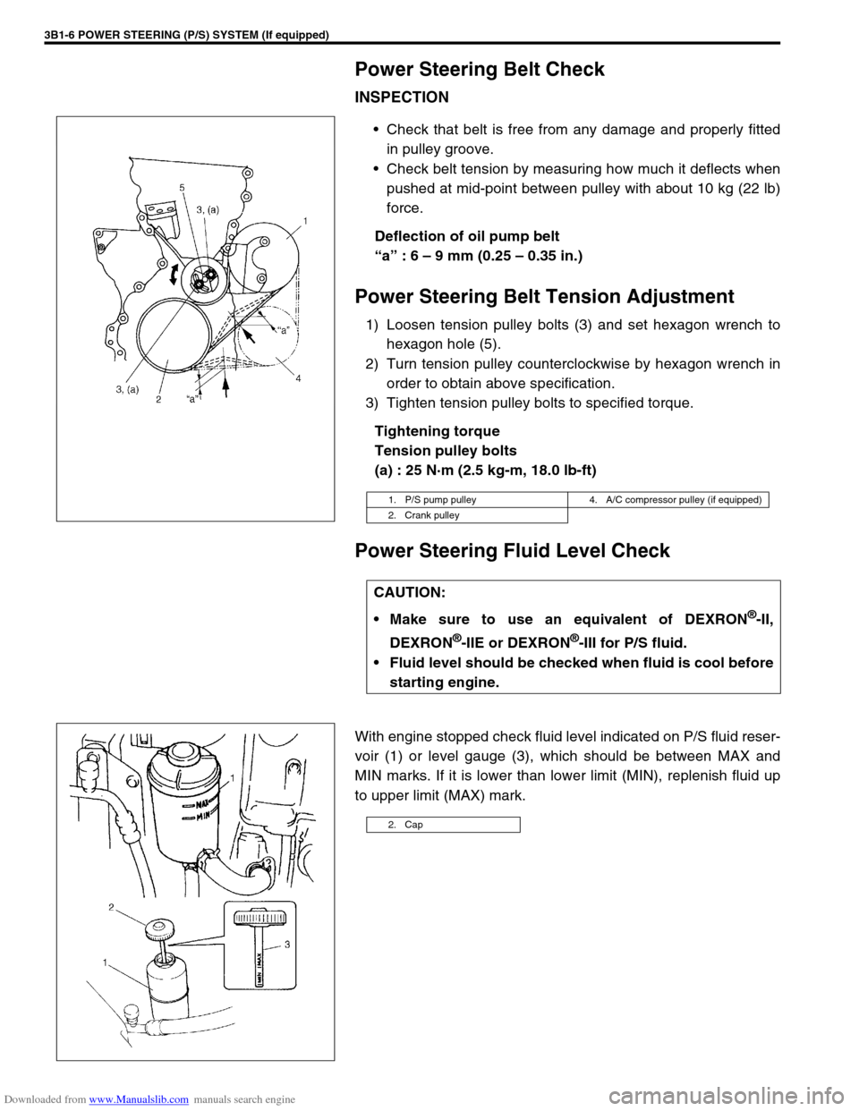
Check belt tension by measuring how much it deflects when
pushed at mid-point between pulley with about 10 kg (22 lb)
force.
Deflection of oil pump belt
“a” : 6 – 9 mm (0.25 – 0.35 in.)
Power Steering Belt Tension Adjustment
1) Loosen tension pulley bolts (3) and set hexagon wrench to
hexagon hole (5).
2) Turn tension pulley counterclockwise by hexagon wrench in
order to obtain above specification.
3) Tighten tension pulley bolts to specified torque.
Tightening torque
Tension pulley bolts
(a) : 25 N·m (2.5 kg-m, 18.0 lb-ft)
Power Steering Fluid Level Check
With engine stopped check fluid level indicated on P/S fluid reser-
voir (1) or level gauge (3), which should be between MAX and
MIN marks. If it is lower than lower limit (MIN), replenish fluid up
to upper limit (MAX) mark.
1. P/S pump pulley 4. A/C compressor pulley (if equipped)
2. Crank pulley
CAUTION:
Make sure to use an equivalent of DEXRON
®-II,
DEXRON
®-IIE or DEXRON®-III for P/S fluid.
Fluid level should be checked when fluid is cool before
starting engine.
2. Cap
Page 143 of 687

Downloaded from www.Manualslib.com manuals search engine 3B1-12 POWER STEERING (P/S) SYSTEM (If equipped)
On-Vehicle Service
Power Steering Belt
REMOVAL
1) Disconnect negative cable at battery.
2) Loosen tension pulley bolts (2).
3) Remove power steering belt (1).
INSPECTION
Check power steering belt for wear and cracks, and replace
as required.
INSTLLATION
1) Install belt to power steering pump pulley (1), crankshaft pul-
ley (2), A/C pulley (if equipped) (3) and tension pulley (4).
2) Adjust belt tension referring to “Power Steering Belt Check”
in this section.
Power Steering (P/S) Pump
REMOVAL
1) Take out fluid in P/S fluid reservoir with syringe or such.
2) Remove P/S belt.
3) Disconnect high pressure hose and low pressure hose.
4) Disconnect pressure switch lead harness.
Page 358 of 687

Downloaded from www.Manualslib.com manuals search engine ENGINE GENERAL INFORMATION AND DIAGNOSIS 6-1
6F2
6G
6H
6K
7A
7A1
7B1
7C1
7D
7E
7F
8B
6
8D
8E
8B
9
10A
10B
SECTION 6
ENGINE GENERAL INFORMATION AND
DIAGNOSIS
GENERAL INFORMATION AND ENGINE DIAGNOSIS ..............................................................................
6-1
ENGINE MECHANICAL ...........................................................................................................................
6A1-1
ENGINE COOLING.....................................................................................................................................
6B-1
ENGINE FUEL ............................................................................................................................................
6C-1
ENGINE AND EMISSION CONTROL SYSTEM ........................................................................................
6E-1
IGNITION SYSTEM ....................................................................................................................................
6F-1
CRANKING SYSTEM .................................................................................................................................
6G-1
CHARGING SYSTEM .................................................................................................................................
6H-1
EXHAUST SYSTEM ...................................................................................................................................
6K-1
CONTENTS
General Information .......................................... 6-3
Statement on Cleanliness and Care ............... 6-3
General Information on Engine Service .......... 6-3
Precaution on fuel system service............... 6-4
Fuel pressure relief procedure .................... 6-5
Fuel leakage check procedure .................... 6-5
Engine Diagnosis .............................................. 6-6
General Description ........................................ 6-6
On-Board Diagnostic System (Vehicle with
Immobilizer Indicator Lamp) ............................ 6-6On-Board Diagnostic System (Vehicle without
Immobilizer Indicator Lamp)............................ 6-9
Precaution in Diagnosing Trouble ................. 6-10
Engine Diagnostic Flow Table ...................... 6-11
Customer problem inspection form
(example) .................................................. 6-13
Malfunction indicator lamp (MIL) check..... 6-14
Diagnostic trouble code (DTC) check ....... 6-14
Diagnostic trouble code (DTC)
clearance................................................... 6-15 WARNING:
For vehicles equipped with Supplemental Restraint (Air Bag) System :
Service on and around the air bag system components or wiring must be performed only by an
authorized SUZUKI dealer. Refer to “Air Bag System Components and Wiring Location View” under
“General Description” in air bag system section in order to confirm whether you are performing ser-
vice on or near the air bag system components or wiring. Please observe all WARNINGS and “Ser-
vice Precautions” under “On-Vehicle Service” in air bag system section before performing service
on or around the air bag system components or wiring. Failure to follow WARNINGS could result in
unintentional activation of the system or could render the system inoperative. Either of these two
conditions may result in severe injury.
Technical service work must be started at least 90 seconds after the ignition switch is turned to the
“LOCK” position and the negative cable is disconnected from the battery. Otherwise, the system
may be activated by reserve energy in the Sensing and Diagnostic Module (SDM).
NOTE:
Whether the following systems (parts) are used in the particular vehicle or not depends on vehicle
specifications. Be sure to bear this in mind when performing service work.
EGR valve
Heated oxygen sensor(s) or CO adjusting resistor
Three-way catalytic converter (TWC) and warm up three-way catalytic converter (WU-TWC)
Page 359 of 687

Downloaded from www.Manualslib.com manuals search engine 6-2 ENGINE GENERAL INFORMATION AND DIAGNOSIS
Diagnostic trouble code (DTC) table ......... 6-16
Fail-safe table............................................ 6-19
Visual inspection ....................................... 6-20
Engine basic inspection ............................ 6-21
Engine diagnosis table .............................. 6-23
Scan Tool Data ............................................. 6-28
Scan tool data definitions .......................... 6-30
Inspection of ECM and Its Circuits ................ 6-33
Component Location ..................................... 6-42
Table A-1 Malfunction Indicator Lamp Circuit
Check - Lamp Does Not Come “ON” at Ignition
Switch ON (But Engine at Stop).................... 6-43
Table A-2 Malfunction Indicator Lamp Circuit
Check - Lamp Remains “ON” after Engine
Starts............................................................. 6-44
Table A-3 Malfunction Indicator Lamp Circuit
Check - Mil Flashes at Ignition Switch ON .... 6-45
Table A-4 Malfunction Indicator Lamp Circuit
Check - MIL Does Not Flash, Just Remains
ON or Just Remains OFF Even with Grounding
Diagnosis Switch Terminal............................ 6-45
Table A-5 ECM Power and Ground Circuit
Check - MIL Doesn’t Light at Ignition Switch
ON and Engine Doesn’t Start Though It Is
Cranked Up ................................................... 6-46
DTC P0105 (DTC No.11) Manifold Absolute
Pressure (MAP) Circuit Malfunction .............. 6-48
DTC P0110 (DTC No.18) Intake Air Temp.
(IAT) Circuit Malfunction ............................... 6-51
DTC P0115 (DTC No.19) Engine Coolant
Temperature (ECT) Circuit Malfunction ........ 6-53
DTC P0120 (DTC No.13) Throttle Position
Circuit Malfunction ........................................ 6-55
DTC P0121 Throttle Position Circuit Range /
Performance Problem ................................... 6-57
DTC P0130 (DTC No.14) Heated Oxygen
Sensor (HO2S) Circuit Malfunction
(Sensor-1) ..................................................... 6-59
DTC P0133 Heated Oxygen Sensor (HO2S)
Circuit Slow Response (Sensor-1) ................ 6-61
DTC P0135 (DTC No.14) Heated Oxygen
Sensor (HO2S) Heater Circuit Malfunction
(Sensor-1) ..................................................... 6-62
DTC P0136 Heated Oxygen Sensor (HO2S)
Circuit Malfunction (Sensor-2) ...................... 6-64
DTC P0141 Heated Oxygen Sensor (HO2S)
Heater Circuit Malfunction (Sensor-2)........... 6-66
DTC P0171 Fuel System Too Lean .............. 6-68
DTC P0172 Fuel System Too Rich ............... 6-68
DTC P0300 Random Misfire Detected
(Misfire Detected at 2 or More Cylinders) ..... 6-72DTC P0301 Cylinder 1 Misfire Detected ........ 6-72
DTC P0302 Cylinder 2 Misfire Detected ........ 6-72
DTC P0303 Cylinder 3 Misfire Detected ........ 6-72
DTC P0304 Cylinder 4 Misfire Detected ........ 6-72
DTC P0325 (DTC No.17) Knock Sensor Circuit
Malfunction .................................................... 6-77
DTC P0335 (DTC No.23) Crankshaft Position
(CKP) Sensor Circuit Malfunction .................. 6-79
DTC P0340 (DTC No.15) Camshaft Position
(CMP) Sensor Circuit Malfunction ................. 6-82
DTC P0400 Exhaust Gas Recirculation Flow
Malfunction .................................................... 6-85
DTC P0420 Catalyst System Efficiency below
Threshold ....................................................... 6-88
DTC P0443 Purge Control Valve Circuit
Malfunction .................................................... 6-91
DTC P0481 A/C Condenser Fan Control
Circuit Malfunction ......................................... 6-92
DTC P0500 (DTC No.16) Vehicle Speed
Sensor (VSS) Malfunction ............................. 6-94
DTC P0505 Idle Control System
Malfunction .................................................... 6-96
DTC P0601 Internal Control Module Memory
Check Sum Error (DTC No.71) ...................... 6-98
DTC P1450 Barometric Pressure Sensor
Low / High Input ............................................. 6-99
DTC P1451 Barometric Pressure Sensor
Performance Problem .................................... 6-99
DTC P1500 Engine Starter Signal Circuit
Malfunction .................................................. 6-101
DTC P1510 ECM Back-up Power Supply
Malfunction .................................................. 6-103
DTC P1570 (DTC No.21) ABS Signal Circuit
Malfunction .................................................. 6-104
DTC P1600 Serial Communication Problem
Between ECM and TCM .............................. 6-105
DTC P1717 A/T Drive Range (Park / Neutral
Position) Signal Circuit Malfunction ............. 6-107
Table B-1 Fuel Injector Circuit Check ..........6-109
Table B-2 Fuel Pump and Its Circuit
Check........................................................... 6-110
Table B-3 Fuel Pressure Check................... 6-112
Table B-4 Idle Air Control System Check ....6-114
Table B-5 A/C Signal Circuits Check
(Vehicle with A/C) ........................................ 6-117
Table B-6 Electric Load Signal Circuit
Check........................................................... 6-119
TAble B-7 A/C Condenser Fan Control
System Check.............................................. 6-121
Special Tool ................................................... 6-123
Page 360 of 687

Downloaded from www.Manualslib.com manuals search engine ENGINE GENERAL INFORMATION AND DIAGNOSIS 6-3
General Information
Statement on Cleanliness and Care
An automobile engine is a combination of many machined, honed, polished and lapped surfaces with tolerances
that are measured in the thousands of an millimeter (ten thousands of an inch).
Accordingly, when any internal engine parts are serviced, care and cleanliness are important.
Throughout this section, it should be understood that proper cleaning and protection of machined surfaces and
friction areas is part of the repair procedure. This is considered standard shop practice even if not specifically
stated.
A liberal coating of engine oil should be applied to friction areas during assembly to protect and lubricate the
surfaces on initial operation.
Whenever valve train components, pistons, piston rings, connecting rods, rod bearings, and crankshaft jour-
nal bearings are removed for service, they should be retained in order.
At the time of installation, they should be installed in the same locations and with the same mating surfaces
as when removed.
Battery cables should be disconnected before any major work is performed on the engine.
Failure to disconnect cables may result in damage to wire harness or other electrical parts.
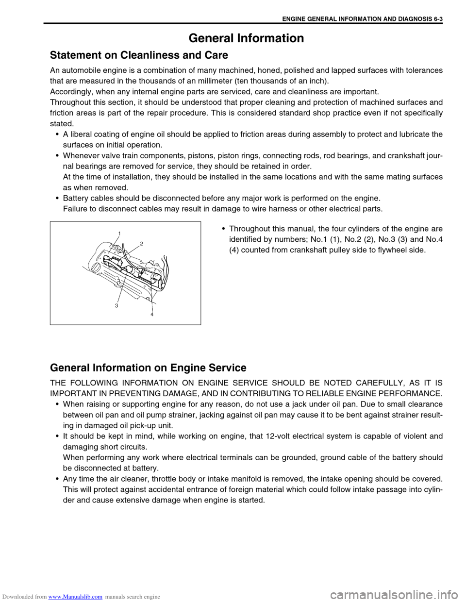
Throughout this manual, the four cylinders of the engine are
identified by numbers; No.1 (1), No.2 (2), No.3 (3) and No.4
(4) counted from crankshaft pulley side to flywheel side.
General Information on Engine Service
THE FOLLOWING INFORMATION ON ENGINE SERVICE SHOULD BE NOTED CAREFULLY, AS IT IS
IMPORTANT IN PREVENTING DAMAGE, AND IN CONTRIBUTING TO RELIABLE ENGINE PERFORMANCE.
When raising or supporting engine for any reason, do not use a jack under oil pan. Due to small clearance
between oil pan and oil pump strainer, jacking against oil pan may cause it to be bent against strainer result-
ing in damaged oil pick-up unit.
It should be kept in mind, while working on engine, that 12-volt electrical system is capable of violent and
damaging short circuits.
When performing any work where electrical terminals can be grounded, ground cable of the battery should
be disconnected at battery.
Any time the air cleaner, throttle body or intake manifold is removed, the intake opening should be covered.
This will protect against accidental entrance of foreign material which could follow intake passage into cylin-
der and cause extensive damage when engine is started.