2005 SUZUKI JIMNY ECU
[x] Cancel search: ECUPage 87 of 687

Downloaded from www.Manualslib.com manuals search engine 1B-26 AIR CONDITIONING (OPTIONAL)
2) Connect Low charging hose (1) and High charging hose (2)
of the manifold gauge set (3) in position. Thus open refriger-
ant container valve (4) to purge the charging line.
3) Open the high pressure side valve (5) and charge refrigerant
to system.
4) After a while, open the low pressure side valve (6) and close
the high pressure side valve (5).
5) Start engine and keep engine speed at 1500 r/min. Then,
operate air conditioning.
6) Charge A/C system with refrigerant in vapor state. At this
time, refrigerant container should be held upright.
7) When refrigerant container (3) is emptied, use the following
procedure to replace refrigerant container with a new refrig-
erant container (3).
a) Close low pressure valve.
b) Replace empty container (3) with a refrigerant container
which has been charged with refrigerant. When using
refrigerant container tap valve (4), use the following proce-
dure for replacement.
i) Retract needle (1) and remove refrigerant container tap
valve (4) by loosening its plate nut (2).
ii) Install previously-removed refrigerant container tap valve
(4) to a new refrigerant container (3).
c) Purge any air existing in center charging hose
When using refrigerant container tap valve, use the follow-
ing procedure to purge air.
i) Once fully tighten refrigerant container tap valve (1), and
then loosen (open) plate nut (2) slightly.
ii) Open low pressure side valve (3) of manifold gauge set
(4) a little.
iii) As soon as refrigerant comes out with a “hiss” through a
clearance between refrigerant container and tap valve,
tighten plate nut (2) as well as low pressure side valve (3).
iv) Turn handle of tap valve (1) clockwise so that its needle is
screwed into the new container to make a hole for refriger-
ant flow. WARNING:
Make sure that high pressure side valve is closed
securely.
Page 146 of 687

Downloaded from www.Manualslib.com manuals search engine POWER STEERING (P/S) SYSTEM (If equipped) 3B1-15
Check free length of relief valve spring (1).
Replace pump assembly if any defective is found.
Relief valve spring free length
Standard : 36.5 mm (1.44 in.)
Limit : 33.5 mm (1.32 in.)
ASSEMBLY
Reverse disassembly procedure for assembly, noting the follow-
ing.
1) Apply power steering fluid to shaft (2) outer surface and
grease to oil seal lip (1) and insert it from oil seal side.
“A” : Grease 99000-25010
2) Apply power steering fluid to O-rings and fit them to pump
body.
3) Install side plate (2) to pump body.
4) Apply power steering fluid to sliding surface of rotor (1).
5) Install rotor (1) to shaft, directing “dot” (2) marked side of
rotor toward pump cover (facing up).
6) Install new snap ring to shaft, then make sure to fit snap ring
into shaft groove securely.
NOTE:
Carefully align the dowel pins (3) on the side plate (2) at
bolt hole (1) as shown in figure.
NOTE:
Never reuse the removed snap ring.
Page 158 of 687

Downloaded from www.Manualslib.com manuals search engine STEERING WHEEL AND COLUMN 3C-5
Check air bag (inflator) module visually and if any of the following
is found, replace it with a new one.
Air bag being deployed
Trim cover (1) (pad surface) being cracked
Wire harness (3) or connector being damaged
Air bag (inflator) module being damaged or having been
exposed to strong impact (dropped)
INSTALLATION
1) Check that horn wire is connected to horn terminal securely.
2) Connect yellow connector (1) of driver air bag (inflator) mod-
ule (3) pushing connector till it is locked.
3) Install driver air bag (inflator) module to steering wheel, tak-
ing care so that no part of wire harness is caught between
them.
4) Make sure that clearance between module and steering
wheel is uniform all the way.
5) Tighten driver air bag (inflator) module mounting bolts (1) to
specified torque.
Tightening torque
Driver air bag (inflator) module mounting bolts
(a) : 9 N·m (0.9 kg-m, 6.5 lb-ft)
6) Install steering wheel side cap (2).
7) Connect negative battery cable.
8) Enable air bag system. Refer to “Enabling Air Bag System”
under “Service Precautions” in Section 10B.
Steering Wheel
2. Inflator case
CAUTION:
For vehicle with air bag system
Removal of the steering wheel allows the contact coil to
turn freely but do not turn the contact coil (on the combi-
nation switch) more than allowable number of turns
(about two and a half turns from the center position
clockwise or counterclockwise respectively), or coil will
break.
Page 161 of 687

Downloaded from www.Manualslib.com manuals search engine 3C-8 STEERING WHEEL AND COLUMN
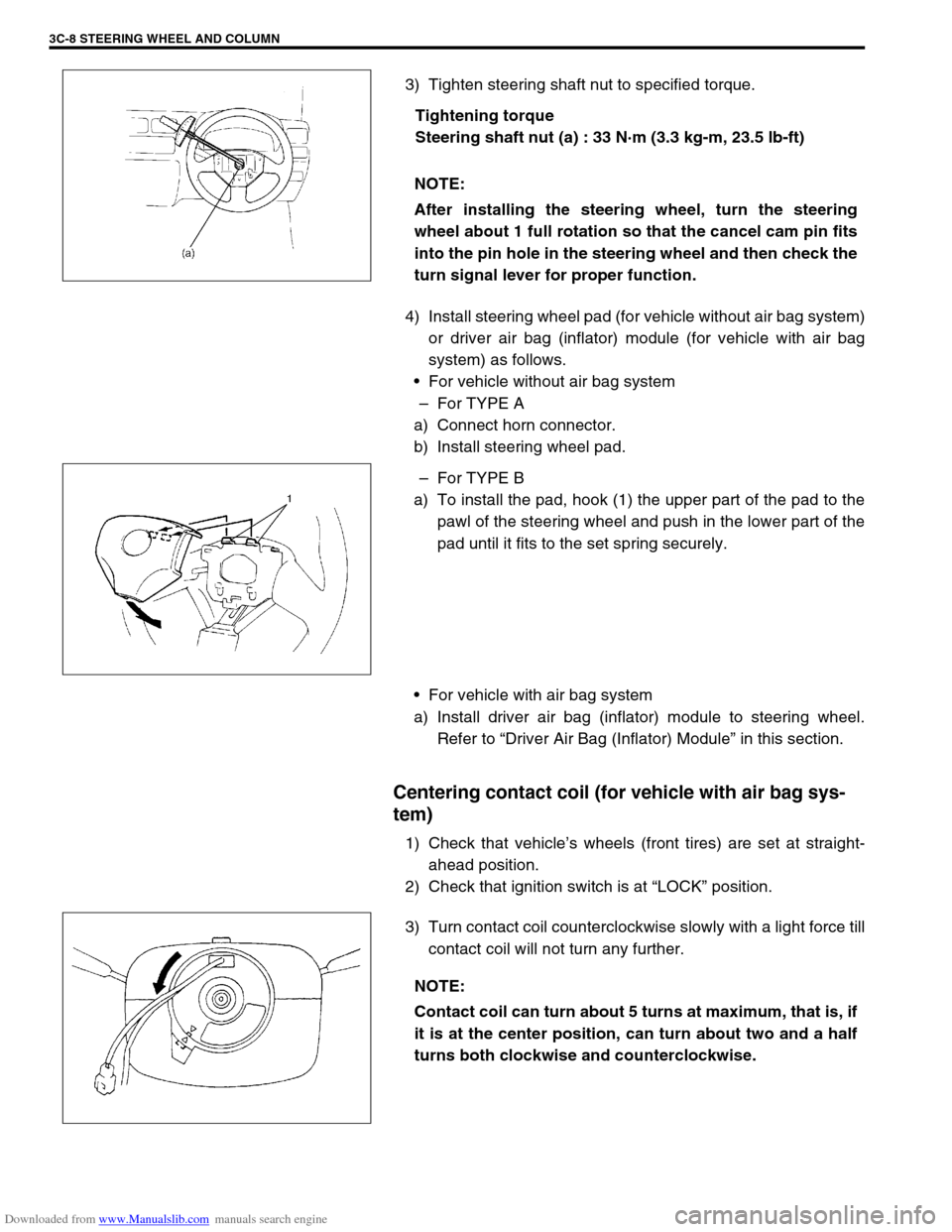
3) Tighten steering shaft nut to specified torque.
Tightening torque
Steering shaft nut (a) : 33 N·m (3.3 kg-m, 23.5 lb-ft)
4) Install steering wheel pad (for vehicle without air bag system)
or driver air bag (inflator) module (for vehicle with air bag
system) as follows.
For vehicle without air bag system
–For TYPE A
a) Connect horn connector.
b) Install steering wheel pad.
–For TYPE B
a) To install the pad, hook (1) the upper part of the pad to the
pawl of the steering wheel and push in the lower part of the
pad until it fits to the set spring securely.
For vehicle with air bag system
a) Install driver air bag (inflator) module to steering wheel.
Refer to “Driver Air Bag (Inflator) Module” in this section.
Centering contact coil (for vehicle with air bag sys-
tem)
1) Check that vehicle’s wheels (front tires) are set at straight-
ahead position.
2) Check that ignition switch is at “LOCK” position.
3) Turn contact coil counterclockwise slowly with a light force till
contact coil will not turn any further. NOTE:
After installing the steering wheel, turn the steering
wheel about 1 full rotation so that the cancel cam pin fits
into the pin hole in the steering wheel and then check the
turn signal lever for proper function.
NOTE:
Contact coil can turn about 5 turns at maximum, that is, if
it is at the center position, can turn about two and a half
turns both clockwise and counterclockwise.
Page 166 of 687

Downloaded from www.Manualslib.com manuals search engine STEERING WHEEL AND COLUMN 3C-13
8) If equipped with shift (key) interlock cable (1), remove shift
(key) interlock cable screw (2) and then disconnect its cable
from ignition switch in order a) – c) as shown in the figure.
9) Remove steering column from vehicle.
10) Remove steering column seal (1) from steering column lower
bracket.
INSPECTION
CHECKING PROCEDURE
1) Check that two capsules (1) are attached to steering column
bracket (2) securely. Check clearance between capsules and
steering column bracket. Clearance should be 0.0 mm (0.0
in.) on both sides.
If found loose or clearance, replace steering column assem-
bly.
2) Check two plates (3) for any damages such as crack or
breakage.
If anything is found faulty, replace as steering column
assembly.
CAUTION:
Don’t separate double tube type steering column assem-
bly into steering column and shaft. If column or shaft is
defective, replace as and assembly.
NOTE:
Vehicles involved in accidents resulting in body damage,
where steering column has been impacted (or air bag
deployed), may have a damaged or misaligned steering
column.
Page 167 of 687

Downloaded from www.Manualslib.com manuals search engine 3C-14 STEERING WHEEL AND COLUMN
3) Take measurement “a” as shown.
If it is shorter than specified length, replace column assem-
bly (1) with new one.
Steering column assembly length
“a” : 733.2 – 734.8 mm (28.87 – 28.93 in.)
4) Check steering shaft joints and shaft for any damages such
as crack, breakage, malfunction or excessive play.
If anything is found faulty, replace as lower joint assembly or
column assembly.
5) Check steering shaft for smooth rotation.
If found defective, replace as column assembly.
6) Check steering shaft and column for bend, cracks or defor-
mation.
If found defective, replace.
7) Check steering column lower seal (1) for breakage or defor-
mation. If found defective, replace.
INSTALLATION
1) Be sure that front wheels and steering wheel are in straight
forward state.
2) If equipped, install shift (key) interlock cable to ignition
switch.
3) Apply sealant to the steering column lower bracket (shaded
section in the figure) and fit the steering column seal (1) to
the stepped part of the steering column lower bracket
securely.
“A” : Sealant 99000-31090
CAUTION:
After tightening steering column mounting bolts and
nuts shaft joint bolts should be tightened.
Page 171 of 687

Downloaded from www.Manualslib.com manuals search engine 3C-18 STEERING WHEEL AND COLUMN
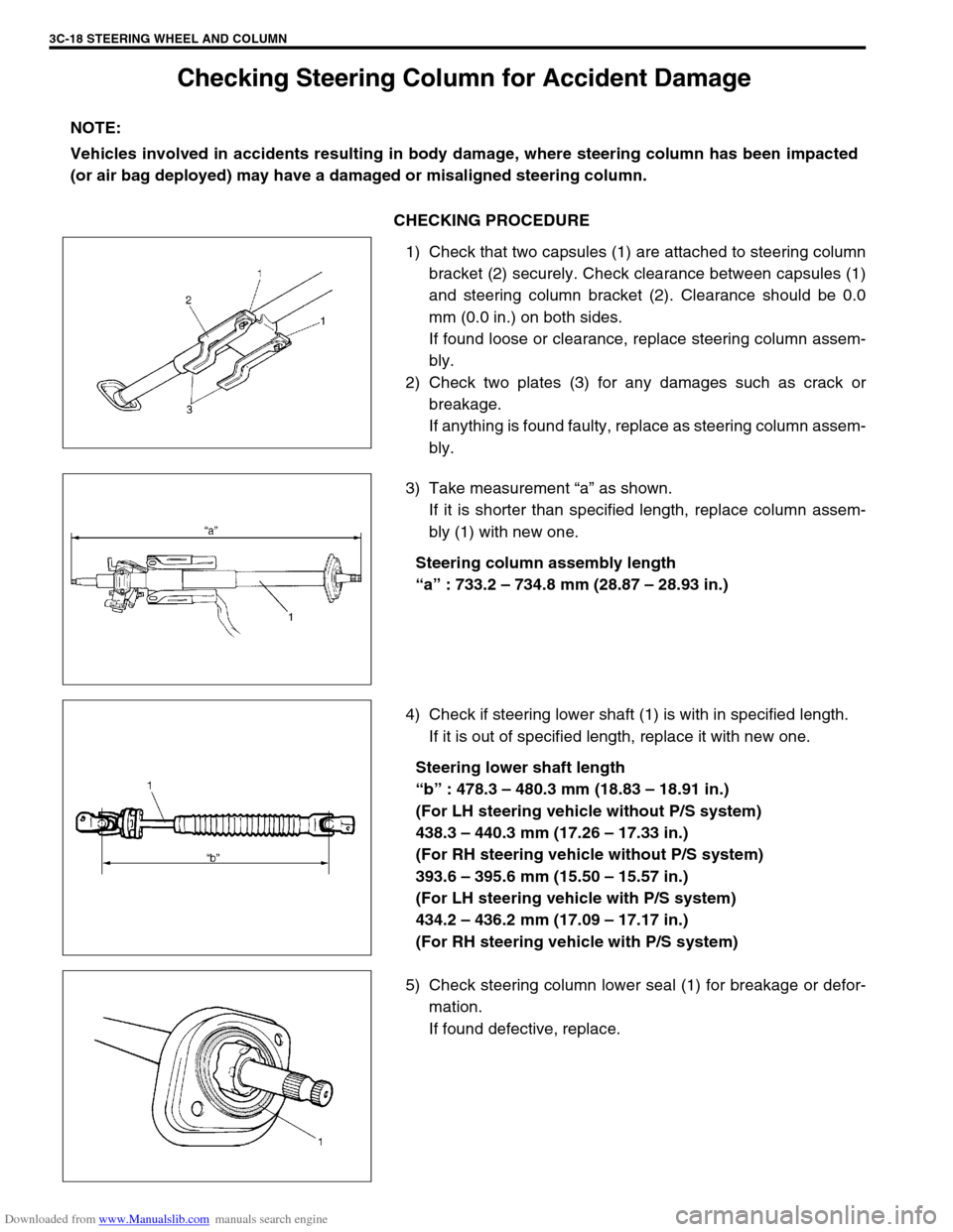
Checking Steering Column for Accident Damage
CHECKING PROCEDURE
1) Check that two capsules (1) are attached to steering column
bracket (2) securely. Check clearance between capsules (1)
and steering column bracket (2). Clearance should be 0.0
mm (0.0 in.) on both sides.
If found loose or clearance, replace steering column assem-
bly.
2) Check two plates (3) for any damages such as crack or
breakage.
If anything is found faulty, replace as steering column assem-
bly.
3) Take measurement “a” as shown.
If it is shorter than specified length, replace column assem-
bly (1) with new one.
Steering column assembly length
“a” : 733.2 – 734.8 mm (28.87 – 28.93 in.)
4) Check if steering lower shaft (1) is with in specified length.
If it is out of specified length, replace it with new one.
Steering lower shaft length
“b” : 478.3 – 480.3 mm (18.83 – 18.91 in.)
(For LH steering vehicle without P/S system)
438.3 – 440.3 mm (17.26 – 17.33 in.)
(For RH steering vehicle without P/S system)
393.6 – 395.6 mm (15.50 – 15.57 in.)
(For LH steering vehicle with P/S system)
434.2 – 436.2 mm (17.09 – 17.17 in.)
(For RH steering vehicle with P/S system)
5) Check steering column lower seal (1) for breakage or defor-
mation.
If found defective, replace. NOTE:
Vehicles involved in accidents resulting in body damage, where steering column has been impacted
(or air bag deployed) may have a damaged or misaligned steering column.
Page 239 of 687

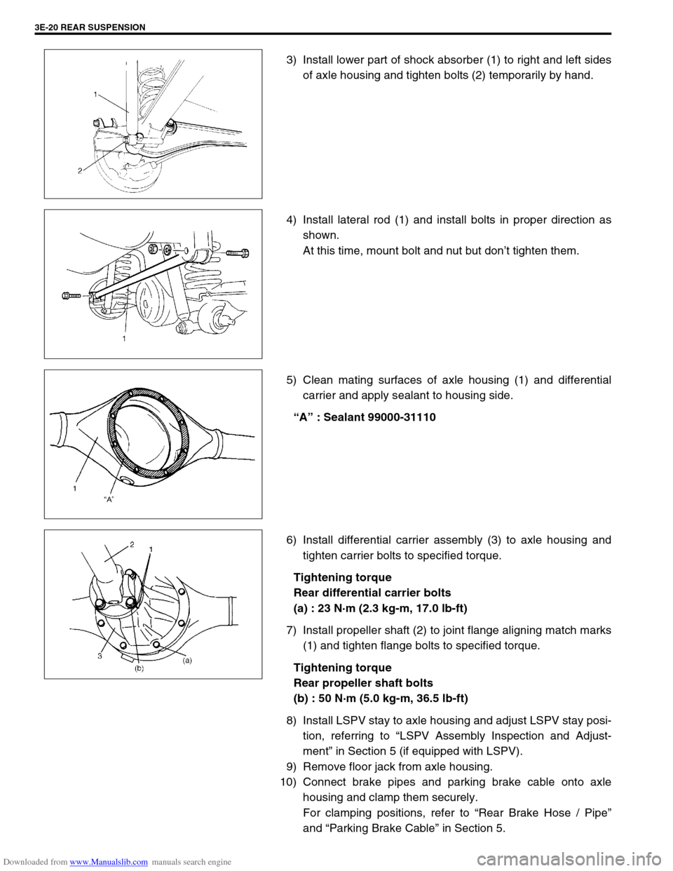
Downloaded from www.Manualslib.com manuals search engine 3E-20 REAR SUSPENSION
3) Install lower part of shock absorber (1) to right and left sides
of axle housing and tighten bolts (2) temporarily by hand.
4) Install lateral rod (1) and install bolts in proper direction as
shown.
At this time, mount bolt and nut but don’t tighten them.
5) Clean mating surfaces of axle housing (1) and differential
carrier and apply sealant to housing side.
“A” : Sealant 99000-31110
6) Install differential carrier assembly (3) to axle housing and
tighten carrier bolts to specified torque.
Tightening torque
Rear differential carrier bolts
(a) : 23 N·m (2.3 kg-m, 17.0 lb-ft)
7) Install propeller shaft (2) to joint flange aligning match marks
(1) and tighten flange bolts to specified torque.
Tightening torque
Rear propeller shaft bolts
(b) : 50 N·m (5.0 kg-m, 36.5 lb-ft)
8) Install LSPV stay to axle housing and adjust LSPV stay posi-
tion, referring to “LSPV Assembly Inspection and Adjust-
ment” in Section 5 (if equipped with LSPV).
9) Remove floor jack from axle housing.
10) Connect brake pipes and parking brake cable onto axle
housing and clamp them securely.
For clamping positions, refer to “Rear Brake Hose / Pipe”
and “Parking Brake Cable” in Section 5.