Page 440 of 687

Downloaded from www.Manualslib.com manuals search engine ENGINE GENERAL INFORMATION AND DIAGNOSIS 6-83
INSPECTION
Step Action Yes No
1Was “Engine Diag. Flow Table” performed? Go to Step 2. Go to “Engine Diag.
Flow Table”.
2 Check CMP Sensor and connector for proper installa-
tion.
Is CMP sensor installed properly and connector con-
nected securely?Go to Step 3. Correct.
3 Check Wire Harness and Connection.
1) Disconnect connector from CMP sensor.
2) Check for proper connection to CMP sensor at
each terminal.
3) If OK, turn ignition switch ON and check for volt-
age at each terminal of sensor connector discon-
nected. See Fig. 1.
Terminal “B+” : 10 – 14 V
Terminal “Vout” : 4 – 5 V
Terminal “GND” : 0 V
Is check result satisfactory?Go to Step 5. Go to Step 4.
4 Was terminal “Vout” voltage out of specification in
Step 3 check?“W” wire open, short or
poor connection.
If wire and connection
are OK, substitute a
known-good ECM and
recheck.“Bl/B” or “B/R” wire
open, short or poor
connection.
5 Check Ground Circuit for Open.
1) Turn ignition switch OFF.
2) Check for continuity between “GND” terminal of
CMP sensor connector and engine ground.
Is continuity indicated?Go to Step 6.“B/R” wire open or
poor ground connec-
tion.
6 Check CMP Sensor for Operation.
1) Remove CMP sensor from sensor case.
2) Remove metal particles on end face of CMP sen-
sor, if any.
3) Connect each connector to ECM and CMP sensor.
4) Turn ignition switch ON.
5) Check for voltage at terminal E19-11 of connector
connected to ECM by passing magnetic sub-
stance (iron) (1) while keeping approximately 1
mm (0.03 in.) gap with respect to end face of CMP
sensor. See Fig. 2 and 3.
Does voltage vary from low (0 – 1 V) to high (4 – 5 V)
or from high to low?Go to Step 7. Replace CMP sen-
sor.
7 Check signal rotor for the following.
See Fig. 4.
Damage
No foreign material attached
Is it in good condition?Intermittent trouble or
faulty ECM.
Check for intermittent
referring to “Intermittent
and Poor Connection” in
Section 0A.Clean rotor teeth or
replace CMP sensor.
Page 486 of 687

Downloaded from www.Manualslib.com manuals search engine ENGINE MECHANICAL (M13 ENGINE) 6A1-5
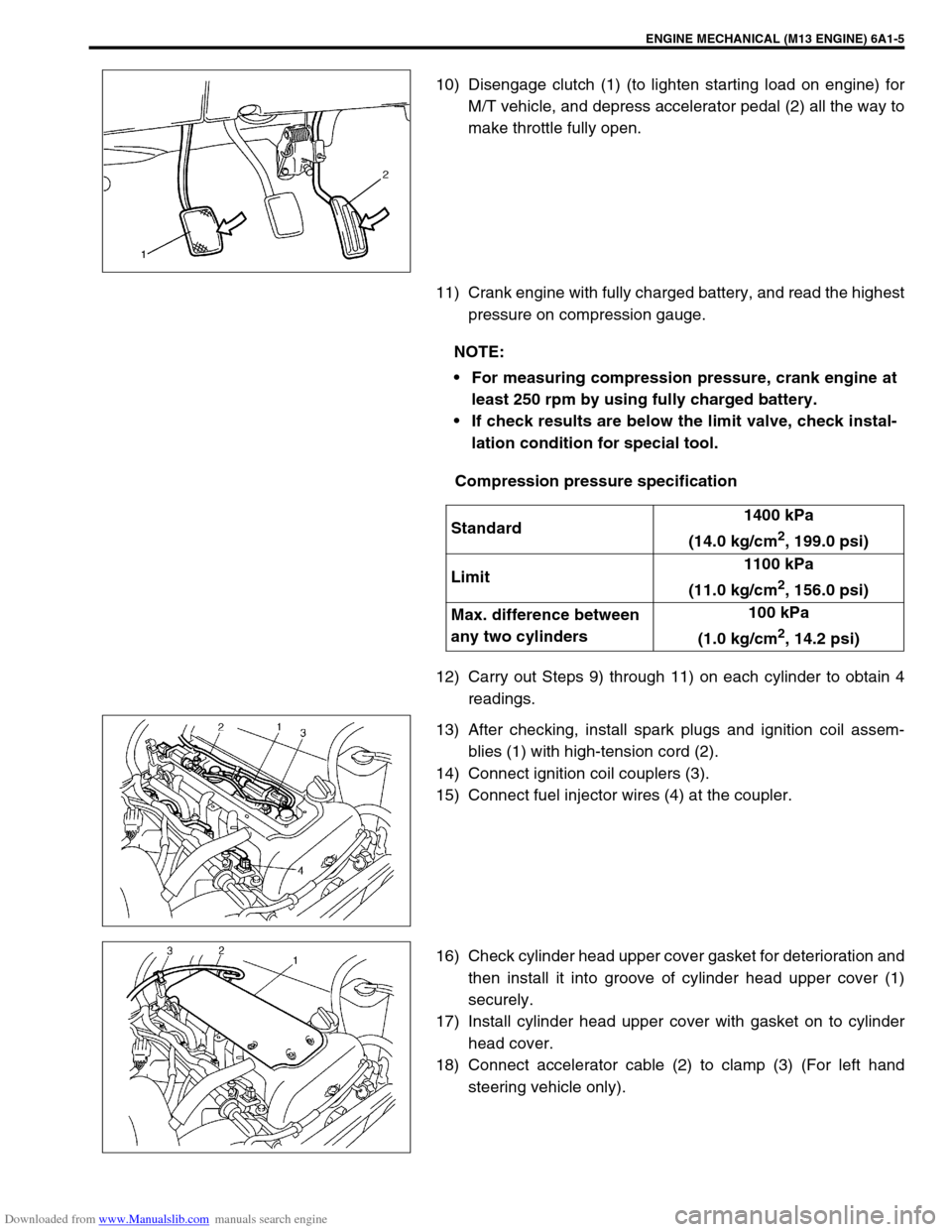
10) Disengage clutch (1) (to lighten starting load on engine) for
M/T vehicle, and depress accelerator pedal (2) all the way to
make throttle fully open.
11) Crank engine with fully charged battery, and read the highest
pressure on compression gauge.
Compression pressure specification
12) Carry out Steps 9) through 11) on each cylinder to obtain 4
readings.
13) After checking, install spark plugs and ignition coil assem-
blies (1) with high-tension cord (2).
14) Connect ignition coil couplers (3).
15) Connect fuel injector wires (4) at the coupler.
16) Check cylinder head upper cover gasket for deterioration and
then install it into groove of cylinder head upper cover (1)
securely.
17) Install cylinder head upper cover with gasket on to cylinder
head cover.
18) Connect accelerator cable (2) to clamp (3) (For left hand
steering vehicle only).
NOTE:
For measuring compression pressure, crank engine at
least 250 rpm by using fully charged battery.
If check results are below the limit valve, check instal-
lation condition for special tool.
Standard1400 kPa
(14.0 kg/cm
2, 199.0 psi)
Limit1100 kPa
(11.0 kg/cm
2, 156.0 psi)
Max. difference between
any two cylinders100 kPa
(1.0 kg/cm
2, 14.2 psi)
Page 504 of 687
Downloaded from www.Manualslib.com manuals search engine ENGINE MECHANICAL (M13 ENGINE) 6A1-23
3) Install exhaust manifold stiffener (1).
Tighten exhaust manifold stiffener bolts to specified torque.
Tightening torque
Exhaust manifold stiffener bolts
(a) : 50 N·m (5.0 kg-m, 36.5 lb-ft)
4) Install exhaust manifold cover (1).
5) Connect heated oxygen sensor coupler (2) and fit coupler to
bracket securely (if equipped).
6) Connect negative cable at battery.
7) Check exhaust system for exhaust gas leakage.
Page 507 of 687

Downloaded from www.Manualslib.com manuals search engine 6A1-26 ENGINE MECHANICAL (M13 ENGINE)
INSTALLATION
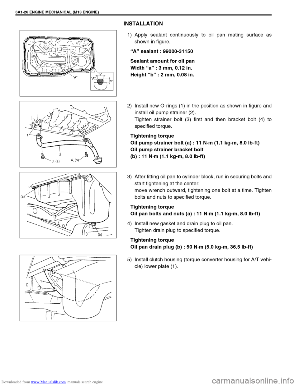
1) Apply sealant continuously to oil pan mating surface as
shown in figure.
“A” sealant : 99000-31150
Sealant amount for oil pan
Width “a” : 3 mm, 0.12 in.
Height “b” : 2 mm, 0.08 in.
2) Install new O-rings (1) in the position as shown in figure and
install oil pump strainer (2).
Tighten strainer bolt (3) first and then bracket bolt (4) to
specified torque.
Tightening torque
Oil pump strainer bolt (a) : 11 N·m (1.1 kg-m, 8.0 lb-ft)
Oil pump strainer bracket bolt
(b) : 11 N·m (1.1 kg-m, 8.0 lb-ft)
3) After fitting oil pan to cylinder block, run in securing bolts and
start tightening at the center:
move wrench outward, tightening one bolt at a time. Tighten
bolts and nuts to specified torque.
Tightening torque
Oil pan bolts and nuts (a) : 11 N·m (1.1 kg-m, 8.0 lb-ft)
4) Install new gasket and drain plug to oil pan.
Tighten drain plug to specified torque.
Tightening torque
Oil pan drain plug (b) : 50 N·m (5.0 kg-m, 36.5 lb-ft)
5) Install clutch housing (torque converter housing for A/T vehi-
cle) lower plate (1).
Page 512 of 687

Downloaded from www.Manualslib.com manuals search engine ENGINE MECHANICAL (M13 ENGINE) 6A1-31
INSPECTION
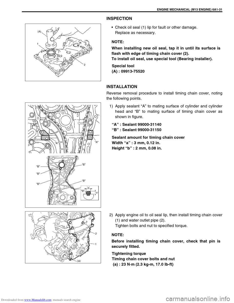
Check oil seal (1) lip for fault or other damage.
Replace as necessary.
Special tool
(A) : 09913-75520
INSTALLATION
Reverse removal procedure to install timing chain cover, noting
the following points.
1) Apply sealant “A” to mating surface of cylinder and cylinder
head and “B” to mating surface of timing chain cover as
shown in figure.
“A” : Sealant 99000-31140
“B” : Sealant 99000-31150
Sealant amount for timing chain cover
Width “a” : 3 mm, 0.12 in.
Height “b” : 2 mm, 0.08 in.
2) Apply engine oil to oil seal lip, then install timing chain cover
(1) and water outlet pipe (2).
Tighten bolts and nut to specified torque.
Tightening torque
Timing chain cover bolts and nut
(a) : 23 N·m (2.3 kg-m, 17.0 lb-ft) NOTE:
When installing new oil seal, tap it in until its surface is
flash with edge of timing chain cover (2).
To install oil seal, use special tool (Bearing installer).
NOTE:
Before installing timing chain cover, check that pin is
securely fitted.
Page 541 of 687

Downloaded from www.Manualslib.com manuals search engine 6A1-60 ENGINE MECHANICAL (M13 ENGINE)
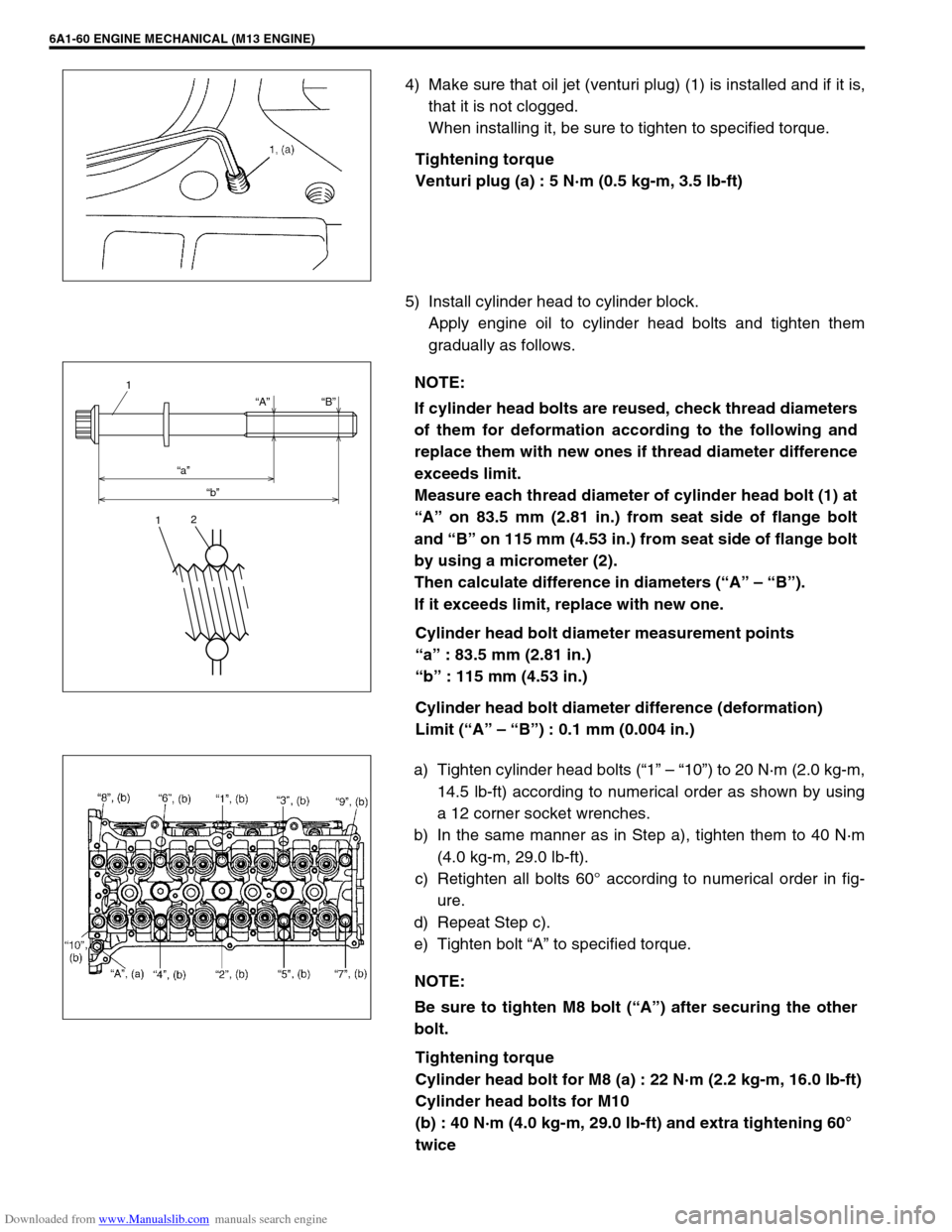
4) Make sure that oil jet (venturi plug) (1) is installed and if it is,
that it is not clogged.
When installing it, be sure to tighten to specified torque.
Tightening torque
Venturi plug (a) : 5 N·m (0.5 kg-m, 3.5 lb-ft)
5) Install cylinder head to cylinder block.
Apply engine oil to cylinder head bolts and tighten them
gradually as follows.
Cylinder head bolt diameter measurement points
“a” : 83.5 mm (2.81 in.)
“b” : 115 mm (4.53 in.)
Cylinder head bolt diameter difference (deformation)
Limit (“A” – “B”) : 0.1 mm (0.004 in.)
a) Tighten cylinder head bolts (“1” – “10”) to 20 N·m (2.0 kg-m,
14.5 lb-ft) according to numerical order as shown by using
a 12 corner socket wrenches.
b) In the same manner as in Step a), tighten them to 40 N·m
(4.0 kg-m, 29.0 lb-ft).
c) Retighten all bolts 60° according to numerical order in fig-
ure.
d) Repeat Step c).
e) Tighten bolt “A” to specified torque.
Tightening torque
Cylinder head bolt for M8 (a) : 22 N·m (2.2 kg-m, 16.0 lb-ft)
Cylinder head bolts for M10
(b) : 40 N·m (4.0 kg-m, 29.0 lb-ft) and extra tightening 60°
twice
NOTE:
If cylinder head bolts are reused, check thread diameters
of them for deformation according to the following and
replace them with new ones if thread diameter difference
exceeds limit.
Measure each thread diameter of cylinder head bolt (1) at
“A” on 83.5 mm (2.81 in.) from seat side of flange bolt
and “B” on 115 mm (4.53 in.) from seat side of flange bolt
by using a micrometer (2).
Then calculate difference in diameters (“A” – “B”).
If it exceeds limit, replace with new one.
“A”
“a”
“b”“B”
1
12
NOTE:
Be sure to tighten M8 bolt (“A”) after securing the other
bolt.
Page 542 of 687

Downloaded from www.Manualslib.com manuals search engine ENGINE MECHANICAL (M13 ENGINE) 6A1-61
6) Install exhaust manifold stiffener and exhaust pipe referring
to “Exhaust Manifold” in this section.
7) Install camshafts, timing chain and chain cover referring to
“Camshaft, Tappet and Shim”, “Timing Chain and Chain
Tensioner” and “Timing Chain Cover” in this section.
8) Install cylinder head cover and oil pan referring to “Cylinder
Head Cover” and “Oil Pan and Oil Pump Strainer” in this sec-
tion.
9) Install intake manifold stiffener and connect each hoses and
electric lead wires securely.
10) Install air cleaner outlet hoses.
11) Install radiator with cooling fan and connect A/T fluid hoses
(vehicle with A/T), radiator inlet and outlet hoses referring to
“Water Pump Belt and Cooling Fan” and “Radiator” in Sec-
tion 6B.
12) Adjust generator belt tension referring to “Water Pump Belt
Tension” in Section 6B.
13) Adjust A/C compressor and/or P/S pump belt tension (if
equipped) referring to “Compressor Drive Belt” in Section 1B
or “Power Steering Belt” in Section 3B1.
14) Adjust accelerator cable play referring to “Accelerator Cable
Adjustment” in Section 6E.
15) Check to ensure that all removed parts are back in place.
Reinstall any necessary parts which have not been rein-
stalled.
16) Refill cooling system with coolant, engine with engine oil and
A/T with specified A/T fluid (vehicle with A/T).
17) Connect negative cable at battery.
18) Verify that there is no fuel leakage, coolant leakage, oil leak-
age, A/T fluid leakage (vehicle with A/T) and exhaust gas
leakage at each connection.
Page 588 of 687
Downloaded from www.Manualslib.com manuals search engine ENGINE COOLING 6B-11
Coolant Draining
1) Remove radiator cap (1).
2) Loosen drain plug on radiator to drain coolant.
3) After draining coolant, be sure to tighten drain plug securely.
4) Fill cooling system. Refer to “Coolant” in this section.
Cooling Water Pipes or Hoses
REMOVAL
1) Drain cooling system.
2) To remove water pipes or hoses, loosen screw on each pipe
or hose clip and pull hose end off.
INSTALLATION
Install removed parts in reverse order of removal procedure, not-
ing the following.
Tighten each clamp bolt securely.
Refill cooling system with proper coolant, referring to
description on “Coolant” and “Cooling System Flush and
Refill” in this section.
Thermostat
REMOVAL
1) Drain cooling system and tighten drain plug.
2) Remove intake manifold, referring to “Throttle Body and
Intake Manifold” in Section 6A1.
3) Disconnect thermostat cap (1) from thermostat case (2).
4) Remove thermostat (3).