Page 630 of 687

Downloaded from www.Manualslib.com manuals search engine ENGINE AND EMISSION CONTROL SYSTEM 6E-25
INSTALLATION
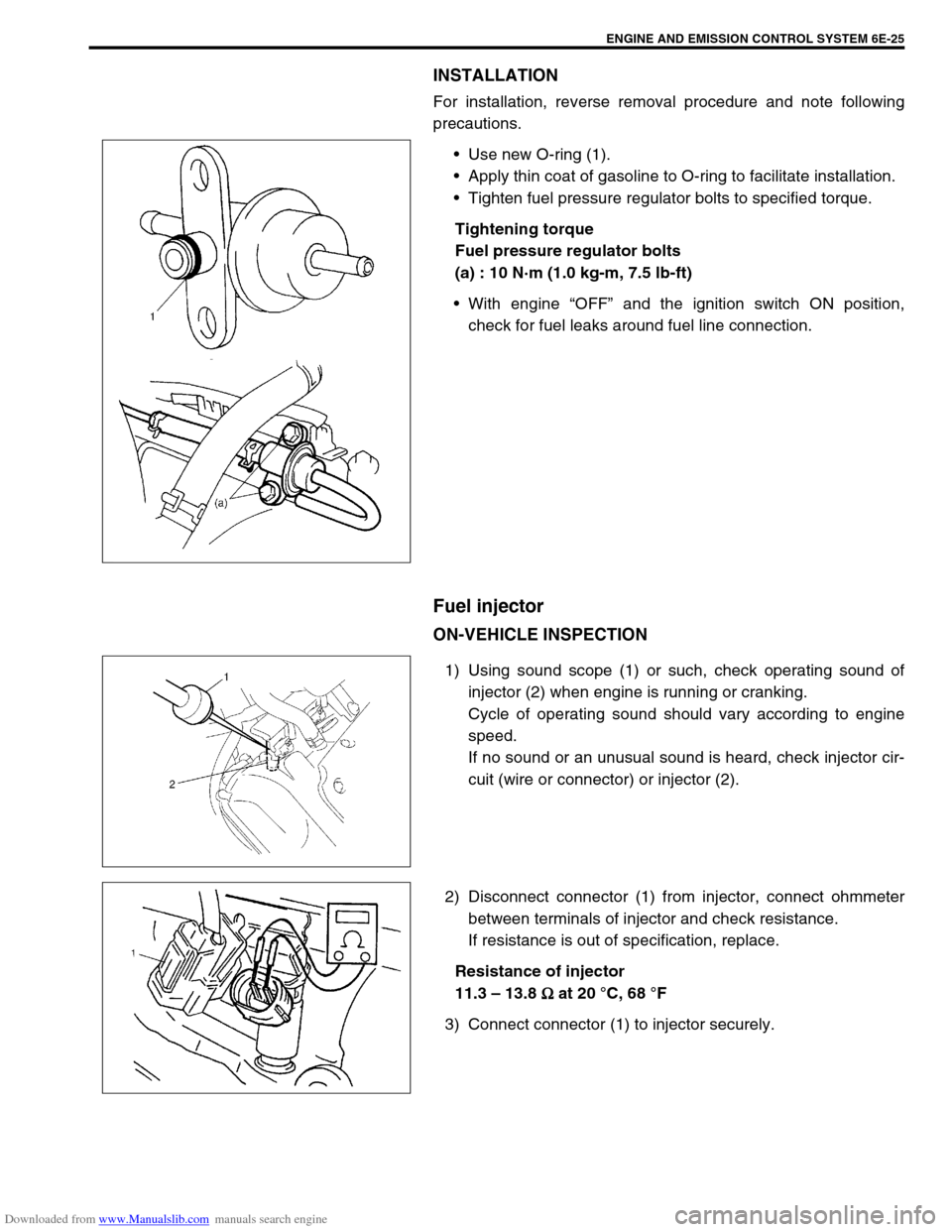
For installation, reverse removal procedure and note following
precautions.
Use new O-ring (1).
Apply thin coat of gasoline to O-ring to facilitate installation.
Tighten fuel pressure regulator bolts to specified torque.
Tightening torque
Fuel pressure regulator bolts
(a) : 10 N·m (1.0 kg-m, 7.5 lb-ft)
With engine “OFF” and the ignition switch ON position,
check for fuel leaks around fuel line connection.
Fuel injector
ON-VEHICLE INSPECTION
1) Using sound scope (1) or such, check operating sound of
injector (2) when engine is running or cranking.
Cycle of operating sound should vary according to engine
speed.
If no sound or an unusual sound is heard, check injector cir-
cuit (wire or connector) or injector (2).
2) Disconnect connector (1) from injector, connect ohmmeter
between terminals of injector and check resistance.
If resistance is out of specification, replace.
Resistance of injector
11.3 – 13.8
Ω
ΩΩ Ω at 20 °C, 68 °F
3) Connect connector (1) to injector securely.
Page 634 of 687
Downloaded from www.Manualslib.com manuals search engine ENGINE AND EMISSION CONTROL SYSTEM 6E-29
Electronic Control System
Engine control module (ECM)
REMOVAL
1) Disconnect battery negative cable at battery.
2) Disable air bag system, refer to “Disabling Air Bag System”
in Section 10B if equipped.
3) Remove glove box.
4) Disconnect ECM (1) and TCM (3) (if equipped) connectors.
5) Loosen 2 nuts (2) and remove ECM and TCM (if equipped).
INSTALLATION
1) Reverse removal procedure noting the following:
Connect connectors to ECM and TCM (if equipped)
securely.
Manifold absolute pressure sensor (MAP sensor)
INSPECTION
Check MAP sensor referring to “MAP Sensor Individual Check” in
DTC P0105 (No.11) Flow Table of Section 6. If malfunction is
found, replace.CAUTION:
As ECM consists of precision parts, be careful not to
expose it to excessive shock.
Page 635 of 687

Downloaded from www.Manualslib.com manuals search engine 6E-30 ENGINE AND EMISSION CONTROL SYSTEM
Throttle position sensor (TP sensor)
INSPECTION
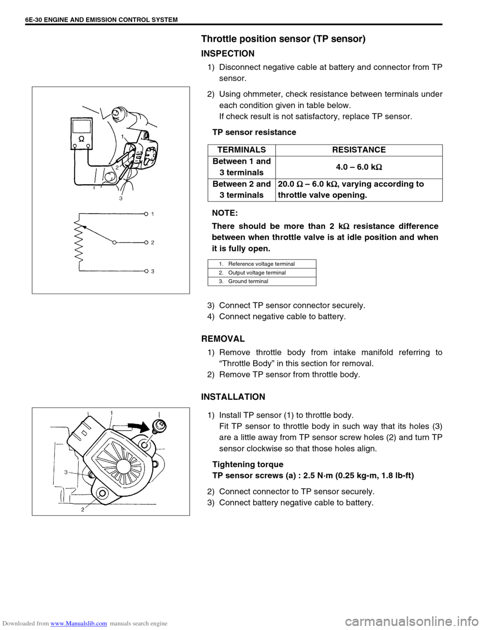
1) Disconnect negative cable at battery and connector from TP
sensor.
2) Using ohmmeter, check resistance between terminals under
each condition given in table below.
If check result is not satisfactory, replace TP sensor.
TP sensor resistance
3) Connect TP sensor connector securely.
4) Connect negative cable to battery.
REMOVAL
1) Remove throttle body from intake manifold referring to
“Throttle Body” in this section for removal.
2) Remove TP sensor from throttle body.
INSTALLATION
1) Install TP sensor (1) to throttle body.
Fit TP sensor to throttle body in such way that its holes (3)
are a little away from TP sensor screw holes (2) and turn TP
sensor clockwise so that those holes align.
Tightening torque
TP sensor screws (a) : 2.5 N·m (0.25 kg-m, 1.8 lb-ft)
2) Connect connector to TP sensor securely.
3) Connect battery negative cable to battery.TERMINALS RESISTANCE
Between 1 and
3 terminals4.0 – 6.0 k
Ω
ΩΩ Ω
Between 2 and
3 terminals20.0
Ω
ΩΩ Ω – 6.0 k
Ω
ΩΩ Ω, varying according to
throttle valve opening.
NOTE:
There should be more than 2 k
Ω
ΩΩ Ω resistance difference
between when throttle valve is at idle position and when
it is fully open.
1. Reference voltage terminal
2. Output voltage terminal
3. Ground terminal
Page 636 of 687
Downloaded from www.Manualslib.com manuals search engine ENGINE AND EMISSION CONTROL SYSTEM 6E-31
Intake air temperature sensor (IAT sensor)
REMOVAL
1) Disconnect battery negative cable at battery.
2) Disconnect connector from IAT sensor (1).
3) Remove IAT sensor (1) from air cleaner case (2).
INSPECTION
Immerse temperature sensing part of IAT sensor in water (or ice)
and measure resistance between sensor terminals while heating
water gradually.
If measured resistance doesn’t show such characteristic as
shown in left figure, replace IAT sensor.
INSTALLATION
Reverse removal procedure noting the following.
Clean mating surfaces of IAT sensor and air cleaner case.
Connect IAT sensor connector (1) securely.
Page 638 of 687

Downloaded from www.Manualslib.com manuals search engine ENGINE AND EMISSION CONTROL SYSTEM 6E-33
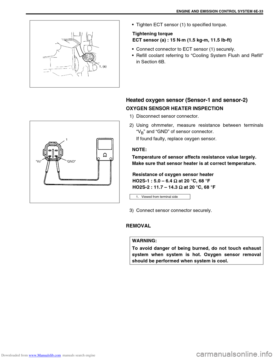
Tighten ECT sensor (1) to specified torque.
Tightening torque
ECT sensor (a) : 15 N·m (1.5 kg-m, 11.5 lb-ft)
Connect connector to ECT sensor (1) securely.
Refill coolant referring to “Cooling System Flush and Refill”
in Section 6B.
Heated oxygen sensor (Sensor-1 and sensor-2)
OXYGEN SENSOR HEATER INSPECTION
1) Disconnect sensor connector.
2) Using ohmmeter, measure resistance between terminals
“V
B” and “GND” of sensor connector.
If found faulty, replace oxygen sensor.
Resistance of oxygen sensor heater
HO2S-1 : 5.0 – 6.4
Ω
ΩΩ Ω at 20 °C, 68 °F
HO2S-2 : 11.7 – 14.3
Ω
ΩΩ Ω at 20 °C, 68 °F
3) Connect sensor connector securely.
REMOVAL
NOTE:
Temperature of sensor affects resistance value largely.
Make sure that sensor heater is at correct temperature.
1. Viewed from terminal side
WARNING:
To avoid danger of being burned, do not touch exhaust
system when system is hot. Oxygen sensor removal
should be performed when system is cool.
Page 639 of 687

Downloaded from www.Manualslib.com manuals search engine 6E-34 ENGINE AND EMISSION CONTROL SYSTEM
1) Disconnect negative cable at battery.
2) For sensor-1, remove exhaust manifold cover (1) and dis-
connect connector of heated oxygen sensor and release its
wire harness from clamps.
3) For sensor-2, disconnect connector of heated oxygen sensor
and release its wire harness from clamp. Hoist vehicle and
then remove exhaust No.1 pipe covers (3).
4) Remove heated oxygen sensor (2) from exhaust manifold or
exhaust No.1 pipe.
INSTALLATION
Reverse removal procedure noting the following.
Tighten heated oxygen sensor (2) to specified torque.
Tightening torque
Heated oxygen sensor (a) : 45 N·m (4.5 kg-m, 32.5 lb-ft)
Connect connector of heated oxygen sensor (2) and clamp
wire harness securely.
After installing heated oxygen sensor (2), start engine and
check that no exhaust gas leakage exists.
Camshaft position sensor
INSPECTION
Check camshaft position sensor referring to “DTC P0340 (No. 15)
Diag. Flow Table” in Section 6. If malfunction is found, replace.
REMOVAL
1) Disconnect negative cable at battery.
2) Disconnect connector from camshaft position sensor.
3) Remove camshaft position sensor from cylinder head.
INSTALLATION
1) Check that O-ring is free from damage.
2) Check that camshaft position sensor and signal rotor tooth
are free from any metal particles and damage.
3) Install camshaft position sensor to sensor case.
Tightening torque
Camshaft position sensor bolt
(a) : 10 N·m (1.0 kg-m, 7.5 lb-ft)
4) Connect connector to it securely.
5) Connect negative cable to battery.
[A] : HO2S-1
[B] : HO2S-2
Page 640 of 687
Downloaded from www.Manualslib.com manuals search engine ENGINE AND EMISSION CONTROL SYSTEM 6E-35
Crankshaft position sensor
INSPECTION
Check crankshaft position sensor referring to step 2 and 6 of
“DTC P0335 (No.23) Flow Table” in Section 6. If malfunction is
found, replace.
REMOVAL
1) Disconnect negative cable at battery.
2) Remove generator drive belt, loosen pivot bolt and move
generator outward.
3) Disconnect connector from crankshaft position sensor.
4) Remove crankshaft position sensor (1) from cylinder block.
INSTALLATION
1) Check to make sure that crankshaft position sensor and pul-
ley tooth is free from any metal particles and damage.
2) Install crankshaft position sensor to cylinder block.
3) Connect connector to it securely.
4) Adjust generator belt tension, refer to “Water Pump Belt Ten-
sion” in Section 6B.
5) Connect negative cable to battery.
Page 652 of 687

Downloaded from www.Manualslib.com manuals search engine IGNITION SYSTEM (ELECTRONIC IGNITION SYSTEM 6F-3
SYSTEM WIRING DIAGRAM
Diagnosis
1. Ignition switch 7. No.1 spark plug
2. Main relay 8. No.2 spark plug
3. Ignition coil assembly for No.1 and No.4 spark plugs 9. No.3 spark plug
4. Ignition coil assembly for No.2 and No.3 spark plugs 10. No.4 spark plug
5. CMP sensor 11. Sensed information (MAP sensor, ECT sensor, IAT sensor, TP sensor, Knock sensor, VSS, Park/
Neutral position signal, Electric load signal, Engine start signal, Test switch terminal)
6. CKP sensor
Condition Possible Cause Correction
Engine cranks, but will
not start or hard to
start (No spark)Blown fuse for ignition coil Replace.
Loose connection or disconnection of lead wire
or high-tension cord(s)Connect securely.
Faulty high-tension cord(s) Replace.
Faulty spark plug(s) Adjust, clean or replace.
Faulty ignition coil Replace ignition coil assembly.
Faulty CKP sensor or CKP sensor plate Clean, tighten or replace.
Faulty ECM Replace.
Poor fuel economy or
engine performanceIncorrect ignition timing Check related sensors and CKP
sensor plate.
Faulty spark plug(s) or high-tension cord(s) Adjust, clean or replace.
Faulty ignition coil assembly Replace.
Faulty CKP sensor or CKP sensor plate Clean, tighten or replace.
Faulty ECM Replace.