Page 466 of 687
![SUZUKI JIMNY 2005 3.G Service Workshop Manual Downloaded from www.Manualslib.com manuals search engine ENGINE GENERAL INFORMATION AND DIAGNOSIS 6-109
[D] Table 1 for Step 3 and 4
Table B-1 Fuel Injector Circuit Check
INSPECTION
Scan tool voltmete SUZUKI JIMNY 2005 3.G Service Workshop Manual Downloaded from www.Manualslib.com manuals search engine ENGINE GENERAL INFORMATION AND DIAGNOSIS 6-109
[D] Table 1 for Step 3 and 4
Table B-1 Fuel Injector Circuit Check
INSPECTION
Scan tool voltmete](/manual-img/20/7588/w960_7588-465.png)
Downloaded from www.Manualslib.com manuals search engine ENGINE GENERAL INFORMATION AND DIAGNOSIS 6-109
[D] Table 1 for Step 3 and 4
Table B-1 Fuel Injector Circuit Check
INSPECTION
Scan tool voltmeter
SUZUKI SCAN TOOL
DISPLAYVOLTAGE AT E17-6
Selector lever
position“P” and “N” range P/N range 10 – 14V
“R”, “D”, “2” and “L” range D range 0 – 1V
Step Action Yes No
1Was “Engine Diag. Flow Table” performed? Go to Step 2. Go to “Engine Diag. Flow
Table”.
2 Check Injector for Operating Sound.
Using sound scope, check each injector for
operating sound at engine cranking.
Do all 4 injector make operating sound?Fuel injector circuit is in
good condition.Go to Step 3.
3 Dose none of 4 injectors make operating sound
at Step 2?Go to Step 4. Check coupler connec-
tion and wire harness of
injector not making oper-
ating sound and injector
itself (Refer to Section
6E).
4 Check power circuit of injectors for open and
short.
Is it normal?Check all 4 injectors for
resistance respectively.
If resistance is OK, substi-
tute a known-good ECM
and recheck.Power circuit open or
short.
Page 480 of 687

Downloaded from www.Manualslib.com manuals search engine ENGINE GENERAL INFORMATION AND DIAGNOSIS 6-123
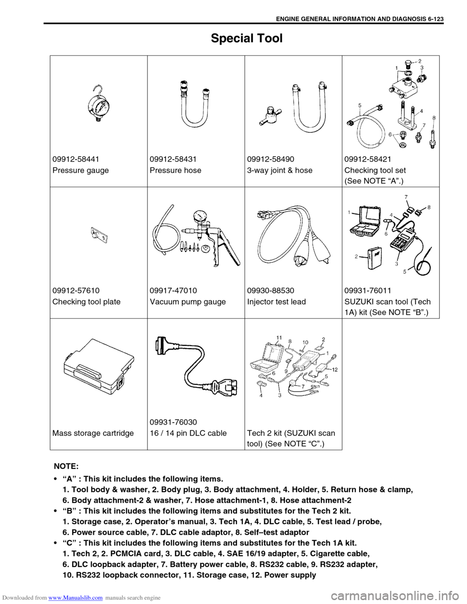
Special Tool
09912-58441 09912-58431 09912-58490 09912-58421
Pressure gauge Pressure hose 3-way joint & hose Checking tool set
(See NOTE “A”.)
09912-57610 09917-47010 09930-88530 09931-76011
Checking tool plate Vacuum pump gauge Injector test lead SUZUKI scan tool (Tech
1A) kit (See NOTE “B”.)
09931-76030
Mass storage cartridge 16 / 14 pin DLC cable Tech 2 kit (SUZUKI scan
tool) (See NOTE “C”.)
NOTE:
“A” : This kit includes the following items.
1. Tool body & washer, 2. Body plug, 3. Body attachment, 4. Holder, 5. Return hose & clamp,
6. Body attachment-2 & washer, 7. Hose attachment-1, 8. Hose attachment-2
“B” : This kit includes the following items and substitutes for the Tech 2 kit.
1. Storage case, 2. Operator’s manual, 3. Tech 1A, 4. DLC cable, 5. Test lead / probe,
6. Power source cable, 7. DLC cable adaptor, 8. Self–test adaptor
“C” : This kit includes the following items and substitutes for the Tech 1A kit.
1. Tech 2, 2. PCMCIA card, 3. DLC cable, 4. SAE 16/19 adapter, 5. Cigarette cable,
6. DLC loopback adapter, 7. Battery power cable, 8. RS232 cable, 9. RS232 adapter,
10. RS232 loopback connector, 11. Storage case, 12. Power supply
Page 485 of 687
Downloaded from www.Manualslib.com manuals search engine 6A1-4 ENGINE MECHANICAL (M13 ENGINE)
Diagnosis
Diagnosis Table
Refer to “Engine Diagnosis Table” in Section 6.
Compression Check
Check compression pressure on all 4 cylinders as follows:
1) Warm up engine.
2) Stop engine after warming up.
3) Disconnect accelerator cable (1) from clamp (2) (For left
hand steering vehicle only).
4) Remove cylinder head upper cover (3).
5) Disconnect ignition coil couplers (1).
6) Remove ignition coil assemblies (2) with high-tension cord
(3).
7) Remove all spark plugs.
8) Disconnect fuel injector wires (4) at the coupler.
9) Install special tools (Compression gauge) into spark plug
hole.
Special tool
(A) : 09915-64510-001
(B) : 09915-64510-002
(C) : 09915-64530
(D) : 09915-67010 NOTE:
After warming up engine, place transmission gear shift
lever in “Neutral” (shift selector lever to “P” range for A/T
model), and set parking brake and block drive wheels.
Page 486 of 687

Downloaded from www.Manualslib.com manuals search engine ENGINE MECHANICAL (M13 ENGINE) 6A1-5
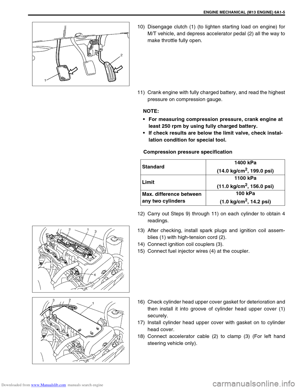
10) Disengage clutch (1) (to lighten starting load on engine) for
M/T vehicle, and depress accelerator pedal (2) all the way to
make throttle fully open.
11) Crank engine with fully charged battery, and read the highest
pressure on compression gauge.
Compression pressure specification
12) Carry out Steps 9) through 11) on each cylinder to obtain 4
readings.
13) After checking, install spark plugs and ignition coil assem-
blies (1) with high-tension cord (2).
14) Connect ignition coil couplers (3).
15) Connect fuel injector wires (4) at the coupler.
16) Check cylinder head upper cover gasket for deterioration and
then install it into groove of cylinder head upper cover (1)
securely.
17) Install cylinder head upper cover with gasket on to cylinder
head cover.
18) Connect accelerator cable (2) to clamp (3) (For left hand
steering vehicle only).
NOTE:
For measuring compression pressure, crank engine at
least 250 rpm by using fully charged battery.
If check results are below the limit valve, check instal-
lation condition for special tool.
Standard1400 kPa
(14.0 kg/cm
2, 199.0 psi)
Limit1100 kPa
(11.0 kg/cm
2, 156.0 psi)
Max. difference between
any two cylinders100 kPa
(1.0 kg/cm
2, 14.2 psi)
Page 487 of 687

Downloaded from www.Manualslib.com manuals search engine 6A1-6 ENGINE MECHANICAL (M13 ENGINE)
Engine Vacuum Check
The engine vacuum that develops in the intake line is a good indi-
cator of the condition of the engine. The vacuum checking proce-
dure is as follows:
1) Warm up engine to normal operating temperature.
2) Stop engine and turn off the all electric switches.
3) Remove cap (1) from intake manifold.
4) Connect special tool (Vacuum gauge) to intake manifold.
Special tool
(A) : 09915-67310
5) Run engine at specified idle speed and read vacuum gauge.
Vacuum should be within specification.
Vacuum specification (at sea level)
59 – 73 kPa (45 – 55 cm Hg, 17.7 – 21.6 in. Hg)
at specified idle speed
6) After checking, disconnect special tool (Vacuum gauge) from
intake manifold.
7) Install cap to intake manifold.NOTE:
After warming up engine, be sure to place transmission
gear shift lever in “Neutral” (shift selector lever to “P”
range for A/T model), and set parking brake and block
drive wheels.
Page 488 of 687

Downloaded from www.Manualslib.com manuals search engine ENGINE MECHANICAL (M13 ENGINE) 6A1-7
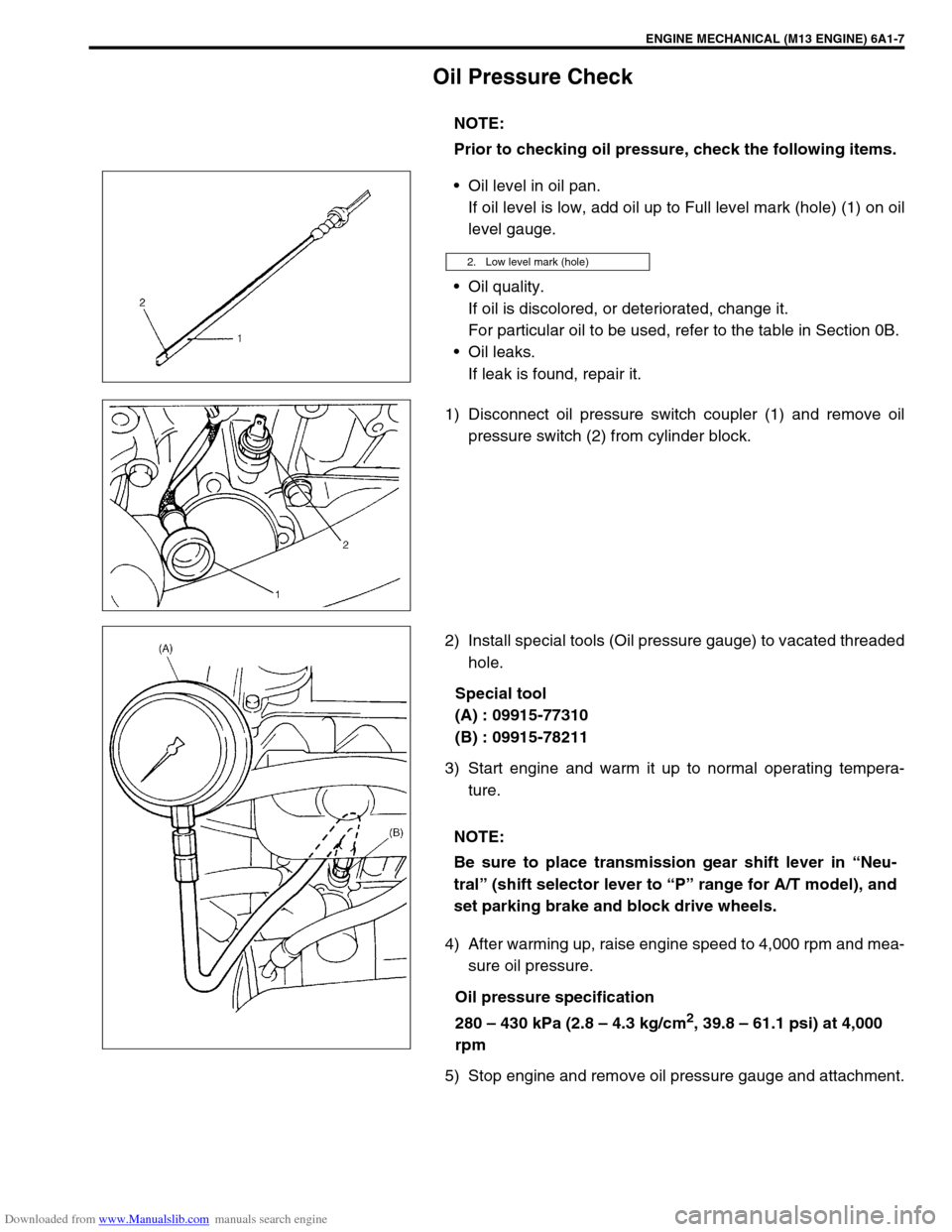
Oil Pressure Check
Oil level in oil pan.
If oil level is low, add oil up to Full level mark (hole) (1) on oil
level gauge.
Oil quality.
If oil is discolored, or deteriorated, change it.
For particular oil to be used, refer to the table in Section 0B.
Oil leaks.
If leak is found, repair it.
1) Disconnect oil pressure switch coupler (1) and remove oil
pressure switch (2) from cylinder block.
2) Install special tools (Oil pressure gauge) to vacated threaded
hole.
Special tool
(A) : 09915-77310
(B) : 09915-78211
3) Start engine and warm it up to normal operating tempera-
ture.
4) After warming up, raise engine speed to 4,000 rpm and mea-
sure oil pressure.
Oil pressure specification
280 – 430 kPa (2.8 – 4.3 kg/cm
2, 39.8 – 61.1 psi) at 4,000
rpm
5) Stop engine and remove oil pressure gauge and attachment.NOTE:
Prior to checking oil pressure, check the following items.
2. Low level mark (hole)
NOTE:
Be sure to place transmission gear shift lever in “Neu-
tral” (shift selector lever to “P” range for A/T model), and
set parking brake and block drive wheels.
Page 494 of 687
Downloaded from www.Manualslib.com manuals search engine ENGINE MECHANICAL (M13 ENGINE) 6A1-13
On-Vehicle Service
Air Cleaner Element
REMOVAL
1) Open air cleaner case by unhooking its clamps.
2) Remove air cleaner element from case.
INSPECTION
Check air cleaner element for dirt. Replace excessively dirty ele-
ment.
CLEANING
Blow off dust by compressed air from air outlet side of element.
INSTALLATION
Reverse removal procedure for installation.
Page 525 of 687

Downloaded from www.Manualslib.com manuals search engine 6A1-44 ENGINE MECHANICAL (M13 ENGINE)
Check clearance by using gauging plastic. Checking procedure is
as follows.
1) Clean housings and camshaft journals.
2) Remove all tappets with shims.
3) Install camshafts to cylinder head.
4) Place a piece of gauging plastic to full width of journal of
camshaft (parallel to camshaft).
5) Install camshaft housing.
6) Tighten camshaft housing bolts in such order as indicated in
figure a little at a time till they are tightened to specified
torque.
Tightening torque
Camshaft housing bolts (a) : 11 N·m (1.1 kg-m, 8.0 lb-ft)
7) Remove housing, and using scale (2) on gauging plastic (1)
envelop, measure gauging plastic width at its widest point.
Camshaft journal clearance
If measured camshaft journal clearance exceeds limit, measure
journal (housing) bore and outside diameter of camshaft journal.
Replace camshaft or cylinder head assembly whichever the dif-
ference from specification is greater.
Camshaft journal outside diameter [A]
Camshaft journal bore diameter [B] NOTE:
Do not rotate camshaft while gauging plastic is installed.
Standard Limit
0.045 – 0.087 mm
(0.0018 – 0.0034 in.)0.12 mm
(0.0047 in.)
Item Standard
No.126.934 – 26.955 mm
(1.0604 – 1.0612 in.)
Other22.934 – 22.955 mm
(0.9029 – 0.9037 in.)
Item Standard
No.127.000 – 27.021 mm
(1.0630 – 1.0638 in.)
Other23.000 – 23.021 mm
(0.9055 – 0.9063 in.)