Page 293 of 687
Downloaded from www.Manualslib.com manuals search engine 5-32 BRAKES
Brake shoe
REMOVAL
1) Remove brake drum referring to “Brake Drum” in this sec-
tion.
2) Remove shoe return spring lower (3), spring and rod assem-
bly (4) and shoe hold down springs (2) by turning shoe hold
down pins (1).
3) Remove parking brake shoe lever (5) from brake back plate.
INSPECT
Inspect lever for free movement against brake shoe web. If
defective, correct or replace.
Inspect ratchet or thread rod part for wear, sticking and cor-
rosion.
Inspect for damage or weakening.
Inspect each part with arrow for rust. If found defective,
replace.
INSTALLATION
Assemble parts as shown in reverse order of removal.
1) Apply rubber grease to brake back plate and parking brake
shoe lever as shown in the figure. WARNING:
Use special care when installing brake shoe return
spring. Failure in its proper installation may allow it to
spring back and cause personal injury.
1. Apply rubber grease
Page 294 of 687
Downloaded from www.Manualslib.com manuals search engine BRAKES 5-33
2) Install shoe hold down springs (2) by pushing them down in
place and turning hold down pins (1).
3) Install shoe return spring and parking brake shoe lever
spring.
4) For procedure hereafter, refer to “Brake Drum” in this sec-
tion.
Wheel Cylinder
REMOVAL
1) Remove brake drum referring to “Brake Drum” in this sec-
tion.
2) Remove brake shoe referring to “Brake Shoe” in this section.
3) Loosen brake pipe flare nut (or nuts) but only within the
extent that fluid does not leak.
4) Remove wheel cylinder mounting bolts. Disconnect brake
pipe (or pipes) from wheel cylinder and put wheel cylinder
breather plug cap (1) onto pipe to prevent fluid from spilling.
INSPECTION
Inspect wheel cylinder disassembled parts for wear, cracks, cor-
rosion or damage.
3. Shoe return spring lower
4. Spring and rod assembly
5. Adjuster lever
6. Adjuster spring
NOTE:
Clean wheel cylinder components with brake fluid.
Page 295 of 687

Downloaded from www.Manualslib.com manuals search engine 5-34 BRAKES
INSTALLATION
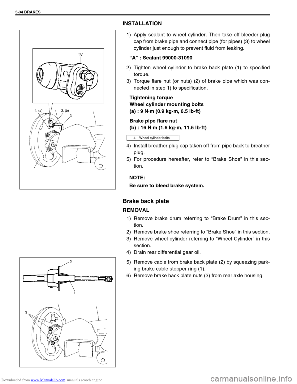
1) Apply sealant to wheel cylinder. Then take off bleeder plug
cap from brake pipe and connect pipe (for pipes) (3) to wheel
cylinder just enough to prevent fluid from leaking.
“A” : Sealant 99000-31090
2) Tighten wheel cylinder to brake back plate (1) to specified
torque.
3) Torque flare nut (or nuts) (2) of brake pipe which was con-
nected in step 1) to specification.
Tightening torque
Wheel cylinder mounting bolts
(a) : 9 N·m (0.9 kg-m, 6.5 lb-ft)
Brake pipe flare nut
(b) : 16 N·m (1.6 kg-m, 11.5 lb-ft)
4) Install breather plug cap taken off from pipe back to breather
plug.
5) For procedure hereafter, refer to “Brake Shoe” in this sec-
tion.
Brake back plate
REMOVAL
1) Remove brake drum referring to “Brake Drum” in this sec-
tion.
2) Remove brake shoe referring to “Brake Shoe” in this section.
3) Remove wheel cylinder referring to “Wheel Cylinder” in this
section.
4) Drain rear differential gear oil.
5) Remove cable from brake back plate (2) by squeezing park-
ing brake cable stopper ring (1).
6) Remove brake back plate nuts (3) from rear axle housing.
4. Wheel cylinder bolts
NOTE:
Be sure to bleed brake system.
Page 313 of 687

Downloaded from www.Manualslib.com manuals search engine 5-52 BRAKES
Parking Brake Lever/Cable
Parking brake lever
REMOVAL
1) Hoist vehicle and release parking brake lever.
2) Disconnect negative cable at battery.
3) Remove parking brake lever cover.
4) Disconnect lead wire of parking brake switch at coupler.
5) Remove adjusting nut.
6) Loosen bracket nut (3) and disconnect parking brake cables
(2) from equalizer (4).
7) Remove parking brake lever bolts and then remove parking
brake lever assembly (1).
INSTALLATION
1) Install in reverse order of REMOVAL procedure.
Equalizer angle “a” : within 15 degrees
Tightening torque
Parking brake lever bolts
(a) : 23 N·m (2.3 kg-m, 17.0 lb-ft)
2) After all parts are installed, parking brake lever needs to be
adjusted. Refer to “Parking Brake Inspection and Adjust-
ment” in this section.
3) Check brake drum for dragging and brake system for proper
performance. NOTE:
Don’t disassemble parking brake lever switch. It must be
removed and installed as a complete switch assembly.
1. Parking brake lever
2. Parking brake cable
3. Adjusting nut
4. Equalizer
Page 314 of 687
Downloaded from www.Manualslib.com manuals search engine BRAKES 5-53
Parking Brake Cable
REMOVAL
1) Raise, suitably support vehicle and remove wheel if necessary.
2) Remove parking brake cable.
INSTALLATION
1) Install it by reversing removal procedure, noting the following points.
Install clamps properly referring to figure below.
Tighten bolts and nuts to specified torque.
2) Upon completion of installation, adjust cable. (Refer to “Parking Brake Inspection and Adjustment” in this
section.) Then check brake drum for dragging and brake system for proper performance. After removing
vehicle from hoist, brake test should be performed.
E : View E J : View J 2. Floor Tightening torque
G : View G K : View K 3. Cross member
H : View H 1. Bracket 4. Clamp
Page 315 of 687

Downloaded from www.Manualslib.com manuals search engine 5-54 BRAKES
Tightening Torque Specifications
Required Service Material
Fastening partTightening torque
Nm kg-m lb-ft
Brake caliper carrier bolt 85 8.5 61.5
Brake caliper pin bolt 22 2.2 16.0
Front brake flexible hose bolt 23 2.3 17.0
Rear brake back plate nut 23 2.3 17.0
Master cylinder nut 13 1.3 9.5
Booster nut 13 1.3 9.5
Brake pipe 5-way 4-way joint bolt 11 1.1 8.0
Brake pipe flare nut 16 1.6 12.0
LSPV bolt/P valve bolt 25 2.5 18.0
Brake bleeder plugFront caliper 11 1.1 8.0
Rear wheel cylinder, LSPV 8 0.8 6.0
Wheel nut 95 9.5 69.0
Hose bracket bolt 11 1.1 8.0
Booster clevis nut 25 2.5 18.0
Stop light switch lock nut 6.5 0.65 4.7
Parking brake lever bolt 23 2.3 17.0
Wheel cylinder mounting bolt 9 0.9 6.5
Piston stopper bolt 10 1.0 7.5
LSPV adjust bolt 25 2.5 18.0
Material Recommended SUZUKI products Use
Brake fluid Indicated on reservoir tank cap or
described in owner’s manual of vehi-
cleTo fill master cylinder reservoir.
To clean and apply to inner parts of master
cylinder caliper and wheel cylinder when they
are disassembled.
Water tight sealant SEALING COMPOUND 366E
99000-31090To apply to mating surfaces of brake back
plate and rear wheel cylinder.
Sealant SUZUKI BOND NO. 1215
99000-31110To apply to mating surfaces of brake back
plate and rear axle housing.
To apply to mating surfaces of brake back
plate and rear wheel bearing retainer.
Page 319 of 687

Downloaded from www.Manualslib.com manuals search engine 5E-2 ANTILOCK BRAKE SYSTEM (ABS)
General Description
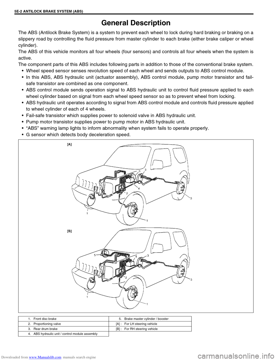
The ABS (Antilock Brake System) is a system to prevent each wheel to lock during hard braking or braking on a
slippery road by controlling the fluid pressure from master cylinder to each brake (either brake caliper or wheel
cylinder).
The ABS of this vehicle monitors all four wheels (four sensors) and controls all four wheels when the system is
active.
The component parts of this ABS includes following parts in addition to those of the conventional brake system.
Wheel speed sensor senses revolution speed of each wheel and sends outputs to ABS control module.
In this ABS, ABS hydraulic unit (actuator assembly), ABS control module, pump motor transistor and fail-
safe transistor are combined as one component.
ABS control module sends operation signal to ABS hydraulic unit to control fluid pressure applied to each
wheel cylinder based on signal from each wheel speed sensor so as to prevent wheel from locking.
ABS hydraulic unit operates according to signal from ABS control module and controls fluid pressure applied
to wheel cylinder of each of 4 wheels.
Fail-safe transistor which supplies power to solenoid valve in ABS hydraulic unit.
Pump motor transistor supplies power to pump motor in ABS hydraulic unit.
“ABS” warning lamp lights to inform abnormality when system fails to operate properly.
G sensor which detects body deceleration speed.
1. Front disc brake 5. Brake master cylinder / booster
2. Proportioning valve [A] : For LH steering vehicle
3. Rear drum brake [B] : For RH steering vehicle
4. ABS hydraulic unit / control module assembly
Page 323 of 687

Downloaded from www.Manualslib.com manuals search engine 5E-6 ANTILOCK BRAKE SYSTEM (ABS)
Diagnosis
To ensure that the trouble diagnosis is done accurately and smoothly, observe “Precautions in Diagnosing Trou-
bles” and follow “ABS Diagnostic Flow Table”.
Precaution in Diagnosing Troubles
If the vehicles was operated in any of the following ways, “ABS” warning lamp may light momentarily but this
does not indicate anything abnormal in ABS.
–The vehicle was driven with parking brake pulled.
–The vehicle was driven with brake dragging.
–The vehicle was stuck in mud, sand, etc.
–Wheel spin occurred while driving.
–Wheel(s) was rotated while the vehicle was jacked up.
Be sure to read “Precautions for Electronic Circuit Service” in Section 0A before inspection and observe
what is written there.
Be sure to use the trouble diagnosis procedure as described in the flow table. Failure to follow the flow table
may result in incorrect diagnosis. Some other diag. trouble code may be stored by mistake in the memory of
ABS control module during inspection.
ABS Diagnostic Flow Table
Refer to the following for the details of each step.
Step Action Yes No
1 Perform customer complaint analysis, problem symptom confir-
mation and diagnostic trouble code check record and clear-
ance.
Is there any trouble code?Go to Step 2. Go to Step 5.
2 Perform driving test.
Is trouble symptom identified?Go to Step 3. Go to Step 6.
3 Check diagnostic trouble code.
Is it malfunction code?Go to Step 4. Go to Step 5.
4 Inspect and repair referring to applicable diagnostic trouble
code table in this section. Then perform final confirmation test
after clearing diagnostic trouble code.
Is trouble recur?Go to Step 7. End.
5 Inspect and repair referring to “Diagnosis Table” in Section 5.
Then perform final confirmation test after clearing diagnostic
trouble code.
Is trouble recur?Go to Step 7. End.
6 Check for intermittent problems referring to “Intermittent and
Poor Connection” in Section 0A and related circuit of trouble
code recorded in Step 3. Then perform final confirmation test
after clearing diagnostic trouble code.
Is trouble recur?Go to Step 7. End.
7 Perform diagnostic trouble code check record and clearance.
Is there any trouble code?Go to Step 4. Go to Step 5.