2005 SUZUKI JIMNY king
[x] Cancel search: kingPage 535 of 687
Downloaded from www.Manualslib.com manuals search engine 6A1-54 ENGINE MECHANICAL (M13 ENGINE)
Valves
Remove all carbon from valves.
Inspect each valve for wear, burn or distortion at its face and
stem end, as necessary, replace it.
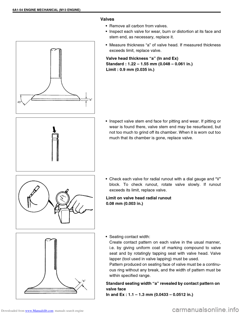
Measure thickness “a” of valve head. If measured thickness
exceeds limit, replace valve.
Valve head thickness “a” (In and Ex)
Standard : 1.22 – 1.55 mm (0.048 – 0.061 in.)
Limit : 0.9 mm (0.035 in.)
Inspect valve stem end face for pitting and wear. If pitting or
wear is found there, valve stem end may be resurfaced, but
not too much to grind off its chamber. When it is worn out too
much that its chamber is gone, replace valve.
Check each valve for radial runout with a dial gauge and “V”
block. To check runout, rotate valve slowly. If runout
exceeds its limit, replace valve.
Limit on valve head radial runout
0.08 mm (0.003 in.)
Seating contact width:
Create contact pattern on each valve in the usual manner,
i.e. by giving uniform coat of marking compound to valve
seat and by rotatingly tapping seat with valve head. Valve
lapper (tool used in valve lapping) must be used.
Pattern produced on seating face of valve must be a continu-
ous ring without any break, and the width of pattern must be
within specified range.
Standard seating width “a” revealed by contact pattern on
valve face
In and Ex : 1.1 – 1.3 mm (0.0433 – 0.0512 in.)
Page 536 of 687
Downloaded from www.Manualslib.com manuals search engine ENGINE MECHANICAL (M13 ENGINE) 6A1-55
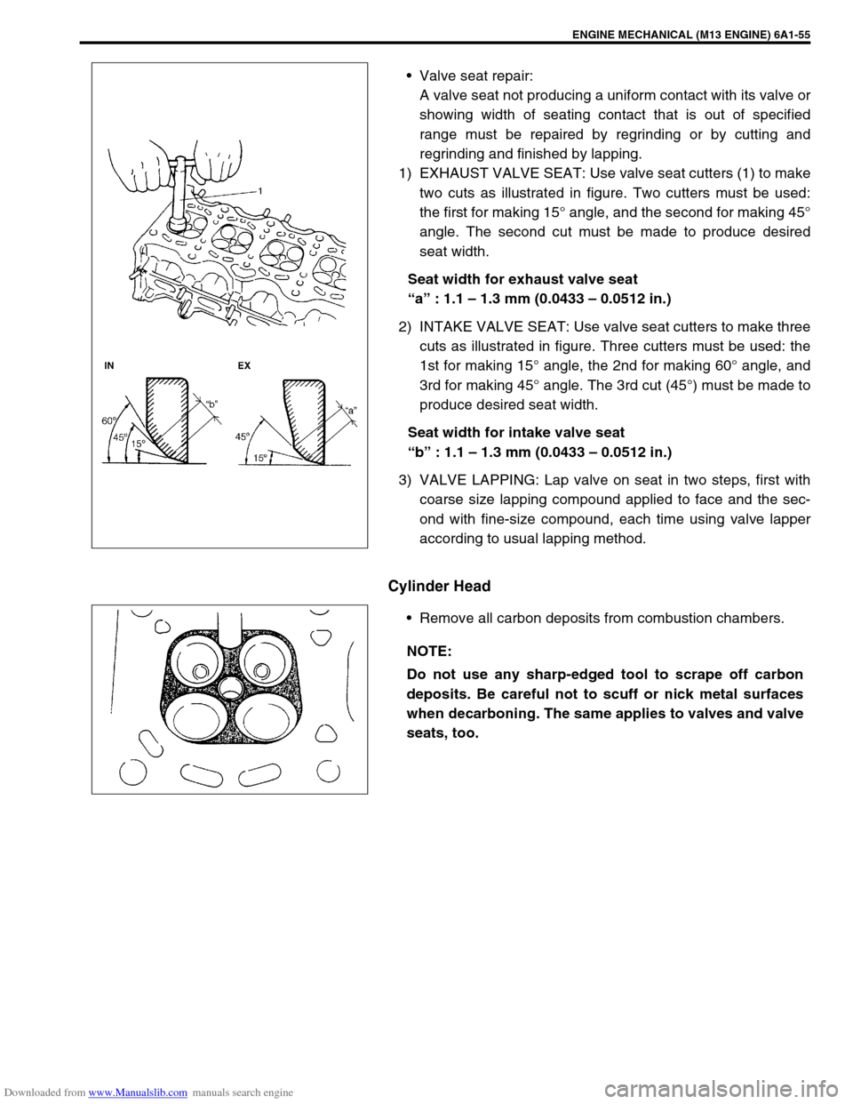
Valve seat repair:
A valve seat not producing a uniform contact with its valve or
showing width of seating contact that is out of specified
range must be repaired by regrinding or by cutting and
regrinding and finished by lapping.
1) EXHAUST VALVE SEAT: Use valve seat cutters (1) to make
two cuts as illustrated in figure. Two cutters must be used:
the first for making 15° angle, and the second for making 45°
angle. The second cut must be made to produce desired
seat width.
Seat width for exhaust valve seat
“a” : 1.1 – 1.3 mm (0.0433 – 0.0512 in.)
2) INTAKE VALVE SEAT: Use valve seat cutters to make three
cuts as illustrated in figure. Three cutters must be used: the
1st for making 15° angle, the 2nd for making 60° angle, and
3rd for making 45° angle. The 3rd cut (45°) must be made to
produce desired seat width.
Seat width for intake valve seat
“b” : 1.1 – 1.3 mm (0.0433 – 0.0512 in.)
3) VALVE LAPPING: Lap valve on seat in two steps, first with
coarse size lapping compound applied to face and the sec-
ond with fine-size compound, each time using valve lapper
according to usual lapping method.
Cylinder Head
Remove all carbon deposits from combustion chambers.
NOTE:
Do not use any sharp-edged tool to scrape off carbon
deposits. Be careful not to scuff or nick metal surfaces
when decarboning. The same applies to valves and valve
seats, too.
Page 546 of 687

Downloaded from www.Manualslib.com manuals search engine ENGINE MECHANICAL (M13 ENGINE) 6A1-65
Piston clearance:
Measure cylinder bore diameter and piston diameter to find
their difference which is piston clearance. Piston clearance
should be within specification as given below. If it is out of
specification, rebore cylinder and use oversize piston.
Piston clearance
Standard : 0.032 – 0.061 mm (0.0013 – 0.0024 in.)
Limit : 0.161 mm (0.0063 in.)
Ring groove clearance:
Before checking, piston grooves must be clean, dry and free
of carbon deposits.
Fit new piston ring (1) into piston groove, and measure clear-
ance between ring and ring land by using thickness gauge
(2).
If clearance is out of limit, replace piston.
Ring groove clearance
Top ring
Standard : 0.03 – 0.07 mm (0.0012 – 0.0028 in.)
Limit : 0.12 mm (0.0047 in.)
2nd ring
Standard : 0.02 – 0.06 mm (0.0008 – 0.0024 in.)
Limit : 0.10 mm (0.0039 in.)
Oil ring
Standard : 0.03 – 0.17 mm (0.0012 – 0.0067 in.)
Piston Pin
Check piston pin, connecting rod small end bore and piston
bore for wear or damage, paying particular attention to con-
dition of small end bore bush. If pin, connecting rod small
end bore or piston bore is badly worn or damaged, replace
pin, connecting rod and/or piston. NOTE:
Cylinder bore diameters used here are measured in
thrust direction at two positions.
“a” : 19.5 mm (0.77 in.)
Page 549 of 687
Downloaded from www.Manualslib.com manuals search engine 6A1-68 ENGINE MECHANICAL (M13 ENGINE)
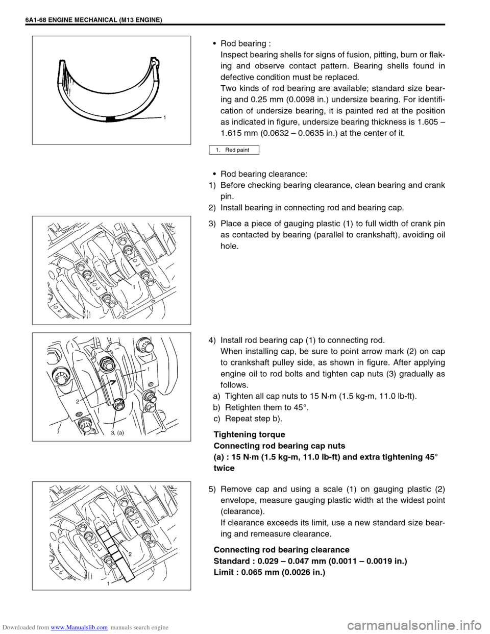
Rod bearing :
Inspect bearing shells for signs of fusion, pitting, burn or flak-
ing and observe contact pattern. Bearing shells found in
defective condition must be replaced.
Two kinds of rod bearing are available; standard size bear-
ing and 0.25 mm (0.0098 in.) undersize bearing. For identifi-
cation of undersize bearing, it is painted red at the position
as indicated in figure, undersize bearing thickness is 1.605 –
1.615 mm (0.0632 – 0.0635 in.) at the center of it.
Rod bearing clearance:
1) Before checking bearing clearance, clean bearing and crank
pin.
2) Install bearing in connecting rod and bearing cap.
3) Place a piece of gauging plastic (1) to full width of crank pin
as contacted by bearing (parallel to crankshaft), avoiding oil
hole.
4) Install rod bearing cap (1) to connecting rod.
When installing cap, be sure to point arrow mark (2) on cap
to crankshaft pulley side, as shown in figure. After applying
engine oil to rod bolts and tighten cap nuts (3) gradually as
follows.
a) Tighten all cap nuts to 15 N·m (1.5 kg-m, 11.0 lb-ft).
b) Retighten them to 45°.
c) Repeat step b).
Tightening torque
Connecting rod bearing cap nuts
(a) : 15 N·m (1.5 kg-m, 11.0 lb-ft) and extra tightening 45°
twice
5) Remove cap and using a scale (1) on gauging plastic (2)
envelope, measure gauging plastic width at the widest point
(clearance).
If clearance exceeds its limit, use a new standard size bear-
ing and remeasure clearance.
Connecting rod bearing clearance
Standard : 0.029 – 0.047 mm (0.0011 – 0.0019 in.)
Limit : 0.065 mm (0.0026 in.)
1. Red paint
Page 550 of 687

Downloaded from www.Manualslib.com manuals search engine ENGINE MECHANICAL (M13 ENGINE) 6A1-69
6) If clearance can not be brought to within its limit even by
using a new standard size bearing, regrind crankpin to
undersize and use 0.25 mm undersize bearing.
ASSEMBLY
1) Install piston pin to piston (1) and connecting rod (2):
a) After applying engine oil to piston pin and piston pin holes
in piston and connecting rod.
b) Fit connecting rod as shown in figure.
c) Insert piston pin to piston and connecting rod.
d) Install piston pin circlips (3).
2) Install piston rings to piston :
a) As indicated in figure, 1st and 2nd rings have “T” mark
respectively. When installing these piston rings to piston,
direct marked side of each ring toward top of piston.
b) 1st ring (1) differs from 2nd ring (2) in thickness, shape and
color of surface contacting cylinder wall.
Distinguish 1st ring from 2nd ring by referring to figure.
c) When installing oil ring (3) install spacer first and then two
rails.
3) After installing three rings (1st, 2nd and oil rings), distribute
their end gaps as shown in figure. NOTE:
After checking the rod bearing clearance, make sure to
check connecting rod bolt diameter.
Refer to “Inspection” of “Connecting Rod”.
NOTE:
Circlip should be installed with its cut part facing as
shown in figure. Install so that circlip end gap comes
within such range as indicated by arrow.
1. Arrow mark
2. 1st ring end gap
3. 2nd ring end gap and oil ring spacer gap
4. Oil ring upper rail gap
5. Oil ring lower rail gap
Page 563 of 687
Downloaded from www.Manualslib.com manuals search engine 6A1-82 ENGINE MECHANICAL (M13 ENGINE)
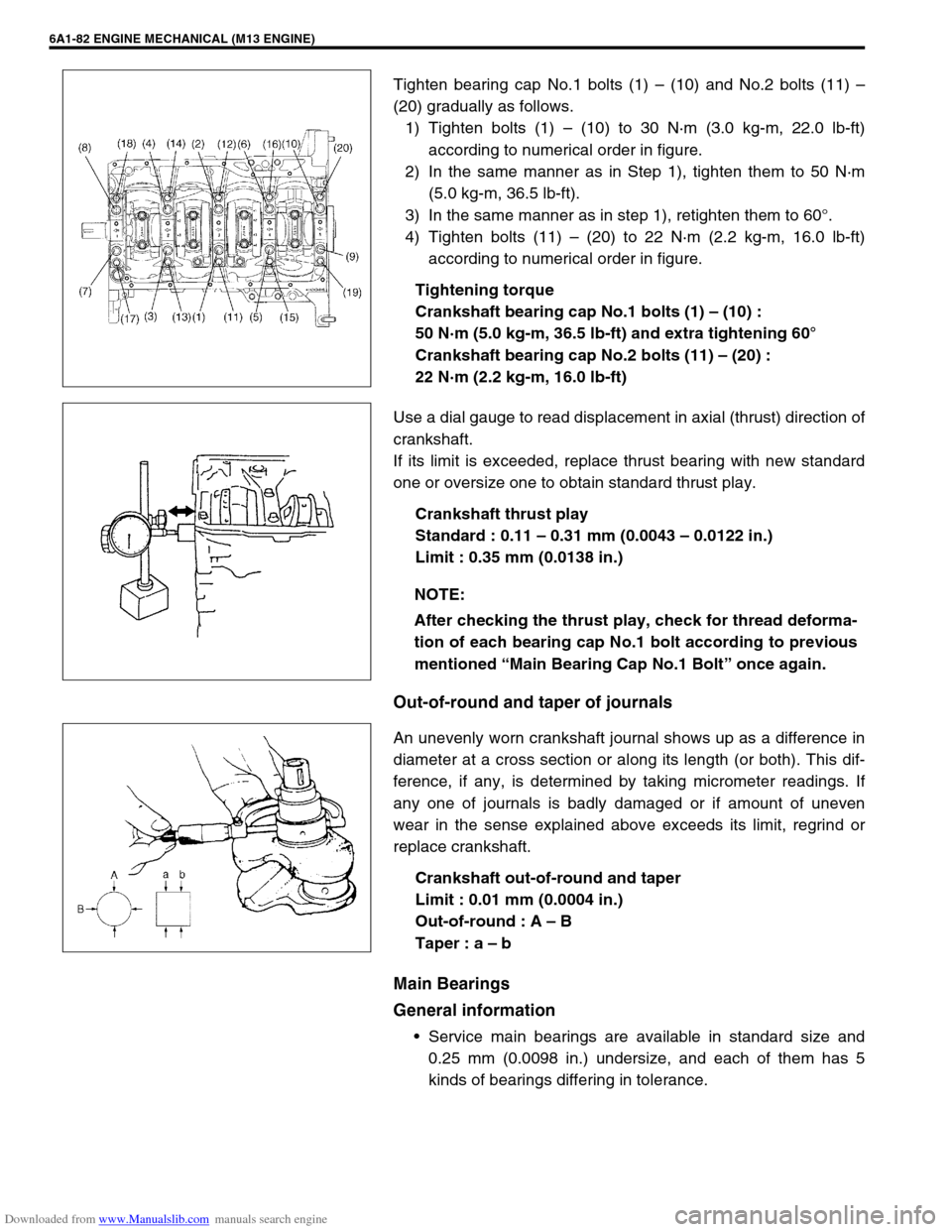
Tighten bearing cap No.1 bolts (1) – (10) and No.2 bolts (11) –
(20) gradually as follows.
1) Tighten bolts (1) – (10) to 30 N·m (3.0 kg-m, 22.0 lb-ft)
according to numerical order in figure.
2) In the same manner as in Step 1), tighten them to 50 N·m
(5.0 kg-m, 36.5 lb-ft).
3) In the same manner as in step 1), retighten them to 60°.
4) Tighten bolts (11) – (20) to 22 N·m (2.2 kg-m, 16.0 lb-ft)
according to numerical order in figure.
Tightening torque
Crankshaft bearing cap No.1 bolts (1) – (10) :
50 N·m (5.0 kg-m, 36.5 lb-ft) and extra tightening 60°
Crankshaft bearing cap No.2 bolts (11) – (20) :
22 N·m (2.2 kg-m, 16.0 lb-ft)
Use a dial gauge to read displacement in axial (thrust) direction of
crankshaft.
If its limit is exceeded, replace thrust bearing with new standard
one or oversize one to obtain standard thrust play.
Crankshaft thrust play
Standard : 0.11 – 0.31 mm (0.0043 – 0.0122 in.)
Limit : 0.35 mm (0.0138 in.)
Out-of-round and taper of journals
An unevenly worn crankshaft journal shows up as a difference in
diameter at a cross section or along its length (or both). This dif-
ference, if any, is determined by taking micrometer readings. If
any one of journals is badly damaged or if amount of uneven
wear in the sense explained above exceeds its limit, regrind or
replace crankshaft.
Crankshaft out-of-round and taper
Limit : 0.01 mm (0.0004 in.)
Out-of-round : A – B
Taper : a – b
Main Bearings
General information
Service main bearings are available in standard size and
0.25 mm (0.0098 in.) undersize, and each of them has 5
kinds of bearings differing in tolerance.
NOTE:
After checking the thrust play, check for thread deforma-
tion of each bearing cap No.1 bolt according to previous
mentioned “Main Bearing Cap No.1 Bolt” once again.
Page 565 of 687

Downloaded from www.Manualslib.com manuals search engine 6A1-84 ENGINE MECHANICAL (M13 ENGINE)
5) Remove bearing caps and using scale (1) on gauging plastic
(2) envelop, measure gauging plastic width at its widest
point. If clearance exceeds its limit, replace bearing. Always
replace both upper and lower inserts as a unit.
A new standard bearing may produce proper clearance. If
not, it will be necessary to regrind crankshaft journal for use
of 0.25 mm undersize bearing.
After selecting new bearing, recheck clearance.
Main bearing clearance
Standard : 0.025 – 0.045 mm (0.0010 – 0.0018 in.)
Limit : 0.065 mm (0.0026 in.)
Selection of main bearings
STANDARD BEARING:
If bearing is in malcondition, or bearing clearance is out of specifi-
cation, select a new standard bearing according to the following
procedure and install it.
1) First check journal diameter. As shown in figure, crank web
No.2 has stamped numbers.
Three kinds of numbers (“1”, “2” and “3”) represent the fol-
lowing journal diameters.
Stamped numbers on crank web No.2 represent journal
diameters marked with an arrow in figure respectively.
For example, stamped number “1” indicates that correspond-
ing journal diameter is 44.994 – 45.000 mm (1.7714 –
1.7717 in.).
Crankshaft journal diameter NOTE:
After checking the bearing clearance, check for thread
deformation of each bearing cap No.1 bolt according to
previous mentioned Step 4) once again.
Stamped numbers Journal diameter
144.994 – 45.000 mm
(1.7714 – 1.7717 in.)
244.988 – 44.994 mm
(1.7712 – 1.7714 in.)
344.982 – 44.988 mm
(1.7709 – 1.7712 in.)
Page 572 of 687
Downloaded from www.Manualslib.com manuals search engine ENGINE MECHANICAL (M13 ENGINE) 6A1-91
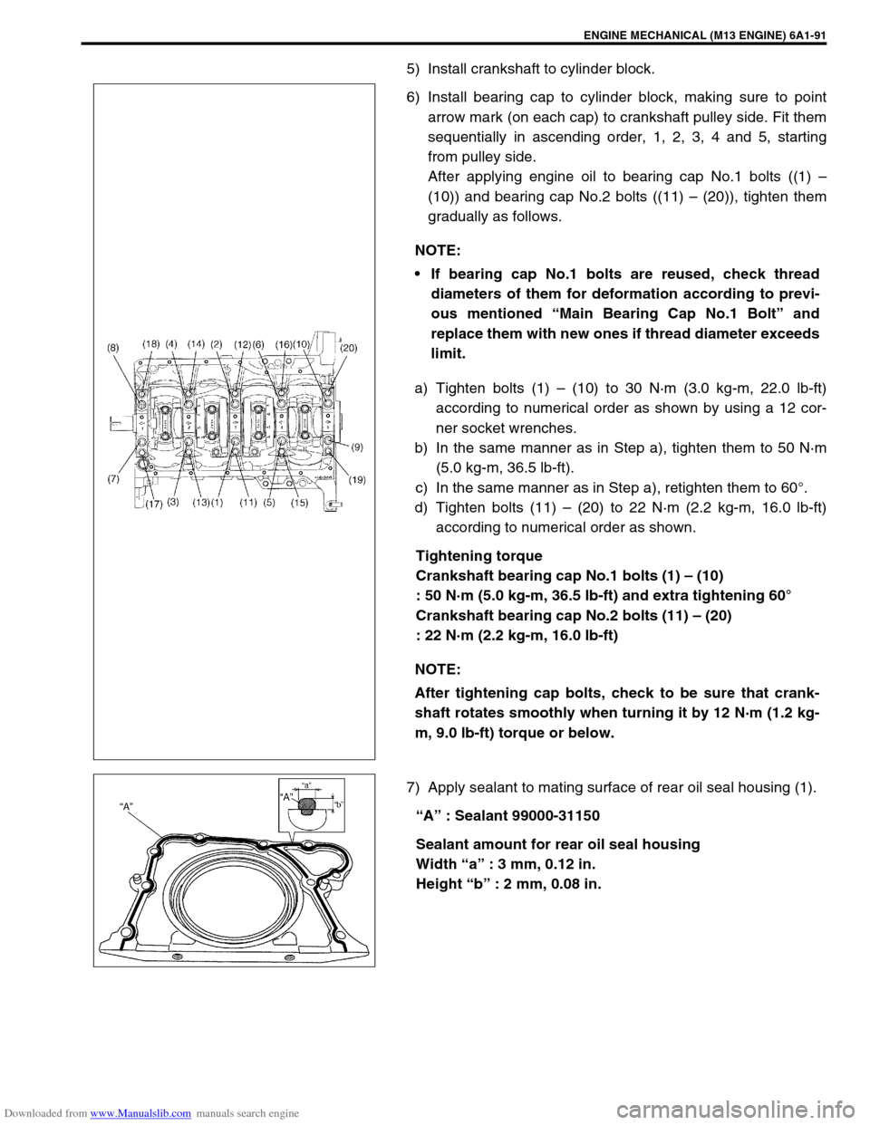
5) Install crankshaft to cylinder block.
6) Install bearing cap to cylinder block, making sure to point
arrow mark (on each cap) to crankshaft pulley side. Fit them
sequentially in ascending order, 1, 2, 3, 4 and 5, starting
from pulley side.
After applying engine oil to bearing cap No.1 bolts ((1) –
(10)) and bearing cap No.2 bolts ((11) – (20)), tighten them
gradually as follows.
a) Tighten bolts (1) – (10) to 30 N·m (3.0 kg-m, 22.0 lb-ft)
according to numerical order as shown by using a 12 cor-
ner socket wrenches.
b) In the same manner as in Step a), tighten them to 50 N·m
(5.0 kg-m, 36.5 lb-ft).
c) In the same manner as in Step a), retighten them to 60°.
d) Tighten bolts (11) – (20) to 22 N·m (2.2 kg-m, 16.0 lb-ft)
according to numerical order as shown.
Tightening torque
Crankshaft bearing cap No.1 bolts (1) – (10)
: 50 N·m (5.0 kg-m, 36.5 lb-ft) and extra tightening 60°
Crankshaft bearing cap No.2 bolts (11) – (20)
: 22 N·m (2.2 kg-m, 16.0 lb-ft)
7) Apply sealant to mating surface of rear oil seal housing (1).
“A” : Sealant 99000-31150
Sealant amount for rear oil seal housing
Width “a” : 3 mm, 0.12 in.
Height “b” : 2 mm, 0.08 in. NOTE:
If bearing cap No.1 bolts are reused, check thread
diameters of them for deformation according to previ-
ous mentioned “Main Bearing Cap No.1 Bolt” and
replace them with new ones if thread diameter exceeds
limit.
NOTE:
After tightening cap bolts, check to be sure that crank-
shaft rotates smoothly when turning it by 12 N·m (1.2 kg-
m, 9.0 lb-ft) torque or below.