Page 586 of 687

Downloaded from www.Manualslib.com manuals search engine ENGINE COOLING 6B-9
9) Run engine, with radiator cap removed, until radiator upper
hose is hot.
10) With engine idling, add coolant to radiator until level reaches
the bottom of filler neck. Install radiator cap, making sure
that the ear of cap lines up with reservoir hose.
Water Pump Belt Tension
1) Inspect belt for cracks, cuts, deformation, wear and cleanli-
ness. If it is necessary to replace belt, refer to “Water Pump
Belt and Cooling Fan” in this section.
2) Check belt for tension. Belt is in proper tension when it
deflects 4.5 to 5.5 mm (0.18 – 0.22 in.) under thumb pres-
sure (about 10 kg or 22 lb.).
Water pump belt tension
“a” : 4.5 – 5.5 mm (0.18 – 0.22 in.) as deflection / 10 kg (22
lbs)
3) If belt is too tight or too loose, adjust it to proper tension by
displacing generator position.
4) Tighten generator adjusting bolt and pivot bolts as specified
torque.
Tightening torque
Generator adjusting bolt (a) : 23 N·m (2.3 kg-m, 17.0 lb-ft)
Generator pivot bolts (b) : 50 N·m (5.0 kg-m, 36.0 lb-ft)
5) Connect negative cable at battery terminal.WARNING:
Disconnect negative cable at battery before checking and
adjusting belt tension.
NOTE:
When replacing belt with a new one, adjust belt tension
to 3 – 4 mm (0.12 – 0.16 in.).
Page 598 of 687

Downloaded from www.Manualslib.com manuals search engine ENGINE FUEL 6C-3
Fuel Pump Assembly
The fuel pump assembly (1) consists of fuel pump (6), fuel filter
(2), fuel level gauge (5) and fuel cut valve (4).
FUEL PUMP
For structure and operation of the fuel pump, refer to “Fuel Deliv-
ery System” in Section 6E.
FUEL CUT VALVE
The fuel cut valve consists of a float and a spring. It allows only
the fuel vapor to flow into the canister and prevents the fuel from
flowing into the canister.
Fuel Filler Cap
The fuel tank filler neck has a vacuum cap.
A ratchet tightening device on the threaded fuel filler cap reduces
the chances of incorrect installation, which would prevent sealing
fuel vapors.
After the gasket (2) on fuel filler cap and the filler neck flange con-
tact, the ratchet produces a loud clicking noise, indicating the seal
has been set.
This cap has a vacuum relief valve (1) inside.
The vacuum relief valve opens to relieve the vacuum created in
the fuel tank.
3. Suction filter
Page 620 of 687

Downloaded from www.Manualslib.com manuals search engine ENGINE AND EMISSION CONTROL SYSTEM 6E-15
On-Vehicle Service
Accelerator cable adjustment
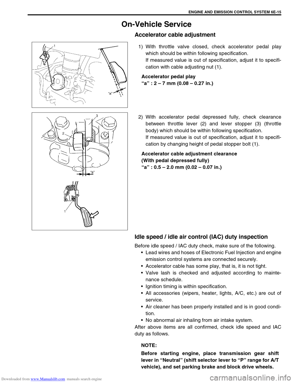
1) With throttle valve closed, check accelerator pedal play
which should be within following specification.
If measured value is out of specification, adjust it to specifi-
cation with cable adjusting nut (1).
Accelerator pedal play
“a” : 2 – 7 mm (0.08 – 0.27 in.)
2) With accelerator pedal depressed fully, check clearance
between throttle lever (2) and lever stopper (3) (throttle
body) which should be within following specification.
If measured value is out of specification, adjust it to specifi-
cation by changing height of pedal stopper bolt (1).
Accelerator cable adjustment clearance
(With pedal depressed fully)
“a” : 0.5 – 2.0 mm (0.02 – 0.07 in.)
Idle speed / idle air control (IAC) duty inspection
Before idle speed / IAC duty check, make sure of the following.
Lead wires and hoses of Electronic Fuel Injection and engine
emission control systems are connected securely.
Accelerator cable has some play, that is, it is not tight.
Valve lash is checked and adjusted according to mainte-
nance schedule.
Ignition timing is within specification.
All accessories (wipers, heater, lights, A/C, etc.) are out of
service.
Air cleaner has been properly installed and is in good condi-
tion.
No abnormal air inhaling from air intake system.
After above items are all confirmed, check idle speed and IAC
duty as follows.
NOTE:
Before starting engine, place transmission gear shift
lever in “Neutral” (shift selector lever to “P” range for A/T
vehicle), and set parking brake and block drive wheels.
Page 627 of 687

Downloaded from www.Manualslib.com manuals search engine 6E-22 ENGINE AND EMISSION CONTROL SYSTEM
Fuel Delivery System
Fuel pressure inspection
1) Relieve fuel pressure in fuel feed line referring to “Fuel Pres-
sure Relief Procedure” in Section 6.
2) Disconnect fuel feed hose from fuel delivery pipe.
3) Connect special tools and hose between fuel delivery pipe
(1) and fuel feed hose (2) as shown in figure, and clamp
hoses securely to ensure no leaks occur during checking.
Special tool
(A) : 09912-58442
(B) : 09912-58432
(C) : 09912-58490
4) Check that battery voltage is above 11 V.
5) Turn ignition switch ON to operate fuel pump and after 2 sec-
onds turn it OFF. Repeat this 3 or 4 times and then check
fuel pressure.
Fuel pressure specification WARNING:
Be sure to perform work in a well-ventilated area and
away from any open flames, or there is a risk of a fire
breaking out.
CAUTION:
A small amount of fuel may be released when fuel hose is
disconnected. Place container under the joint with a
shop cloth so that released fuel is caught in container or
absorbed in cloth. Place that cloth in an approved con-
tainer.
3. Fuel return pipe
CONDITION FUEL PRESSURE
With fuel pump operating and
engine stopped270 – 310 kPa
2.7 – 3.1 kg/cm
2,
38.4 – 44.0 psi
At specified idle speed 210 – 260 kPa
2.1 – 2.6 kg/cm
2,
29.8 – 37.0 psi
With 1 min. after engine (fuel
pump) stop (Pressure
reduces as time passes)over 200 kPa
2.0 kg/cm
2, 28.4 psi
Page 628 of 687

Downloaded from www.Manualslib.com manuals search engine ENGINE AND EMISSION CONTROL SYSTEM 6E-23
6) Start engine and warm it up to normal operating tempera-
ture.
7) Measure fuel pressure at idling.
If measured pressure doesn’t satisfy specification, refer to
“Diagnostic Flow Table B-3” in Section 6 and check each
possibly defective part. Replace if found defective.
8) After checking fuel pressure, remove fuel pressure gauge.
9) Remove special tools from fuel delivery pipe.
10) Connect fuel feed hose to fuel delivery pipe and clamp it
securely.
11) With engine “OFF” and ignition switch “ON”, check for fuel
leaks.
Fuel pump
ON-VEHICLE INSPECTION
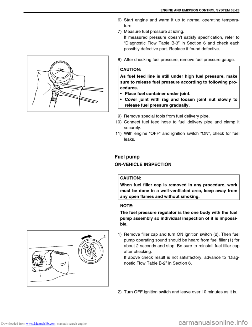
1) Remove filler cap and turn ON ignition switch (2). Then fuel
pump operating sound should be heard from fuel filler (1) for
about 2 seconds and stop. Be sure to reinstall fuel filler cap
after checking.
If above check result is not satisfactory, advance to “Diag-
nostic Flow Table B-2” in Section 6.
2) Turn OFF ignition switch and leave over 10 minutes as it is.CAUTION:
As fuel feed line is still under high fuel pressure, make
sure to release fuel pressure according to following pro-
cedures.
Place fuel container under joint.
Cover joint with rag and loosen joint nut slowly to
release fuel pressure gradually.
CAUTION:
When fuel filler cap is removed in any procedure, work
must be done in a well-ventilated area, keep away from
any open flames and without smoking.
NOTE:
The fuel pressure regulator is the one body with the fuel
pump assembly so individual inspection of it is impossi-
ble.
Page 630 of 687

Downloaded from www.Manualslib.com manuals search engine ENGINE AND EMISSION CONTROL SYSTEM 6E-25
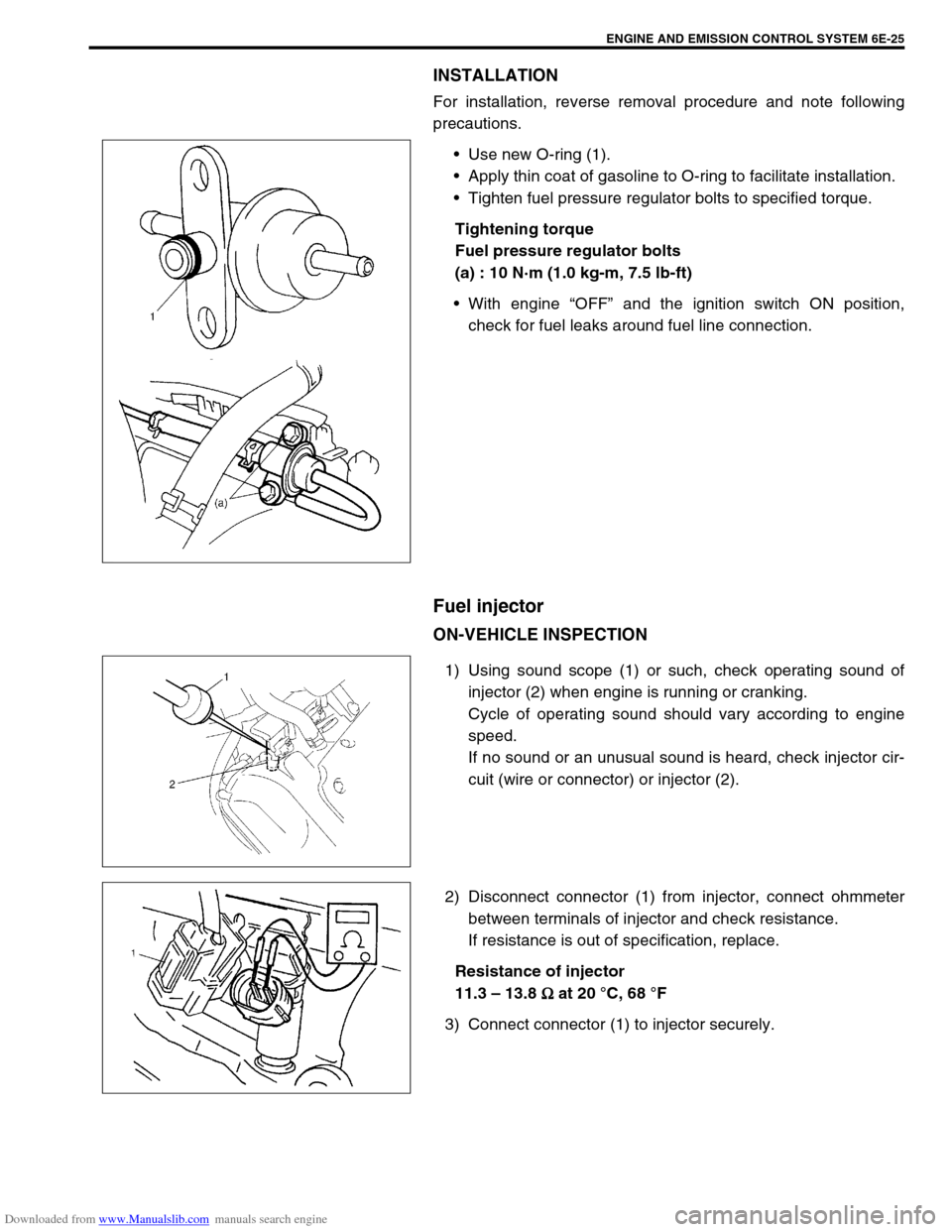
INSTALLATION
For installation, reverse removal procedure and note following
precautions.
Use new O-ring (1).
Apply thin coat of gasoline to O-ring to facilitate installation.
Tighten fuel pressure regulator bolts to specified torque.
Tightening torque
Fuel pressure regulator bolts
(a) : 10 N·m (1.0 kg-m, 7.5 lb-ft)
With engine “OFF” and the ignition switch ON position,
check for fuel leaks around fuel line connection.
Fuel injector
ON-VEHICLE INSPECTION
1) Using sound scope (1) or such, check operating sound of
injector (2) when engine is running or cranking.
Cycle of operating sound should vary according to engine
speed.
If no sound or an unusual sound is heard, check injector cir-
cuit (wire or connector) or injector (2).
2) Disconnect connector (1) from injector, connect ohmmeter
between terminals of injector and check resistance.
If resistance is out of specification, replace.
Resistance of injector
11.3 – 13.8
Ω
ΩΩ Ω at 20 °C, 68 °F
3) Connect connector (1) to injector securely.
Page 631 of 687

Downloaded from www.Manualslib.com manuals search engine 6E-26 ENGINE AND EMISSION CONTROL SYSTEM
REMOVAL
1) Relieve fuel pressure according to procedure described in
“Fuel Pressure Relief Procedure” in Section 6.
2) Disconnect battery negative cable at battery.
3) Disconnect fuel injector couplers and release wire harness
from clamps.
4) Remove clamp bolt for fuel feed pipe and return pipe.
5) Remove fuel delivery pipe bolts (2).
6) Remove fuel injector(s) (3).
INSPECTION
1) Install injector (3) and fuel pressure regulator (4) to special
tool (injector checking tool).
Special tool
(A) : 09912-58421
2) Connect special tools (hose and attachment) to fuel feed
hose (1) of vehicle.
Special tool
(B) : 09912-58432
3) Connect special tool (test lead) to injector.
Special tool
(C) : 09930-88530
4) Install suitable vinyl tube onto injector nozzle to prevent fuel
from splashing out when injecting. CAUTION:
A small amount of fuel may come out after removal of
fuel injectors, cover them with shop cloth.
WARNING:
As fuel is injected in this inspection, perform in a well
ventilated area and away from open flames.
Use special care to prevent sparking when connecting
and disconnecting test lead to and from battery.
2. Fuel return line
Page 642 of 687

Downloaded from www.Manualslib.com manuals search engine ENGINE AND EMISSION CONTROL SYSTEM 6E-37
Fuel cut operation
INSPECTION
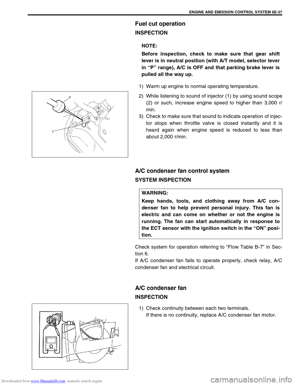
1) Warm up engine to normal operating temperature.
2) While listening to sound of injector (1) by using sound scope
(2) or such, increase engine speed to higher than 3,000 r/
min.
3) Check to make sure that sound to indicate operation of injec-
tor stops when throttle valve is closed instantly and it is
heard again when engine speed is reduced to less than
about 2,000 r/min.
A/C condenser fan control system
SYSTEM INSPECTION
Check system for operation referring to “Flow Table B-7” in Sec-
tion 6.
If A/C condenser fan fails to operate properly, check relay, A/C
condenser fan and electrical circuit.
A/C condenser fan
INSPECTION
1) Check continuity between each two terminals.
If there is no continuity, replace A/C condenser fan motor. NOTE:
Before inspection, check to make sure that gear shift
lever is in neutral position (with A/T model, selector lever
in “P” range), A/C is OFF and that parking brake lever is
pulled all the way up.
WARNING:
Keep hands, tools, and clothing away from A/C con-
denser fan to help prevent personal injury. This fan is
electric and can come on whether or not the engine is
running. The fan can start automatically in response to
the ECT sensor with the ignition switch in the “ON” posi-
tion.