Page 661 of 687

Downloaded from www.Manualslib.com manuals search engine 6G-2 CRANKING SYSTEM
General Description
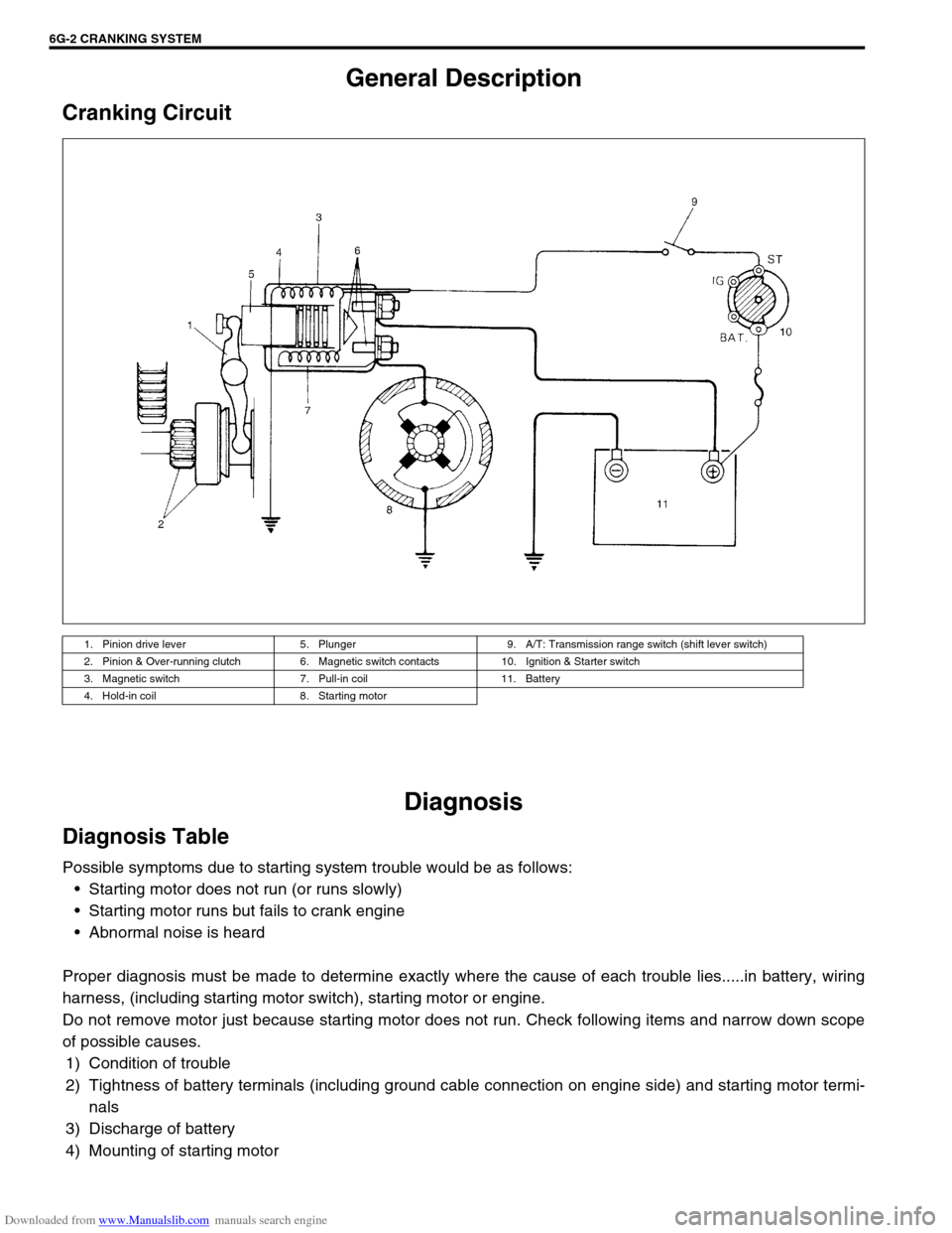
Cranking Circuit
Diagnosis
Diagnosis Table
Possible symptoms due to starting system trouble would be as follows:
Starting motor does not run (or runs slowly)
Starting motor runs but fails to crank engine
Abnormal noise is heard
Proper diagnosis must be made to determine exactly where the cause of each trouble lies.....in battery, wiring
harness, (including starting motor switch), starting motor or engine.
Do not remove motor just because starting motor does not run. Check following items and narrow down scope
of possible causes.
1) Condition of trouble
2) Tightness of battery terminals (including ground cable connection on engine side) and starting motor termi-
nals
3) Discharge of battery
4) Mounting of starting motor
1. Pinion drive lever 5. Plunger 9. A/T: Transmission range switch (shift lever switch)
2. Pinion & Over-running clutch 6. Magnetic switch contacts 10. Ignition & Starter switch
3. Magnetic switch 7. Pull-in coil 11. Battery
4. Hold-in coil 8. Starting motor
Page 668 of 687

Downloaded from www.Manualslib.com manuals search engine CHARGING SYSTEM 6H-1
6F1
6F2
6G
6K
7D
7E
7F
7C1
7D
7E
7F
8A
8B
8C
8D
8E
9
7A
6H
7B1
10B
SECTION 6H
CHARGING SYSTEM
CONTENTS
General Description ....................................... 6H-2
Battery .......................................................... 6H-2
Generator ..................................................... 6H-4
Diagnosis ........................................................ 6H-6
Battery .......................................................... 6H-6
Generator ..................................................... 6H-7
On-Vehicle Service......................................... 6H-9
Battery .......................................................... 6H-9
Jump starting in case of emergency......... 6H-9
Dismounting ........................................... 6H-11
Handling ................................................. 6H-11
Remounting ............................................ 6H-11Generator ................................................... 6H-11
Generator belt ........................................ 6H-11
Unit Repair Overhaul ................................... 6H-12
Generator ................................................... 6H-12
Dismounting ........................................... 6H-12
Remounting ............................................ 6H-13
Disassembly and reassembly ................ 6H-13
Inspection ............................................... 6H-14
Specifications............................................... 6H-17
Battery........................................................ 6H-17
Generator ................................................... 6H-17
Tightening Torque Specification ................ 6H-17
WARNING:
For vehicles equipped with Supplemental Restraint (Air Bag) System
Service on and around the air bag system components or wiring must be performed only by an
authorized SUZUKI dealer. Refer to “Air Bag System Components and Wiring Location View” under
“General Description” in air bag system section in order to confirm whether you are performing ser-
vice on or near the air bag system components or wiring. Please observe all WARNINGS and “Ser-
vice Precautions” under “On-Vehicle Service” in air bag system section before performing service
on or around the air bag system components or wiring. Failure to follow WARNINGS could result in
unintentional activation of the system or could render the system inoperative. Either of these two
conditions may result in severe injury.
Technical service work must be started at least 90 seconds after the ignition switch is turned to the
“LOCK” position and the negative cable is disconnected from the battery. Otherwise, the system
may be activated by reserve energy in the Sensing and Diagnostic Module (SDM).
Page 669 of 687

Downloaded from www.Manualslib.com manuals search engine 6H-2 CHARGING SYSTEM
General Description
Battery
The battery has three major functions in the electrical system.
It is a source of electrical energy for cranking the engine.
It acts as a voltage stabilizer for the electrical system.
It can, for a limited time, provide energy when the electrical
load exceeds the output of the generator.
CARRIER AND HOLD-DOWN
The battery carrier should be in good condition so that it will sup-
port the battery securely and keep it level.
Before installing the battery, the battery carrier and hold-down
clamp should be clean and free from corrosion and make certain
there are no parts in carrier.
To prevent the battery from shaking in its carrier, the hold-down
bolts should be tight enough but not over-tightened.
ELECTROLYTE FREEZING
The freezing point of electrolyte depends on its specific gravity.
Since freezing may ruin a battery, it should be protected against
freezing by keeping it in a fully charged condition. If a battery is
frozen accidentally, it should not be charged until it is warmed.
SULFATION
If the battery is allowed to stand for a long period in discharged
condition, the lead sulfate becomes converted into a hard, crystal-
line substance, which will not easily turn back to the active mate-
rial again during the subsequent recharging. “Sulfation” means
the result as well as the process of that reaction.
Such a battery can be revived by very slow charging and may be
restored to usable condition but its capacity is lower than before.
Page 686 of 687

Downloaded from www.Manualslib.com manuals search engine EXHAUST SYSTEM 6K-1
6F1
6F2
6G
6H
7D
7E
7F
7D
7E
7F
8A
8B
8C
8D
8E
9
7A1
6K
7C1
SECTION 6K
EXHAUST SYSTEM
CONTENTS
General Description ........................................6K-1
Maintenance ....................................................6K-1On-Vehicle Service ......................................... 6K-2
Exhaust Manifold .......................................... 6K-2
Exhaust Pipe ................................................. 6K-2
General Description
The exhaust system of this vehicle consists of the exhaust manifold, exhaust center pipe, muffler, seals, etc.
The catalytic converter is an emission control device added to the exhaust system to lower the level of Hydro-
carbon (HC), Carbon Monoxide (CO) and Oxides of Nitrogen (NOx) pollutants in the exhaust gas. The catalyst
in the catalytic converter is of “Three way” type.
Maintenance
At every interval of periodic maintenance service, and when vehicle is raised for other service, check exhaust
system as follows:
Check rubber mountings for damage, deterioration and out of position.
Check exhaust system for leakage, loose connection, dent and damage.
If bolts or nuts are loosened, tighten them to specified torque. Refer to “Components” in this section.
Check nearby body areas for damaged, missing, or mispositioned part, open seam, hole, loose connection
or any other defect which could permit exhaust fumes to seep into vehicle.
Make sure that exhaust system components have enough clearance from underbody to avoid overheating
and possible damage to passenger compartment carpet.
Any defect should be fixed at once. NOTE:
Whether following parts are used in the particular vehicle or not depends on specification. Be sure to
bear this in mind when performing service work.
Three-Way Catalytic Converter (TWC)
CAUTION:
Be sure to use UNLEADED FUEL for the catalytic converter equipped vehicle. Use of LEADED FUEL
will affect performance of the catalytic converter adversely to a great extent.
WARNING:
To avoid danger of being burned, do not touch exhaust system when system is hot.
Any service on exhaust system should be performed when system is cool.