Page 2182 of 4555
MT-26
TRANSAXLE ASSEMBLY
Final Drive Components
DISASSEMBLY
1. Remove plug (for 2WD models) or filler plug (for 4WD models) from clutch housing.
2. Remove drain plug and plug from transaxle case.
3. Remove park/neutral position switch and back-up lamp switch
from transaxle case.
4. Remove shift check and stopper bolt from transaxle case, and
then remove control assembly from transaxle case.
1. Differential side bearing outer race
(clutch housing side)2. Differential side bearing (clutch
housing side)3. Speedometer drive gear (for 2WD
models)
4. Differential case 5. Final gear 6. Differential side bearing (transaxle
case side)
7. Differential side bearing outer race
(transaxle case side)8. Differential side bearing adjusting
shim9. Pinion mate shaft
10. Side gear 11. Side gear thrust washer 12. Pinion mate gear
13. Pinion mate thrust washer 14. Retaining pin
PCIB0869E
SCIA0389E
Page 2186 of 4555
MT-30
TRANSAXLE ASSEMBLY
35. Remove input shaft oil seal from clutch housing.
CAUTION:
Be careful not to damage clutch housing.
ASSEMBLY
1. Install input shaft oil seal to clutch housing using the drift.
CAUTION:
Do not reuse input shaft oil seal.
2. Install differential side oil seal until it become flush with end face
of clutch housing using the drift.
CAUTION:
�Do not reuse differential side oil seal.
�Apply multi-purpose grease onto oil seal lip. (For 4WD
models)
3. Install oil channel on mainshaft side.
CAUTION:
Be careful with the orientation of installation.
SCIA0398E
Dimension A: 1.8 - 2.8 mm (0.071 - 0.110 in)
PCIB0873E
SCIA1070J
SCIA0986E
Page 2191 of 4555

TRANSAXLE ASSEMBLY
MT-35
D
E
F
G
H
I
J
K
L
MA
B
MT
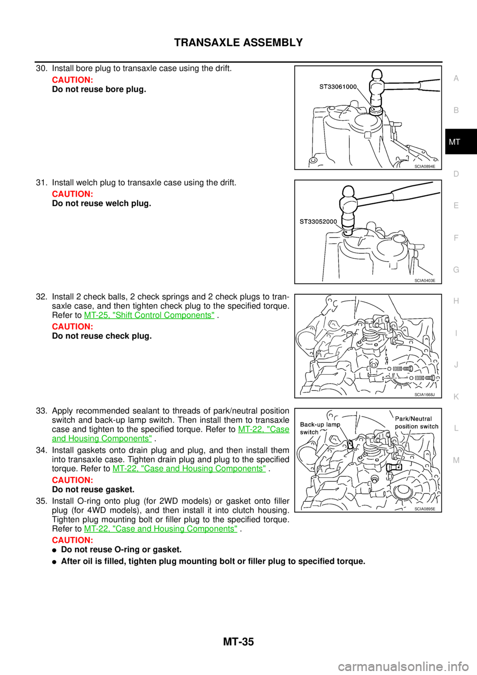
30. Install bore plug to transaxle case using the drift.
CAUTION:
Do not reuse bore plug.
31. Install welch plug to transaxle case using the drift.
CAUTION:
Do not reuse welch plug.
32. Install 2 check balls, 2 check springs and 2 check plugs to tran-
saxle case, and then tighten check plug to the specified torque.
Refer to MT-25, "
Shift Control Components" .
CAUTION:
Do not reuse check plug.
33. Apply recommended sealant to threads of park/neutral position
switch and back-up lamp switch. Then install them to transaxle
case and tighten to the specified torque. Refer to MT-22, "
Case
and Housing Components" .
34. Install gaskets onto drain plug and plug, and then install them
into transaxle case. Tighten drain plug and plug to the specified
torque. Refer to MT-22, "
Case and Housing Components" .
CAUTION:
Do not reuse gasket.
35. Install O-ring onto plug (for 2WD models) or gasket onto filler
plug (for 4WD models), and then install it into clutch housing.
Tighten plug mounting bolt or filler plug to the specified torque.
Refer to MT-22, "
Case and Housing Components" .
CAUTION:
�Do not reuse O-ring or gasket.
�After oil is filled, tighten plug mounting bolt or filler plug to specified torque.
SCIA0894E
SCIA0403E
SCIA1668J
SCIA0895E
Page 2200 of 4555
MT-44
TRANSAXLE ASSEMBLY
Final Drive Components
DISASSEMBLY
1. Remove plug (for 2WD models) or filler plug (for 4WD models) from clutch housing.
2. Remove drain plug and plug from transaxle case.
3. Remove park/neutral position switch and back-up lamp switch
from transaxle case.
4. Remove shift check and stopper bolt from transaxle case, and
then remove control assembly from transaxle case.
1. Differential side bearing outer race
(clutch housing side)2. Differential side bearing (clutch
housing side)3. Speedometer drive gear (for 2WD
models)
4. Differential case 5. Final gear 6. Differential side bearing (transaxle
case side)
7. Differential side bearing outer race
(transaxle case side)8. Differential side bearing adjusting
shim9. Pinion mate shaft
10. Side gear 11. Side gear thrust washer 12. Pinion mate gear
13. Pinion mate thrust washer 14. Retaining pin
PCIB0869E
SCIA0389E
Page 2204 of 4555
MT-48
TRANSAXLE ASSEMBLY
37. Remove differential side bearing outer race from clutch housing
using the puller.
38. Remove input shaft oil seal from clutch housing.
CAUTION:
Be careful not to damage clutch housing.
ASSEMBLY
1. Install input shaft oil seal to clutch housing using the drift.
CAUTION:
Do not reuse input shaft oil seal.
2. Install differential side oil seal until it become flush with end face
of clutch housing using the drift.
CAUTION:
�Do not reuse differential side oil seal.
�Apply multi-purpose grease onto oil seal lip. (For 4WD
models)
SCIA1069J
SCIA0398E
Dimension A: 1.8 - 2.8 mm (0.071 - 0.110 in)
PCIB0873E
SCIA1070J
Page 2210 of 4555

MT-54
TRANSAXLE ASSEMBLY
37. Apply recommended sealant to threads of park/neutral position
switch and back-up lamp switch. Then install them to transaxle
case and tighten to the specified torque. Refer to MT-40, "
Case
and Housing Components" .
38. Install gaskets onto drain plug and plug, and then install them
into transaxle case. Tighten drain plug and plug to the specified
torque. Refer to MT-40, "
Case and Housing Components" .
CAUTION:
Do not reuse gasket.
39. Install O-ring onto plug (for 2WD models) or gasket onto filler
plug (for 4WD models), and then install it into clutch housing.
Tighten plug mounting bolt or filler plug to the specified torque.
Refer to MT-40, "
Case and Housing Components" .
CAUTION:
�Do not reuse O-ring or gasket.
�After oil is filled, tighten plug mounting bolt or filler plug to specified torque.
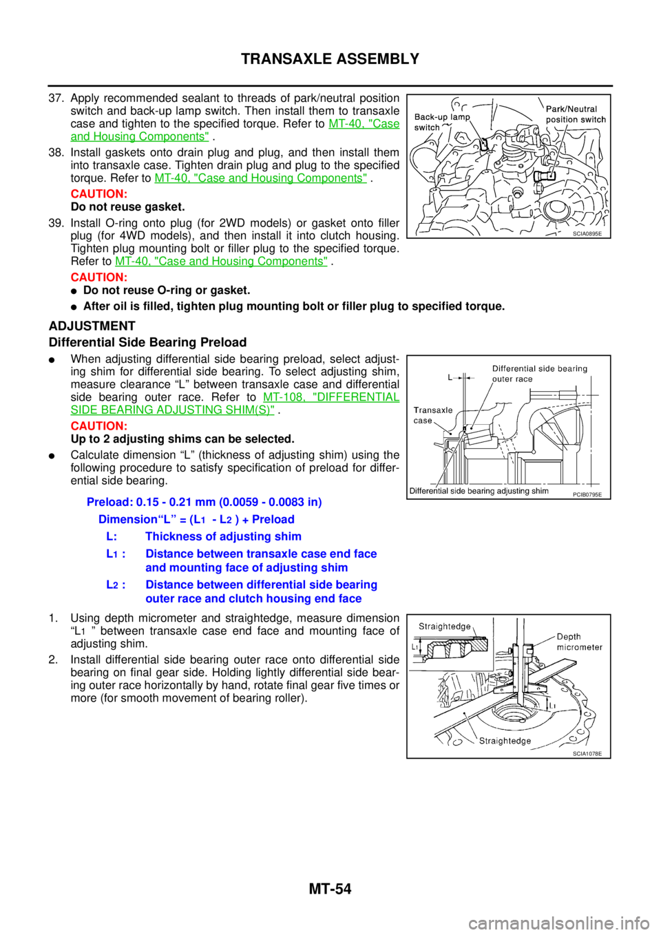
ADJUSTMENT
Differential Side Bearing Preload
�When adjusting differential side bearing preload, select adjust-
ing shim for differential side bearing. To select adjusting shim,
measure clearance “L” between transaxle case and differential
side bearing outer race. Refer to MT-108, "
DIFFERENTIAL
SIDE BEARING ADJUSTING SHIM(S)" .
CAUTION:
Up to 2 adjusting shims can be selected.
�Calculate dimension “L” (thickness of adjusting shim) using the
following procedure to satisfy specification of preload for differ-
ential side bearing.
1. Using depth micrometer and straightedge, measure dimension
“L
1 ” between transaxle case end face and mounting face of
adjusting shim.
2. Install differential side bearing outer race onto differential side
bearing on final gear side. Holding lightly differential side bear-
ing outer race horizontally by hand, rotate final gear five times or
more (for smooth movement of bearing roller).
SCIA0895E
Preload: 0.15 - 0.21 mm (0.0059 - 0.0083 in)
Dimension“L” = (L
1 - L2 ) + Preload
L: Thickness of adjusting shim
L
1 : Distance between transaxle case end face
and mounting face of adjusting shim
L
2 : Distance between differential side bearing
outer race and clutch housing end face
PCIB0795E
SCIA1078E
Page 2259 of 4555
SERVICE DATA AND SPECIFICATIONS (SDS)
MT-103
D
E
F
G
H
I
J
K
L
MA
B
MT
SERVICE DATA AND SPECIFICATIONS (SDS)PFP:00030
General SpecificationsECS008CE
TRANSAXLE
Engine type QR20DE QR25DE YD22DDTi
Transaxle model RS5F51A RS6F51A
Axle type 2WD 4WD 2WD 4WD
Model code number EQ500 EQ000 EQ008 EQ078 EQ068
Number of speed 5 6
Synchromesh type Warner
Shift pattern
5 speed
6 speed
Gear ratio 1st 3.500 3.416 3.500
2nd 1.944
3rd 1.258
4th 0.947
5th 0.772 0.733 0.772
6th — 0.630
Reverse 3.374 3.252 3.374
Final gear 4.750 4.428
Number of
teethInput gear 1st 14 12 14
2nd 18
3rd 31
4th 38
5th 44 45 44
6th — 46
Reverse 14 12 14
Main gear 1st 49 41 49
2nd 35
3rd 39
4th 36
5th 34 33 34
6th — 29
Reverse 38
SCIA0821E
SCIA0955E
Page 2260 of 4555

MT-104
SERVICE DATA AND SPECIFICATIONS (SDS)
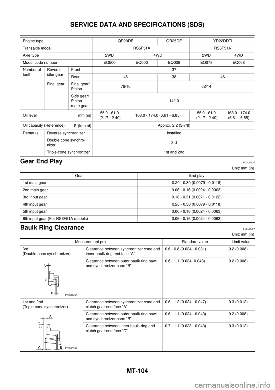
Gear End PlayECS008CF
Unit: mm (in)
Baulk Ring ClearanceECS00CV4
Unit: mm (in) Number of
teethReverse
idler gearFront 37
Rear 46 38 46
Final gear Final gear/
Pinion76/16 62/14
Side gear/
Pinion
mate gear14/10
Oil level mm (in)55.0 - 61.0
(2.17 - 2.40)168.0 - 174.0 (6.61 - 6.85)55.0 - 61.0
(2.17 - 2.40)168.0 - 174.0
(6.61 - 6.85)
Oil capacity (Reference)
(Imp pt)Approx. 2.2 (3-7/8)
Remarks Reverse synchronizer Installed
Double-cone synchro-
nizer3rd
Triple-cone synchronizer 1st and 2nd Engine type QR20DE QR25DE YD22DDTi
Transaxle model RS5F51A RS6F51A
Axle type 2WD 4WD 2WD 4WD
Model code number EQ500 EQ000 EQ008 EQ078 EQ068
Gear End play
1st main gear0.20 - 0.30 (0.0079 - 0.0118)
2nd main gear 0.06 - 0.16 (0.0024 - 0.0063)
3rd input gear0.18 - 0.31 (0.0071 - 0.0122)
4th input gear0.20 - 0.30 (0.0079 - 0.0118)
5th input gear0.06 - 0.16 (0.0024 - 0.0063)
6th input gear (For RS6F51A models) 0.06 - 0.16 (0.0024 - 0.0063)
Measurement point Standard value Limit value
3rd
(Double-cone synchronizer)Clearance between synchronizer cone and
inner baulk ring end face “A” 0.6 - 0.8 (0.024 - 0.031) 0.2 (0.008)
Clearance between outer baulk ring pawl
and synchronizer cone “B”0.6 - 1.1 (0.024 -0.043) 0.2 (0.008)
1st and 2nd
(Triple-cone synchronizer)Clearance between synchronizer cone and
clutch gear end face “A”0.6 - 1.2 (0.024 - 0.047) 0.3 (0.012)
Clearance between outer baulk ring pawl
and synchronizer cone “B”0.6 - 1.1 (0.024 - 0.043) 0.2 (0.008)
Clearance between inner baulk ring and
clutch gear end face “C”0.7 - 1.1 (0.028 - 0.043) 0.3 (0.012)
PCIB0249E
PCIB0835J