Page 2160 of 4555

MT-4
PREPARATION
PREPARATIONPFP:00002
Special Service ToolsECS008BN
Tool number
Tool nameDescription
KV381054S0
Puller
�Removing differential side bearing outer
race
�Removing mainshaft front bearing
ST35321000
Drift
a: 49 mm (1.93 in) dia.
b: 41 mm (1.61 in) dia.
�Installing input shaft oil seal
�Installing reverse main gear
�Installing 1st main gear bushing
�Installing 1st-2nd synchronizer hub
assembly
�Installing 2nd main gear bushing
�Installing 3rd main gear
�Removing differential side bearing (clutch
housing side for 4WD models)
ST30720000
Drift
a: 77 mm (3.03 in) dia.
b: 55.5 mm (2.185 in) dia.
�Installing differential side oil seal
�Installing differential side bearing outer race
�Installing mainshaft rear bearing
�Installing differential side bearing
ST33200000
Drift
a: 60 mm (2.36 in) dia.
b: 44.5 mm (1.752 in) dia.
�Installing mainshaft front bearing
�Installing 6th input gear bushing
(RS6F51A)
�Installing 4th main gear
�Installing 5th main gear
�Installing 6th main gear (RS6F51A)
KV40105320
Drift
a: 88 mm (3.46 in) dia.Installing differential side bearing outer race
ST33061000
Drift
a: 38 mm (1.50 in) dia.
b: 28.5 mm (1.122 in) dia.
�Installing bore plug
�Removing differential side bearing (clutch
housing side for 2WD models)
�Removing differential side bearing
(transaxle case side for 4WD models)
ZZA0601D
ZZA1000D
ZZA0811D
ZZA1002D
ZZA0898D
ZZA1000D
Page 2162 of 4555
MT-6
PREPARATION
Commercial Service ToolsECS008BO
ST30031000
PullerMeasuring wear of inner baulk ring
KV40101630
Drift
a: 68 mm (2.68 in) dia.
b: 60 mm (2.36 in) dia.Installing reverse main gear
KV38102510
Drift
a: 71 mm (2.80 in) dia.
b: 65 mm (2.56 in) dia.
�Installing 1st main gear bushing
�Installing 1st-2nd synchronizer hub
assembly
�Installing differential side bearing (clutch
housing side for 2WD models)
�Installing differential side bearing (transaxle
case side for 4WD models)
KV40104830
Drift
a: 70 mm (2.76 in) dia.
b: 63.5 mm (2.500 in) dia.Installing differential side bearing (clutch
housing side for 4WD models)
ST15243000
Drift
a: 30 mm (1.18 in) dia.Measuring end play of side gear Tool number
Tool nameDescription
ZZA0537D
ZZA1003D
ZZA0838D
ZZA0936D
SCIA1088J
Tool nameDescription
PullerRemoving each bearing, gear and bushing
ZZA0537D
Page 2166 of 4555
MT-10
DESCRIPTION
4WD models
PCIB0773E
1. 3rd input gear 2. 3rd-4th synchronizer hub 3. 3rd-4th coupling sleeve
4. 4th input gear 5. 5th input gear 6. 5th synchronizer hub
7. 5th coupling sleeve 8. Input shaft rear bearing 9. Mainshaft rear bearing
10. 5th main gear 11. 4th main gear 12. 3rd main gear
13. 2nd main gear 14. 1st-2nd coupling sleeve 15. 1st-2nd synchronizer hub
16. 1st main gear 17. Reverse main gear 18. Differential side bearing
19. Differential case 20. Final gear 21. Differential side bearing
22. Mainshaft front bearing 23. Mainshaft 24. Input shaft
25. Input shaft front bearing 26. Clutch housing 27. Reverse idler shaft
28. Reverse idler gear (Front) 29. Reverse coupling sleeve 30. Reverse synchronizer hub
31. Reverse idler gear (Rear) 32. 5th input gear 33. 5th-6th synchronizer hub
34. 5th-6th coupling sleeve 35. 6th input gear 36. Input shaft rear bearing
37. Mainshaft rear bearing 38. 5th main gear 39. 6th main gear
Page 2168 of 4555

MT-12
M/T OIL
M/T OILPFP:KLD20
Changing M/T OilECS008BR
DRAINING
1. Start engine and let it run to warm up transaxle.
2. Stop engine. Remove drain plug and then drain oil.
3. Set a gasket on drain plug and install it to transaxle case. Tighten drain plug to the specified torque. Refer
to MT-22, "
Case and Housing Components" (RS5F51A) or MT-40, "Case and Housing Components"
(RS6F51A).
CAUTION:
Do not reuse gasket.
FILLING
1. Remove plug (for 2WD models) or filler plug (for 4WD models).
Fill with new oil to transaxle.
2. After refilling oil, check oil level.
3. Set a O-ring on plug (for 2WD models) or gasket on filler plug
(for 4WD models) and then install it to clutch housing.
CAUTION:
Do not reuse O-ring or gasket.
4. Tighten plug mounting bolt (for 2WD models) or filler plug (for 4WD models) to the specified torque. Refer
to MT-22, "
Case and Housing Components" (RS5F51A) or MT-40, "Case and Housing Components"
(RS6F51A).
Checking M/T OilECS008BS
OIL LEAKAGE AND OIL LEVEL
�Make sure that oil is not leaking from transaxle or around it.
�Remove plug (for 2WD models) or filler plug (for 4WD models).
�Measure oil level using a suitable gauge as shown in the figure, and then check if it is within the specifica-
tions.
CAUTION:
Do not start engine while checking oil level.
–For 2WD modelsOil grade and viscosity: Refer to MA-17, "
Fluids and
Lubricants" .
Oil capacity (reference):
Approx. 2.2 (3-7/8 lmp pt)
PCIB1572E
Oil level “L” : 55.0 - 61.0 mm (2.17 - 2.40 in)
PCIB1477E
Page 2169 of 4555
M/T OIL
MT-13
D
E
F
G
H
I
J
K
L
MA
B
MT
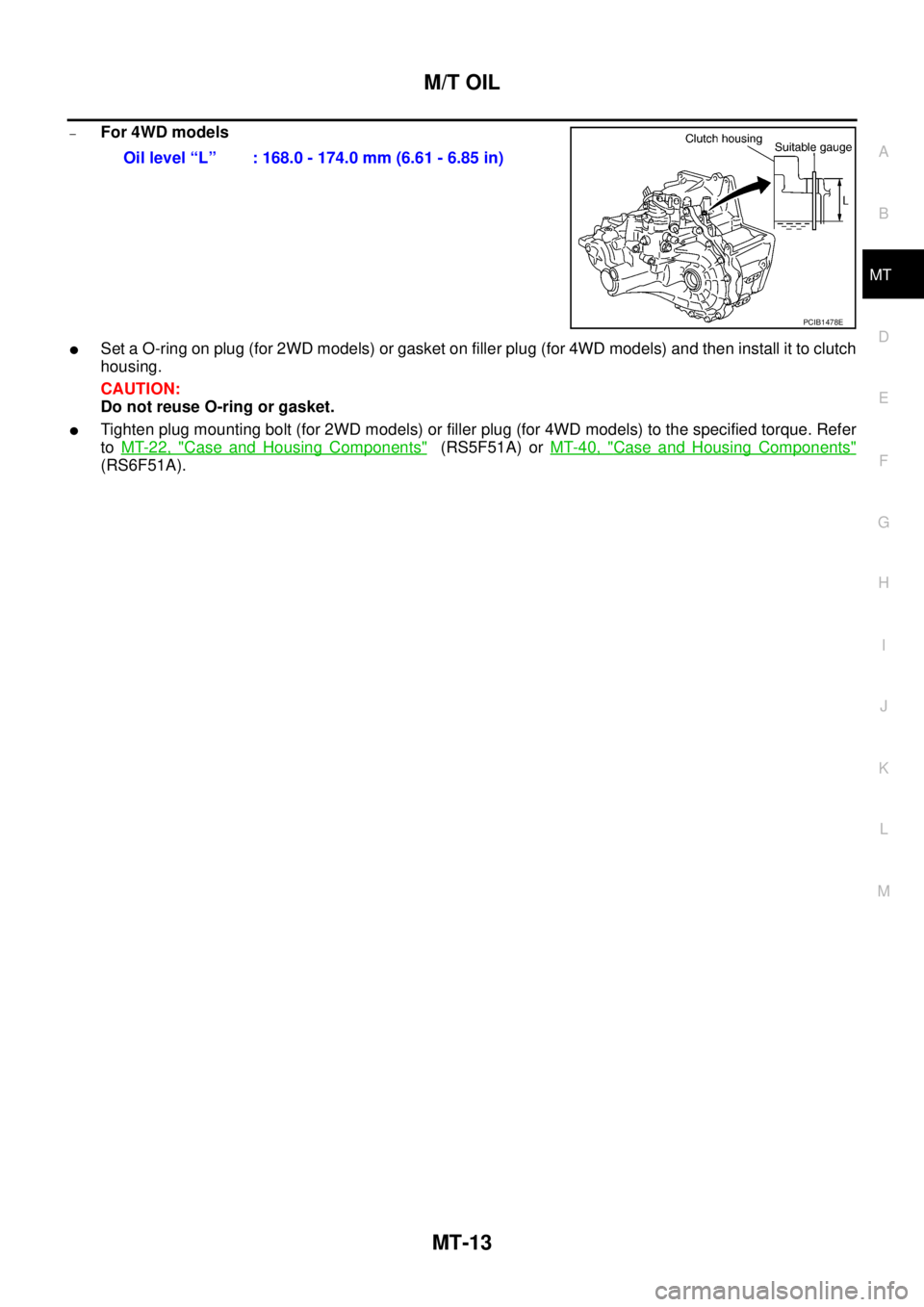
–For 4WD models
�Set a O-ring on plug (for 2WD models) or gasket on filler plug (for 4WD models) and then install it to clutch
housing.
CAUTION:
Do not reuse O-ring or gasket.
�Tighten plug mounting bolt (for 2WD models) or filler plug (for 4WD models) to the specified torque. Refer
to MT-22, "
Case and Housing Components" (RS5F51A) or MT-40, "Case and Housing Components"
(RS6F51A).Oil level “L” : 168.0 - 174.0 mm (6.61 - 6.85 in)
PCIB1478E
Page 2170 of 4555
MT-14
SIDE OIL SEAL
SIDE OIL SEALPFP:32113
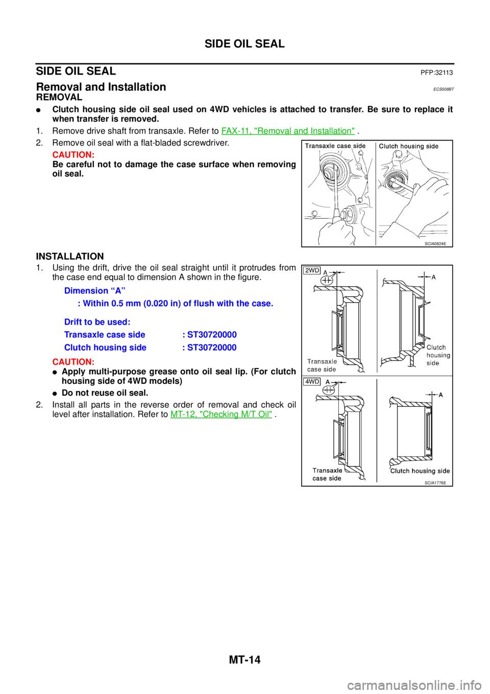
Removal and InstallationECS008BT
REMOVAL
�Clutch housing side oil seal used on 4WD vehicles is attached to transfer. Be sure to replace it
when transfer is removed.
1. Remove drive shaft from transaxle. Refer to FAX-11, "
Removal and Installation" .
2. Remove oil seal with a flat-bladed screwdriver.
CAUTION:
Be careful not to damage the case surface when removing
oil seal.
INSTALLATION
1. Using the drift, drive the oil seal straight until it protrudes from
the case end equal to dimension A shown in the figure.
CAUTION:
�Apply multi-purpose grease onto oil seal lip. (For clutch
housing side of 4WD models)
�Do not reuse oil seal.
2. Install all parts in the reverse order of removal and check oil
level after installation. Refer to MT-12, "
Checking M/T Oil" .
SCIA0824E
Dimension “A”
: Within 0.5 mm (0.020 in) of flush with the case.
Drift to be used:
Transaxle case side : ST30720000
Clutch housing side : ST30720000
SCIA1776E
Page 2176 of 4555

MT-20
TRANSAXLE ASSEMBLY
4WD models
REMOVAL
1. Disconnect the battery cable from the negative terminal.
2. Remove air cleaner, air duct and battery. Refer to EM-16, "
Removal and Installation" (QR engine models)
or EM-142, "
Removal and Installation" (YD engine models).
3. Remove air breather hose. Refer to MT-18, "
Removal and Installation" .
4. Remove clutch operating cylinder. Refer to CL-12, "
Removal and Installation" .
CAUTION:
Do not depress clutch pedal during removal procedure.
5. Disconnect control cable from transaxle assembly. Refer to MT-17, "
Removal and Installation" .
6. Drain gear oil. Refer to MT-12, "
DRAINING" .
7. Disconnect PNP switch, back-up lamp switch and ground harness connectors.
8. Remove exhaust front tube. Refer to EX-2, "
Removal and Installation" .
9. Remove drive shaft. Refer to FAX-11, "
FRONT DRIVE SHAFT" .
10. Remove transfer (for 4WD models). Refer to TF-57, "
Removal and Installation" .
11. Remove starter motor. Refer to SC-27, "
Removal and Installation" .
12. Support transaxle assembly with a jack.
CAUTION:
When setting a jack, be careful not to bring it into contact with switches.
13. Remove center member, engine insulator and engine mount bracket. Refer to EM-81, "
ENGINE ASSEM-
BLY" (QR engine models) or EM-222, "ENGINE ASSEMBLY" (YD engine models).
14. Remove suspension members (for 4WD models). Refer to FSU-12, "
FRONT SUSPENSION MEMBER" .
15. Support engine with a jack under oil pan.
16. Remove transaxle assembly mounting bolts.
PCIB1476E
1. Center member 2. Front engine mounting insulator 3. Grommet
4. Transaxle assembly 5. Rear engine mounting bracket 6. Rear engine mounting insulator
7. LH engine mounting insulator 8. Stopper 9. LH engine mounting bracket
Page 2177 of 4555

TRANSAXLE ASSEMBLY
MT-21
D
E
F
G
H
I
J
K
L
MA
B
MT
17. Remove transaxle assembly from the vehicle.
CAUTION:
Secure transaxle assembly to a jack while removing it.
INSTALLATION
Note the following, and install in the reverse order of removal.
�When installing the transaxle assembly to the engine, install the mounting bolts following the standard
below.
CAUTION:
When installing transaxle assembly, be careful not to bring transaxle input shaft into contact with
clutch cover.
–QR engine models
*: Tightening the bolt for 4WD models.
–YD engine models
�After installation, check oil level, and check for leaks and loose
mechanisms. Refer to MT-12, "
Checking M/T Oil" .
MTD0062D
Bolt No. 1 2 3* 4 5 6
Quantity 2 1 1 2 2 2
Bolt length “ ”
mm (in)40
(1.57)75
(2.95)45
(1.77)40
(1.57)30
(1.18)40
(1.57)
Tightening torque
N·m (kg - m, ft- lb)74.5
(7.6, 55)42.7
(4.4, 31)35.3
(3.6, 26)
SCIA0353E
Bolt No. 1 2 3 4 5 6
Quantity 2 2 1 1 3 1
Bolt length “ ”
mm (in)55
(2.17)50
(2.76)120
(4.72)45
(1.77)40
(1.57)35
(1.38)
Tightening torque
N·m (kg - m, ft- lb)44
(4.5, 32)33.5
(3.4, 25)
SCIA0748E
 dia.
b: 60 mm (2.36 in) dia.Installing reverse main gear
KV3")