Page 220 of 4555
EM-166
[YD22DDTi]
VACUUM PUMP
3. Loosen chain guide mounting bolts. Then remove chain guide.
4. Remove vacuum pump.
CAUTION:
Do not disassemble vacuum pump.
ASSEMBLY
Follow procedure below to install each part onto cylinder head rear cover.
1. Install vacuum pump.
2. Temporarily fit chain guide.
�For performing procedure “6”, adjustment of chain guide.
3. Install rear camshaft sprocket.
4. Fit drive chain onto rear camshaft sprocket and vacuum pump
sprocket.
5. Install (insert) SST to rear camshaft sprocket from the rear via
cylinder head rear cover.
�SST installation allows positioning of rear camshaft sprocket.
6. Press chain guide lightly for positioning so that the clearance
between drive chain and chain guide reaches 0mm (0 in).
�Check tension of drive chain, and fully tighten two chain guide
bolts.
SBIA0171E
PBIC3847E
PBIC3848E
PBIC3898E
Page 223 of 4555
![NISSAN X-TRAIL 2005 Service Repair Manual INJECTION TUBE AND FUEL INJECTOR
EM-169
[YD22DDTi]
C
D
E
F
G
H
I
J
K
L
MA
EM
8. Remove fuel injector as follows:
a. Remove nozzle support.
b. Remove fuel injector. While rotating it to left and righ](/manual-img/5/57403/w960_57403-222.png "NISSAN X-TRAIL 2005 Service Repair Manual INJECTION TUBE AND FUEL INJECTOR
EM-169
[YD22DDTi]
C
D
E
F
G
H
I
J
K
L
MA
EM
8. Remove fuel injector as follows:
a. Remove nozzle support.
b. Remove fuel injector. While rotating it to left and righ")
INJECTION TUBE AND FUEL INJECTOR
EM-169
[YD22DDTi]
C
D
E
F
G
H
I
J
K
L
MA
EM
8. Remove fuel injector as follows:
a. Remove nozzle support.
b. Remove fuel injector. While rotating it to left and right, raise it to
remove.
CAUTION:
�Handle fuel injector carefully without giving any impact.
�Do not disassemble fuel injector.
c. If nozzle gasket remains in cylinder head, hook it with tip of a
flat-bladed screwdriver and pull it out.
d. Remove O-ring from fuel injector.
INSTALLATION
1. Install fuel injector as follows:
a. Install O-ring and nozzle gasket to fuel injector, and insert them into cylinder head.
b. Tighten injection tubes temporarily in the order of 3-4-1-2.
c. Be sure to fit nozzle support without looseness.
d. Tighten nozzle support bolts.
�Apply engine oil onto threaded parts of bolts and seating areas.
e. Remove injection tubes.
2. Connect spill tube.
�Tighten fixing bolts and nut in numerical order shown in the
figure.
CAUTION:
When tightening nut, fix spill tube retaining bolt with
spanner.
NOTE:
Connection of spill tube gasket may be broken, even if it is
tighten to the specified torque. It does not affect performance.
3. Perform air tightness test for spill tube.
�Connect a handy vacuum pump to spill connector. Make sure
that vacuum is retained while applying following vacuum.
�If outside of standard, reconnect spill tube. (Replace gasket in
this case.)
4. Install rocker cover. Refer to EM-178, "
Removal and Installation"
.
5. Install nozzle oil seal.
�Insert it straight until its flange fully contacts rocker cover.
PBIC0759E
PBIC3606E
Standard:
– 53.3 to – 66.7 kPa (– 533 to – 667 mbar, – 400 to
– 500 mmHg, – 15.75 to – 19.69 inHg)
JEF250Z
Page 225 of 4555
![NISSAN X-TRAIL 2005 Service Repair Manual FUEL PUMP
EM-171
[YD22DDTi]
C
D
E
F
G
H
I
J
K
L
MA
EM
FUEL PUMPPFP:17042
Removal and InstallationEBS00LRP
CAUTION:
�Before removing and installing fuel pump, be sure to remove sprocket. Do not loose](/manual-img/5/57403/w960_57403-224.png "NISSAN X-TRAIL 2005 Service Repair Manual FUEL PUMP
EM-171
[YD22DDTi]
C
D
E
F
G
H
I
J
K
L
MA
EM
FUEL PUMPPFP:17042
Removal and InstallationEBS00LRP
CAUTION:
�Before removing and installing fuel pump, be sure to remove sprocket. Do not loose")
FUEL PUMP
EM-171
[YD22DDTi]
C
D
E
F
G
H
I
J
K
L
MA
EM
FUEL PUMPPFP:17042
Removal and InstallationEBS00LRP
CAUTION:
�Before removing and installing fuel pump, be sure to remove sprocket. Do not loosen or remove
installation nut in the center of fuel pump. If loosened or removed, replace fuel pump.
�After removing timing chain, do not turn crankshaft and camshaft separately, or valves will strike
piston heads.
�When installing camshafts, chain tensioners, oil seals, or other sliding parts, lubricate contacting
surfaces with new engine oil.
REMOVAL
1. Remove engine coolant reservoir tank. Refer to CO-35, "RADIATOR" .
2. Remove charge air cooler. Refer to EM-144, "
Removal and Installation" .
3. Remove RH engine mounting insulator and bracket. Refer to EM-222, "
ENGINE ASSEMBLY" .
4. Pull power steering reservoir tank out of brackets to move power steering piping. Refer to PS-37,
"HYDRAULIC LINE" .
CAUTION:
To avoid removing power steering reservoir tank out of brackets, move it with power steering pip-
ing aside.
5. Remove RH front wheel.
1. Washer 2. Fuel pump sprocket 3. Seal washer
4. O-ring 5. Adjust shim 6. Sprocket nut
7. Coupling 8. Oil seal 9. Key
10. Fuel hose 11. Fuel pump 12. Spacer
PBIC2639E
Page 234 of 4555
![NISSAN X-TRAIL 2005 Service Repair Manual EM-180
[YD22DDTi]
CAMSHAFT
CAMSHAFTPFP:13001
Removal and InstallationEBS00LRR
CAUTION:
�This engine will have a different valve arrangement from
normal DOHC 4-valve type engines. As both camshafts o](/manual-img/5/57403/w960_57403-233.png "NISSAN X-TRAIL 2005 Service Repair Manual EM-180
[YD22DDTi]
CAMSHAFT
CAMSHAFTPFP:13001
Removal and InstallationEBS00LRR
CAUTION:
�This engine will have a different valve arrangement from
normal DOHC 4-valve type engines. As both camshafts o")
EM-180
[YD22DDTi]
CAMSHAFT
CAMSHAFTPFP:13001
Removal and InstallationEBS00LRR
CAUTION:
�This engine will have a different valve arrangement from
normal DOHC 4-valve type engines. As both camshafts on
this engine have intake and exhaust camshafts, in this
chapter they are named as follows:
�Refer to the figure for intake and exhaust valve arrange-
ment.
(The camshafts have, alternately, either intake valve or an
exhaust valve.)
REMOVAL
1. Drain engine coolant. Refer to CO-32, "Changing Engine Coolant" .
2. Remove charge air cooler. Refer to EM-144, "
Removal and Installation" .
3. Remove air duct. Refer to EM-142, "
Removal and Installation" .
4. Remove air inlet pipe. Refer to EM-151, "
EXHAUST MANIFOLD AND TURBOCHARGER" .
5. Remove rocker cover. Refer to EM-178, "
Removal and Installation" .
6. Remove vacuum pump. Refer to EM-163, "
Removal and Installation" .
7. Remove fuel injector. Refer to EM-167, "
Removal and Installation" .
8. Remove secondary timing chain. Refer to EM-193, "
Removal and Installation" .
9. Remove camshaft sprockets.
1. Camshaft bracket 2. Camshaft (right side) 3. Camshaft (left side)
4. Camshaft sprocket (right side) 5. Camshaft sprocket (left side) 6. Adjusting shim
7. Valve lifter 8. Cylinder head
Camshaft (right side) : Intake manifold side
Camshaft (left side) : Exhaust manifold side
PBIC2319E
SBIA0178E
Page 236 of 4555
![NISSAN X-TRAIL 2005 Service Repair Manual EM-182
[YD22DDTi]
CAMSHAFT
Camshaft Journal Oil Clearance
CAMSHAFT JOURNAL DIAMETER
�Measure outer diameter of camshaft journal with micrometer.
CAMSHAFT BRACKET INNER DIAMETER
�Install camshaft bra](/manual-img/5/57403/w960_57403-235.png "NISSAN X-TRAIL 2005 Service Repair Manual EM-182
[YD22DDTi]
CAMSHAFT
Camshaft Journal Oil Clearance
CAMSHAFT JOURNAL DIAMETER
�Measure outer diameter of camshaft journal with micrometer.
CAMSHAFT BRACKET INNER DIAMETER
�Install camshaft bra")
EM-182
[YD22DDTi]
CAMSHAFT
Camshaft Journal Oil Clearance
CAMSHAFT JOURNAL DIAMETER
�Measure outer diameter of camshaft journal with micrometer.
CAMSHAFT BRACKET INNER DIAMETER
�Install camshaft bracket and tighten bolts to the specified torque. Refer to EM-184, "INSTALLATION" for
the tightening procedure.
�Measure inner diameter of camshaft bracket using the inside
micrometer.
CAMSHAFT OIL CLEARANCE CALCULATIONS
�(Oil clearance) = (Camshaft bracket inner diameter) – (Camshaft journal diameter)
�If out of standard, refer to the standard value of each unit, then replace the camshaft and/or cylinder head.
NOTE:
As the camshaft bracket is manufactured with the cylinder head, it is impossible to replace only the cam-
shaft bracket.
Camshaft End Play
�Install dial indicator in thrust direction on front end of camshaft.
Measure end play of dial indicator when camshaft is moved for-
ward/backward (in direction to axis).Standard:
No. 1 : 30.435 - 30.455 mm
(1.1982 - 1.1990 in)
No. 2, 3, 4, 5 : 23.935 - 23.955 mm
(0.9423 - 0.9431 in)
SEM012A
Standard:
No. 1 : 30.500 - 30.521 mm
(1.2008 - 1.2016 in)
No. 2, 3, 4, 5 : 24.000 - 24.021 mm
(0.9449 - 0.9457 in)
JEM162G
Standard : 0.045 - 0.086 mm (0.0018 - 0.0034 in)
Standard : 0.070 - 0.148 mm (0.0028 - 0.0058 in)
Limit : 0.24 mm (0.0094 in)
PBIC2446E
Page 237 of 4555
CAMSHAFT
EM-183
[YD22DDTi]
C
D
E
F
G
H
I
J
K
L
MA
EM
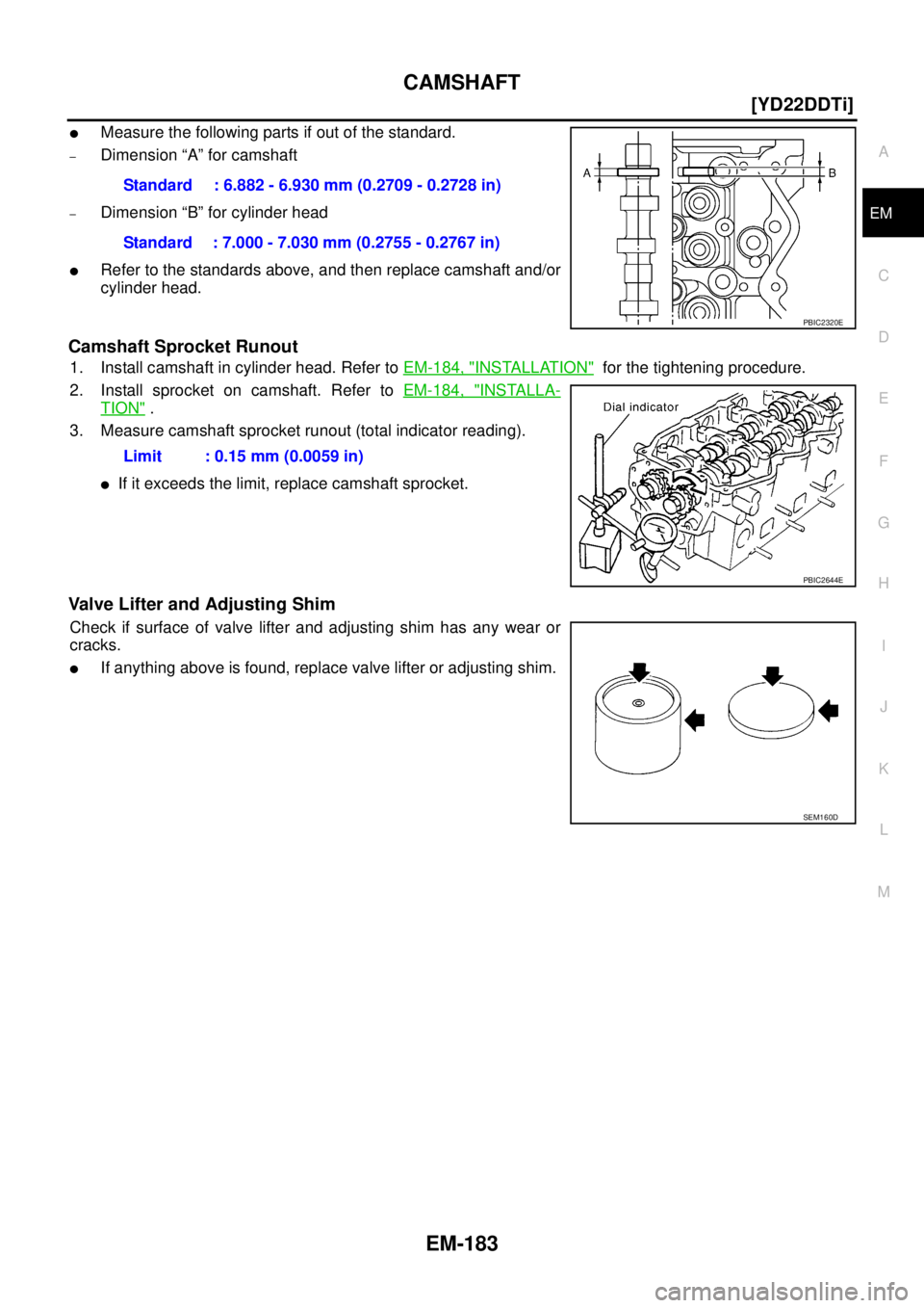
�Measure the following parts if out of the standard.
–Dimension “A” for camshaft
–Dimension “B” for cylinder head
�Refer to the standards above, and then replace camshaft and/or
cylinder head.
Camshaft Sprocket Runout
1. Install camshaft in cylinder head. Refer to EM-184, "INSTALLATION" for the tightening procedure.
2. Install sprocket on camshaft. Refer to EM-184, "
INSTALLA-
TION" .
3. Measure camshaft sprocket runout (total indicator reading).
�If it exceeds the limit, replace camshaft sprocket.
Valve Lifter and Adjusting Shim
Check if surface of valve lifter and adjusting shim has any wear or
cracks.
�If anything above is found, replace valve lifter or adjusting shim. Standard : 6.882 - 6.930 mm (0.2709 - 0.2728 in)
Standard : 7.000 - 7.030 mm (0.2755 - 0.2767 in)
PBIC2320E
Limit : 0.15 mm (0.0059 in)
PBIC2644E
SEM160D
Page 238 of 4555
![NISSAN X-TRAIL 2005 Service Repair Manual EM-184
[YD22DDTi]
CAMSHAFT
Valve Lifter Clearance
VALVE LIFTER OUTER DIAMETER
�Measure the outer diameter of the valve lifter with the microme-
ter.
VALVE LIFTER HOLE DIAMETER
�Measure the hole diam](/manual-img/5/57403/w960_57403-237.png "NISSAN X-TRAIL 2005 Service Repair Manual EM-184
[YD22DDTi]
CAMSHAFT
Valve Lifter Clearance
VALVE LIFTER OUTER DIAMETER
�Measure the outer diameter of the valve lifter with the microme-
ter.
VALVE LIFTER HOLE DIAMETER
�Measure the hole diam")
EM-184
[YD22DDTi]
CAMSHAFT
Valve Lifter Clearance
VALVE LIFTER OUTER DIAMETER
�Measure the outer diameter of the valve lifter with the microme-
ter.
VALVE LIFTER HOLE DIAMETER
�Measure the hole diameter of the cylinder head valve lifter with
the inside micrometer.
VALVE LIFTER CLEARANCE CALCULATIONS
�(Valve lifter clearance) = (Valve lifter hole diameter) – (Valve lifter outer diameter)
�If out of standard, refer to the outer diameter and hole diameter standard values and replace valve lifter
and/or cylinder head.
INSTALLATION
1. Install valve lifter and adjusting shim.
�Make sure that these are installed in the same position as before the removal process.
2. Install camshaft.
�Identify camshafts by the paint position and screw hole at the
rear end.Standard : 29.960 - 29.975 mm (1.1795 - 1.1801 in)
SEM961E
Standard : 30.000 - 30.021 mm (1.1811 - 1.1819 in)
PBIC0367E
Standard : 0.025 - 0.061 mm (0.0010 - 0.0024 in)
Camshaft (right side) Intake manifold side:
Paint is at position A (Brown) without screw hole.
Camshaft (left side) Exhaust manifold side:
Paint is at position B (Pink) with screw hole.
PBIC2496E
Page 239 of 4555
![NISSAN X-TRAIL 2005 Service Repair Manual CAMSHAFT
EM-185
[YD22DDTi]
C
D
E
F
G
H
I
J
K
L
MA
EM
�Install so that knock pins are positioned in the directions
shown in the figure.
NOTE:
Though camshaft does not stop at the location as shown in](/manual-img/5/57403/w960_57403-238.png "NISSAN X-TRAIL 2005 Service Repair Manual CAMSHAFT
EM-185
[YD22DDTi]
C
D
E
F
G
H
I
J
K
L
MA
EM
�Install so that knock pins are positioned in the directions
shown in the figure.
NOTE:
Though camshaft does not stop at the location as shown in")
CAMSHAFT
EM-185
[YD22DDTi]
C
D
E
F
G
H
I
J
K
L
MA
EM
�Install so that knock pins are positioned in the directions
shown in the figure.
NOTE:
Though camshaft does not stop at the location as shown in
the figure, for the placement of cam nose, it is generally
accepted that camshaft is placed at the same direction as
shown in the figure.
3. Install camshaft brackets.
�Completely remove any foreign material on back surfaces of camshaft brackets and top surface of cyl-
inder head.
�Install correctly, identifying brackets by the journal No. and
front mark on top surface.
4. Tighten bolts in the order shown in the figure according to the
following procedure:
a. Tighten all bolts.
�Make sure camshaft thrusting parts (on rear side) securely fit
in their mating parts on the cylinder head.
b. Tighten all bolts.
c. Tighten all bolts.
5. Install camshaft sprockets.
�Camshaft sprockets are commonly used for right side and left side.
�Align camshaft sprocket and knock pin on camshaft, and install.
�Holding the hexagonal part of camshaft with a wrench, tighten bolt securing camshaft sprocket.
6. Before installing spill tube after installing secondary timing chain, check and adjust valve clearance. Refer
to EM-185, "
Valve Clearance" .
7. Hereafter, install in the reverse order of removal.
8. Before starting engine, bleed air from fuel piping. Refer to FL-18, "
Air Bleeding" .
Va l v e C l e a r a n c eEBS00LRS
INSPECTION
�When the camshaft or parts in connection with valves are removed or replaced, and a malfunction has
occurred (poor starting, idling, or other malfunction) due to the misadjustment of the valve clearance,
inspect as follows.
�Inspect and adjust when the engine is cool (at normal temperature).
PBIC2026E
JEM175G
: 2 N·m (0.2 kg-m, 1 ft-lb)
: 6 N·m (0.6 kg-m, 4 ft-lb)
: 12.5 N·m (1.3 kg-m, 9 ft-lb)
JEM160G
![NISSAN X-TRAIL 2005 Service Repair Manual EM-166
[YD22DDTi]
VACUUM PUMP
3. Loosen chain guide mounting bolts. Then remove chain guide.
4. Remove vacuum pump.
CAUTION:
Do not disassemble vacuum pump.
ASSEMBLY
Follow procedure below to instal](/manual-img/5/57403/w960_57403-219.png "NISSAN X-TRAIL 2005 Service Repair Manual EM-166
[YD22DDTi]
VACUUM PUMP
3. Loosen chain guide mounting bolts. Then remove chain guide.
4. Remove vacuum pump.
CAUTION:
Do not disassemble vacuum pump.
ASSEMBLY
Follow procedure below to instal")