Page 244 of 4555
![NISSAN X-TRAIL 2005 Service Repair Manual EM-190
[YD22DDTi]
OIL SEAL
OIL SEALPFP:12279
Removal and Installation of Valve Oil SealEBS01FBM
REMOVAL
1. Remove camshafts. Refer toEM-180, "Removal and Installation" .
2. Remove adjusting shims an](/manual-img/5/57403/w960_57403-243.png "NISSAN X-TRAIL 2005 Service Repair Manual EM-190
[YD22DDTi]
OIL SEAL
OIL SEALPFP:12279
Removal and Installation of Valve Oil SealEBS01FBM
REMOVAL
1. Remove camshafts. Refer toEM-180, \"Removal and Installation\" .
2. Remove adjusting shims an")
EM-190
[YD22DDTi]
OIL SEAL
OIL SEALPFP:12279
Removal and Installation of Valve Oil SealEBS01FBM
REMOVAL
1. Remove camshafts. Refer toEM-180, "Removal and Installation" .
2. Remove adjusting shims and valve lifters. Refer to EM-180, "
Removal and Installation" .
�Check the installation positions, and keep them to avoid being confused.
3. Rotate crankshaft, and set piston whose valve oil seal is to be removed to TDC. This will prevent valve
from dropping into cylinder.
4. Remove valve collet.
�Compress the valve spring with valve spring compressor,
attachment and adapter (special service tool). Remove valve
collet with a magnet hand.
CAUTION:
When working, be careful not to damage valve lifter holes.
5. Remove valve spring retainer and valve spring.
6. Remove valve oil seal with the valve oil seal puller (special ser-
vice tool).
INSTALLATION
1. Apply new engine oil to valve oil seal joint surface and seal lip.
2. Using the valve oil seal drift (special service tool), install valve oil
seals referring to the dimension shown in the figure.
3. Install in the reverse order of removal.
PBIC2388E
JEM153G
JEM165G
Page 247 of 4555
![NISSAN X-TRAIL 2005 Service Repair Manual SECONDARY TIMING CHAIN
EM-193
[YD22DDTi]
C
D
E
F
G
H
I
J
K
L
MA
EM
SECONDARY TIMING CHAINPFP:13028
Removal and InstallationEBS00LRT
CAUTION:
�After removing timing chain, do not turn crankshaft and](/manual-img/5/57403/w960_57403-246.png "NISSAN X-TRAIL 2005 Service Repair Manual SECONDARY TIMING CHAIN
EM-193
[YD22DDTi]
C
D
E
F
G
H
I
J
K
L
MA
EM
SECONDARY TIMING CHAINPFP:13028
Removal and InstallationEBS00LRT
CAUTION:
�After removing timing chain, do not turn crankshaft and")
SECONDARY TIMING CHAIN
EM-193
[YD22DDTi]
C
D
E
F
G
H
I
J
K
L
MA
EM
SECONDARY TIMING CHAINPFP:13028
Removal and InstallationEBS00LRT
CAUTION:
�After removing timing chain, do not turn crankshaft and camshaft separately, or valves will strike
piston heads.
�When installing camshafts, chain tensioners, oil seals, or other sliding parts, lubricate contacting
surfaces with new engine oil.
REMOVAL
�For preparative work for removing/installing secondary timing chain to remove/install fuel pump, refer to
EM-171, "
FUEL PUMP" .
�To prepare for removing/installing secondary timing chain to remove/install camshaft, refer to EM-180,
"Removal and Installation" .
1. Remove engine coolant reservoir tank. Refer to CO-35, "
RADIATOR" .
2. Remove RH engine mounting insulator and bracket. Refer to EM-222, "
ENGINE ASSEMBLY" .
3. Pull power steering reservoir tank out of brackets to move power steering piping. Refer to PS-37,
"HYDRAULIC LINE" .
CAUTION:
To avoid removing power steering reservoir tank out of brackets, move it with power steering pip-
ing aside.
4. Remove front chain case.
1. Chain tensioner 2. Spring 3. Plunger
4. Slack guide 5. Front chain case 6. Rubber washer
7. Tension guide 8. Gasket 9. Secondary timing chain
PBIC2326E
Page 253 of 4555
PRIMARY TIMING CHAIN
EM-199
[YD22DDTi]
C
D
E
F
G
H
I
J
K
L
MA
EM
1. Fuel pump 2. Seal washer 3. Chain tensioner
4. Spring 5. Slack guide 6. Plunger
7. Camshaft sprocket 8. Washer 9. Fuel pump sprocket
PBIC2327E
Page 269 of 4555
CYLINDER HEAD
EM-215
[YD22DDTi]
C
D
E
F
G
H
I
J
K
L
MA
EM
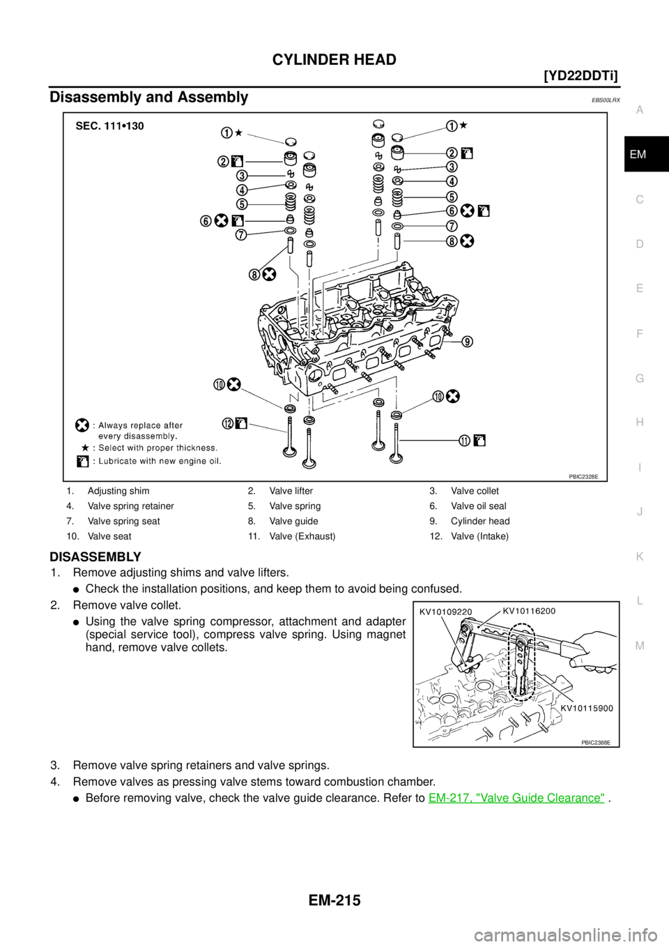
Disassembly and AssemblyEBS00LRX
DISASSEMBLY
1. Remove adjusting shims and valve lifters.
�Check the installation positions, and keep them to avoid being confused.
2. Remove valve collet.
�Using the valve spring compressor, attachment and adapter
(special service tool), compress valve spring. Using magnet
hand, remove valve collets.
3. Remove valve spring retainers and valve springs.
4. Remove valves as pressing valve stems toward combustion chamber.
�Before removing valve, check the valve guide clearance. Refer to EM-217, "Valve Guide Clearance" .
1. Adjusting shim 2. Valve lifter 3. Valve collet
4. Valve spring retainer 5. Valve spring 6. Valve oil seal
7. Valve spring seat 8. Valve guide 9. Cylinder head
10. Valve seat 11. Valve (Exhaust) 12. Valve (Intake)
PBIC2328E
PBIC2388E
Page 270 of 4555
![NISSAN X-TRAIL 2005 Service Repair Manual EM-216
[YD22DDTi]
CYLINDER HEAD
NOTE:
Refer to the figure for intake and exhaust valve positions.
Intake and exhaust valve driving cams are provided alter-
nately for each camshaft.
5. Remove valve](/manual-img/5/57403/w960_57403-269.png "NISSAN X-TRAIL 2005 Service Repair Manual EM-216
[YD22DDTi]
CYLINDER HEAD
NOTE:
Refer to the figure for intake and exhaust valve positions.
Intake and exhaust valve driving cams are provided alter-
nately for each camshaft.
5. Remove valve")
EM-216
[YD22DDTi]
CYLINDER HEAD
NOTE:
Refer to the figure for intake and exhaust valve positions.
Intake and exhaust valve driving cams are provided alter-
nately for each camshaft.
5. Remove valve oil seals using the valve oil seal puller (special
service tool).
6. Remove valve spring seats.
7. When removing valve seats must be replaced. Refer to EM-219, "
Valve Seat Replacement" .
8. When removing valve guides must be replaced. Refer to EM-218, "
Valve Guide Replacement" .
ASSEMBLY
1. Install valve guides if removed. Refer to EM-218, "Valve Guide Replacement" .
2. Install valve seats if removed. Refer to EM-219, "
Valve Seat Replacement" .
3. Using the valve oil seal drift (special service tool), install valve oil
seals referring to the dimension shown in the figure.
4. Install valve spring seats.
5. Install valves.
�Install larger diameter to intake valve side.
�Note that valve layout here is different from that of conven-
tional engine.
6. Install valve spring.
SBIA0196E
JEM153G
JEM165G
SBIA0196E
Page 271 of 4555
![NISSAN X-TRAIL 2005 Service Repair Manual CYLINDER HEAD
EM-217
[YD22DDTi]
C
D
E
F
G
H
I
J
K
L
MA
EM
7. Install valve spring retainers.
8. Using the valve spring compressor, attachment and adapter
(special service tool), compress valve sprin](/manual-img/5/57403/w960_57403-270.png "NISSAN X-TRAIL 2005 Service Repair Manual CYLINDER HEAD
EM-217
[YD22DDTi]
C
D
E
F
G
H
I
J
K
L
MA
EM
7. Install valve spring retainers.
8. Using the valve spring compressor, attachment and adapter
(special service tool), compress valve sprin")
CYLINDER HEAD
EM-217
[YD22DDTi]
C
D
E
F
G
H
I
J
K
L
MA
EM
7. Install valve spring retainers.
8. Using the valve spring compressor, attachment and adapter
(special service tool), compress valve springs.
Then install valve collets using magnet hand.
�After installing valve collets, tap the stem end using the plastic
hammer, and check the installation status.
9. Install valve lifters and adjusting shims to the same positions as before.
INSPECTION AFTER DISASSEMBLY
Valve Dimension
�Check dimensions of each valve. For dimensions, refer to EM-
259, "Valve Dimensions" .
�If dimensions are out of the standard, replace valve.
Valve Guide Clearance
VALVE STEM DIAMETER
�Measure diameter of valve stem with micrometer.
VALVE GUIDE INNER DIAMETER
�Measure inner diameter of valve guide with bore gauge.
VALVE GUIDE CLEARANCE
�(Valve guide clearance) = (Valve guide inner diameter) – (Valve stem diameter).
PBIC2388E
SEM188A
Standard
Intake : 5.965 - 5.980 mm (0.2348 - 0.2354 in)
Exhaust : 5.945 - 5.960 mm (0.2341 - 0.2346 in)
SEM938C
Standard
Intake and Exhaust : 6.000 - 6.018 mm (0.2362 - 0.2369 in)
Valve guide clearance:
Standard
Intake : 0.020 - 0.053 mm (0.0008 - 0.0021 in)
Exhaust : 0.040 - 0.073 mm (0.0016 - 0.0029 in)
Limit
Page 274 of 4555
![NISSAN X-TRAIL 2005 Service Repair Manual EM-220
[YD22DDTi]
CYLINDER HEAD
3. Heat cylinder head to approximately 110 to 130°C (230 to
266°F) by soaking in heated oil.
4. After cooling valve seats sufficiently with dry ice, press fit it to](/manual-img/5/57403/w960_57403-273.png "NISSAN X-TRAIL 2005 Service Repair Manual EM-220
[YD22DDTi]
CYLINDER HEAD
3. Heat cylinder head to approximately 110 to 130°C (230 to
266°F) by soaking in heated oil.
4. After cooling valve seats sufficiently with dry ice, press fit it to")
EM-220
[YD22DDTi]
CYLINDER HEAD
3. Heat cylinder head to approximately 110 to 130°C (230 to
266°F) by soaking in heated oil.
4. After cooling valve seats sufficiently with dry ice, press fit it to cylinder head.
CAUTION:
�Do not touch the cooled valve seats directly by hand.
�Cylinder head contains heat, when working, wear protective equipment to avoid getting burned.
5. Using the valve seat cutter set (commercial service tool), finish
processing referring to the dimensions shown in the figure.
Refer to EM-261, "
Va l v e S e a t" .
CAUTION:
When using the valve seat cutter set, grasp cutter handle
with both hands, press cutter onto contacting face all
around, and cut thoroughly. If cutter is pressed unevenly or
repeatedly, the valve seat surface may be damaged.
6. Using compound, perform valve fitting.
7. Check again to make sure that contacting status is satisfactory.
For details, Refer to EM-219, "
Valve Seat Contact" .
8. Use the depth gauge to measure the distance between the
mounting surface of cylinder head spring seat and the valve
stem end. If the distance is shorter than specified, repeat step 5
above to adjust it. If it is longer, replace valve seat with a new
one.
Valve Spring Square
�Position the try square to valve spring, turn the spring, and mea-
sure the maximum clearance value between top surface of
spring and the try square.
�If it exceeds the limit, replace valve spring.
SEM008A
SEM934C
Valve seat resurface limit “L”:
Intake : 36.53 - 36.98 mm (1.4382 - 1.4559 in)
Exhaust : 36.53 - 37.01 mm (1.4382 - 1.4571 in)
JEM253G
Limit : 1.9 mm (0.075 in)
PBIC0080E
Page 275 of 4555
CYLINDER HEAD
EM-221
[YD22DDTi]
C
D
E
F
G
H
I
J
K
L
MA
EM
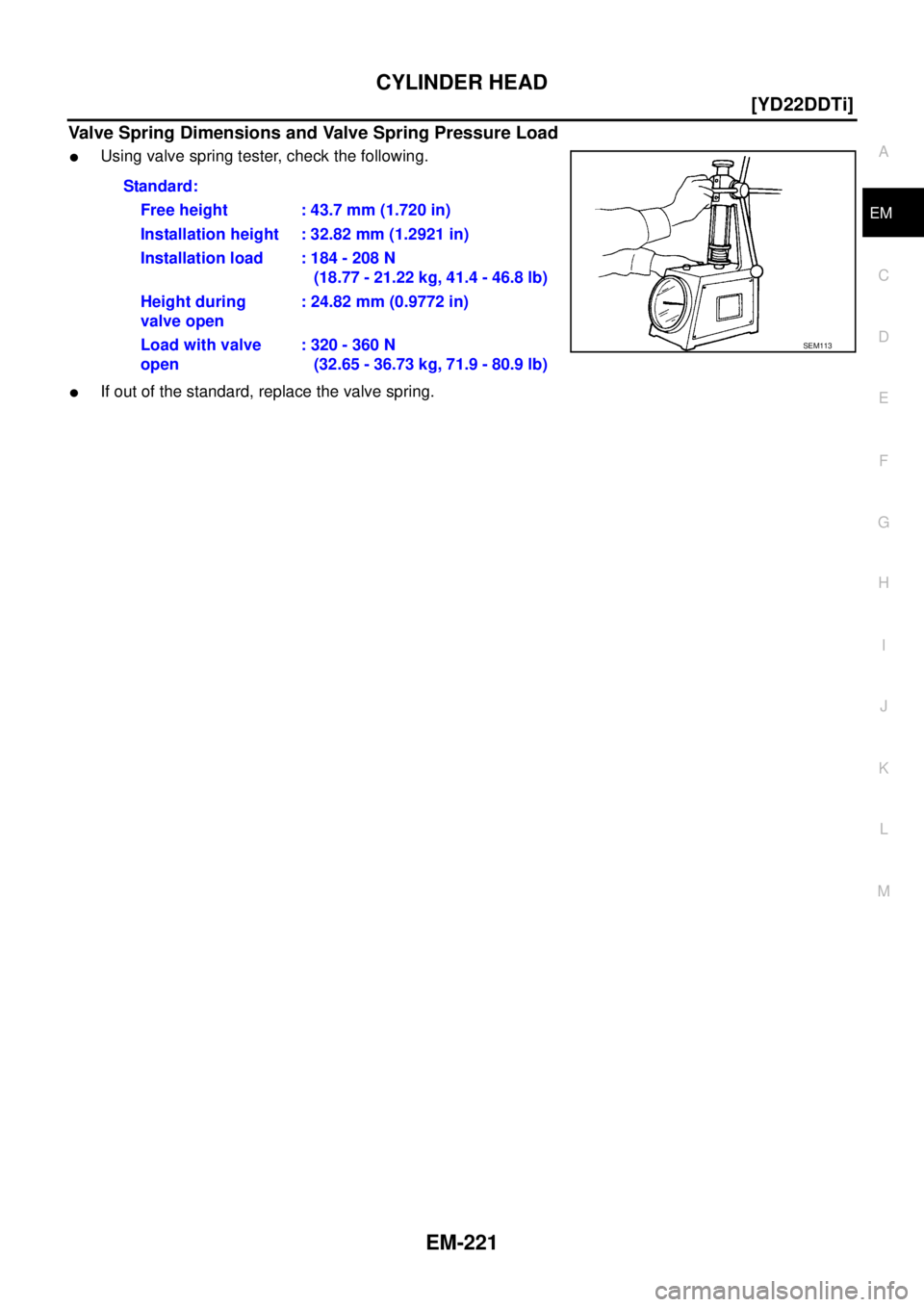
Valve Spring Dimensions and Valve Spring Pressure Load
�Using valve spring tester, check the following.
�If out of the standard, replace the valve spring.Standard:
Free height : 43.7 mm (1.720 in)
Installation height : 32.82 mm (1.2921 in)
Installation load : 184 - 208 N
(18.77 - 21.22 kg, 41.4 - 46.8 lb)
Height during
valve open: 24.82 mm (0.9772 in)
Load with valve
open: 320 - 360 N
(32.65 - 36.73 kg, 71.9 - 80.9 lb)
SEM113
![NISSAN X-TRAIL 2005 Service Repair Manual PRIMARY TIMING CHAIN
EM-199
[YD22DDTi]
C
D
E
F
G
H
I
J
K
L
MA
EM
1. Fuel pump 2. Seal washer 3. Chain tensioner
4. Spring 5. Slack guide 6. Plunger
7. Camshaft sprocket 8. Washer 9. Fuel pump sprock](/manual-img/5/57403/w960_57403-252.png "NISSAN X-TRAIL 2005 Service Repair Manual PRIMARY TIMING CHAIN
EM-199
[YD22DDTi]
C
D
E
F
G
H
I
J
K
L
MA
EM
1. Fuel pump 2. Seal washer 3. Chain tensioner
4. Spring 5. Slack guide 6. Plunger
7. Camshaft sprocket 8. Washer 9. Fuel pump sprock")