Page 130 of 4555
![NISSAN X-TRAIL 2005 Service Repair Manual EM-76
[QR]
CYLINDER HEAD
5. Install valve spring (with valve spring seat).
�Install smaller pitch (valve spring seat side) to cylinder head
side.
�Confirm identification color of valve spring.
6. In](/manual-img/5/57403/w960_57403-129.png "NISSAN X-TRAIL 2005 Service Repair Manual EM-76
[QR]
CYLINDER HEAD
5. Install valve spring (with valve spring seat).
�Install smaller pitch (valve spring seat side) to cylinder head
side.
�Confirm identification color of valve spring.
6. In")
EM-76
[QR]
CYLINDER HEAD
5. Install valve spring (with valve spring seat).
�Install smaller pitch (valve spring seat side) to cylinder head
side.
�Confirm identification color of valve spring.
6. Install valve spring retainer.
7. Install valve collet.
�Compress valve spring with a valve spring compressor,
attachment and adapter (special service tool). Install valve
collet with a magnet hand.
CAUTION:
When working, be careful not to damage valve lifter
holes.
�Tap valve stem edge lightly with a plastic hammer after instal-
lation to check its installed condition.
8. Install valve lifter.
9. Install spark plug tube if removed.
�Press-fit it into cylinder head with the following procedure:
a. Remove old thread locking sealant from cylinder head side
installation hole.
b. Apply thread locking sealant all round on spark plug tube within
approximately 12 mm (0.47 in) width from edge of spark plug
tube on the press-fit side.
Use Genuine Thread Locking Sealant or equivalent.
c. Using a drift, press-fit spark plug tube so that height is as same
as “H” shown in figure.
CAUTION:
�When press-fitting, be careful not to deform spark plug tube.
�After press-fitting, wipe off any protruding thread locking sealant on top surface of cylinder
head.
10. Install spark plug with spark plug wrench (commercial service tool).Intake : Blue
Exhaust : Yellow
PBIC0525E
PBIC1791E
Standard press-fit height “H”:
41.2 - 42.2 mm (1.622 - 1.661 in)
PBIC2636E
Page 134 of 4555
![NISSAN X-TRAIL 2005 Service Repair Manual EM-80
[QR]
CYLINDER HEAD
5. Using valve seat cutter set (commercial service tool) or valve
seat grinder, finish valve seat to the specified dimensions. For
dimensions, refer to EM-121, "
Va l v e S](/manual-img/5/57403/w960_57403-133.png "NISSAN X-TRAIL 2005 Service Repair Manual EM-80
[QR]
CYLINDER HEAD
5. Using valve seat cutter set (commercial service tool) or valve
seat grinder, finish valve seat to the specified dimensions. For
dimensions, refer to EM-121, \"
Va l v e S")
EM-80
[QR]
CYLINDER HEAD
5. Using valve seat cutter set (commercial service tool) or valve
seat grinder, finish valve seat to the specified dimensions. For
dimensions, refer to EM-121, "
Va l v e S e a t" .
CAUTION:
When using valve seat cutter, firmly grip the cutter handle
with both hands. Then, press on the contacting surface all
around the circumference to cut in a single drive. Improper
pressure on with the cutter or cutting many different times
may result in stage valve seat.
6. Using compound, grind to adjust valve fitting.
7. Check again for normal contact. Refer to EM-79, "
VALVE SEAT CONTACT" .
VALVE SPRING SQUARENESS
�Set try square along the side of valve spring and rotate the
spring. Measure the maximum clearance between the top of
valve spring and try square.
CAUTION:
Do not remove valve spring seat from valve spring.
�If it exceeds the limit, replace valve spring (with valve spring
seat).
VALVE SPRING DIMENSIONS AND VALVE SPRING PRESSURE LOAD
�Check valve spring pressure with valve spring seat installed at
the specified spring height.
CAUTION:
Do not remove valve spring seat from valve spring.
Standard:
�If the installation load or load with valve open is out of the standard, replace valve spring (with valve spring
seat).
SEM934C
Limit: 1.9 mm (0.075 in)
PBIC0080E
SEM113
Items Intake Exhaust
Free height 44.84 - 45.34 mm (1.7654 - 1.7850 in) 45.28 - 45.78 mm (1.7827 - 1.8024 in)
Installation height 35.30 mm (1.390 in) 35.30 mm (1.390 in)
Installation load 151 - 175 N (15.4 - 17.8 kg, 34 - 39 lb) 151 - 175 N (15.4 - 17.8 kg, 34 - 39 lb)
Height during valve open 24.94 mm (0.9819 in) 26.39 mm (1.0390 in)
Load with valve open 358 - 408 N (36.5 - 41.6 kg, 80 - 92 lb) 325 - 371 N (33.1 - 37.8 kg, 73 - 83 lb)
Identification color Blue Yellow
Page 173 of 4555
SERVICE DATA AND SPECIFICATIONS (SDS)
EM-119
[QR]
C
D
E
F
G
H
I
J
K
L
MA
EM
Available Valve Lifter
Valve Spring
Thickness mm (in) Identification mark
6.96 (0.2740) 696
6.98 (0.2748) 698
7.00 (0.2756) 700
7.02 (0.2764) 702
7.04 (0.2772) 704
7.06 (0.2780) 706
7.08 (0.2787) 708
7.10 (0.2795) 710
7.12 (0.2803) 712
7.14 (0.2811) 714
7.16 (0.2819) 716
7.18 (0.2827) 718
7.20 (0.2835) 720
7.22 (0.2843) 722
7.24 (0.2850) 724
7.26 (0.2858) 726
7.28 (0.2866) 728
7.30 (0.2874) 730
7.32 (0.2882) 732
7.34 (0.2890) 734
7.36 (0.2898) 736
7.38 (0.2906) 738
7.40 (0.2913) 740
7.42 (0.2921) 742
744 (0.2929) 744
7.46 (0.2937) 746
KBIA0119E
Free height
mm (in) StandardIntake 44.84 - 45.34 (1.7654 - 1.7850)
Exhaust 45.28 - 45.78 (1.7827 - 1.8024)
Pressure
N (kg, lb) at height mm (in)Standard Intake and exhaust 151 - 175 (15.4 - 17.8, 34 - 39) at 35.30 (1.390)
Squareness mm (in) Limit 1.9 (0.075)
Page 187 of 4555
PREPARATION
EM-133
[YD22DDTi]
C
D
E
F
G
H
I
J
K
L
MA
EM
KV101056S0
Ring gear stopper
1. KV10105630
Adapter
2. KV10105610
PlatePreventing crankshaft from rotating
a: 3 (0.12)
b: 6.4 (0.252)
c: 2.8 (0.110)
d: 6.6 (0.260)
e: 107 (4.21)
f: 14 (0.55)
g: 20 (0.79)
h: 14 (0.55) dia.
Unit: mm (in)
KV101151S0
Lifter stopper set
1. KV10115110
Camshaft pliers
2. KV10115120
Lifter stopperChanging adjusting shim
KV10116200
Valve spring compressor
1. KV10115900
Attachment
2. KV10109220
AdapterDisassembling and assembling valve
mechanism
Part (1) is a component of KV10116200, but
Part (2) is not so.
ST16610001
Pilot bushing pullerRemoving crankshaft pilot bushing
KV10111100
Seal cutterRemoving steel oil pan and rear chain case,
etc.
WS39930000
Tube presserPressing the tube of liquid gasket
KV10112100
Angle wrenchTightening bolts for bearing cap, cylinder
head, etc. Tool number
Tool nameDescription
NT617
NT041
PBIC1650E
NT045
NT046
NT052
NT014
Page 221 of 4555
INJECTION TUBE AND FUEL INJECTOR
EM-167
[YD22DDTi]
C
D
E
F
G
H
I
J
K
L
MA
EM
INJECTION TUBE AND FUEL INJECTORPFP:00018
Removal and InstallationEBS00LRO
REMOVAL
1. Remove charge air cooler. Refer to EM-144, "Removal and Installation" .
2. Disconnect harness connector from fuel injector.
3. Remove spill hose. Refer to EM-146, "
INTAKE MANIFOLD" .
4. Remove injection tubes as follows:
a. Put a paint mark or tag on injection tubes to identify each cylinder.
�Use a fuel-resistant method.
1. Spill tube 2. Eye-bolt 3. Spill tube gasket
4. Nozzle support 5. Pin 6. Fuel injector
7. O-ring 8. Nozzle gasket 9. Washer
10. Nozzle oil seal 11. Rocker cover 12. Injection tube No. 1
13. Injection tube No. 2 14. Injection tube No. 3 15. Injection tube No. 4
16. Insert rubber 17. Injection tube center 18. Clip
19. Washer 20. Spring washer 21. Fuel rail
22. Fuel rail gasket 23. Fuel hose
PBIC2584E
Page 224 of 4555
EM-170
[YD22DDTi]
INJECTION TUBE AND FUEL INJECTOR
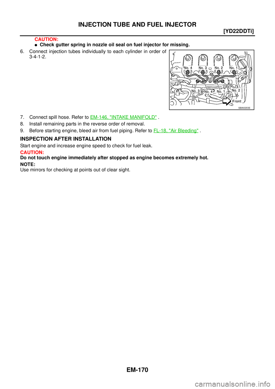
CAUTION:
�Check gutter spring in nozzle oil seal on fuel injector for missing.
6. Connect injection tubes individually to each cylinder in order of
3-4-1-2.
7. Connect spill hose. Refer to EM-146, "
INTAKE MANIFOLD" .
8. Install remaining parts in the reverse order of removal.
9. Before starting engine, bleed air from fuel piping. Refer to FL-18, "
Air Bleeding" .
INSPECTION AFTER INSTALLATION
Start engine and increase engine speed to check for fuel leak.
CAUTION:
Do not touch engine immediately after stopped as engine becomes extremely hot.
NOTE:
Use mirrors for checking at points out of clear sight.
SBIA0203E
Page 242 of 4555
![NISSAN X-TRAIL 2005 Service Repair Manual EM-188
[YD22DDTi]
CAMSHAFT
3. Grip camshaft with the camshaft pliers (special service tool),
then using camshaft as a support point, push adjusting shim
downward to compress valve spring.
CAUTION:
D](/manual-img/5/57403/w960_57403-241.png "NISSAN X-TRAIL 2005 Service Repair Manual EM-188
[YD22DDTi]
CAMSHAFT
3. Grip camshaft with the camshaft pliers (special service tool),
then using camshaft as a support point, push adjusting shim
downward to compress valve spring.
CAUTION:
D")
EM-188
[YD22DDTi]
CAMSHAFT
3. Grip camshaft with the camshaft pliers (special service tool),
then using camshaft as a support point, push adjusting shim
downward to compress valve spring.
CAUTION:
Do not damage camshaft, cylinder head and the outer cir-
cumference of valve lifter.
4. With valve spring in a compressed state, remove the camshaft
pliers (special service tool) by securely setting the outer circum-
ference of the valve lifter with the end of the lifter stopper (spe-
cial service tool).
�Hold the lifter stopper by hand until the shim is removed.
CAUTION:
Do not retrieve the camshaft pliers forcefully, as cam-
shaft will be damaged.
5. Move the round hole of adjusting shim to the front with the very
thin screwdriver or like that.
�When adjusting shim on valve lifter will not rotate smoothly,
restart from step 3 to release the end of the lifter stopper (spe-
cial service tool) from touching adjusting shim.
6. Remove adjusting shim from valve lifter by blowing air through
the round hole of the adjusting shim with the air gun.
CAUTION:
To prevent any remaining engine oil from being blown
around, thoroughly wipe the area clean and wear protective
goggles.
7. Remove adjusting shim by using the magnet hand.
8. Measure the thickness of adjusting shim using the micrometer.
�Measure near the center of the shim (the part that touches
camshaft).
PBIC2321E
PBIC2322E
PBIC2323E
PBIC2324E
FEM032
Page 243 of 4555
![NISSAN X-TRAIL 2005 Service Repair Manual CAMSHAFT
EM-189
[YD22DDTi]
C
D
E
F
G
H
I
J
K
L
MA
EM
9. Select the new adjusting shim from the following methods.
�New adjusting shims have the thickness stamped on the rear
side.
�Shims are availab](/manual-img/5/57403/w960_57403-242.png "NISSAN X-TRAIL 2005 Service Repair Manual CAMSHAFT
EM-189
[YD22DDTi]
C
D
E
F
G
H
I
J
K
L
MA
EM
9. Select the new adjusting shim from the following methods.
�New adjusting shims have the thickness stamped on the rear
side.
�Shims are availab")
CAMSHAFT
EM-189
[YD22DDTi]
C
D
E
F
G
H
I
J
K
L
MA
EM
9. Select the new adjusting shim from the following methods.
�New adjusting shims have the thickness stamped on the rear
side.
�Shims are available in 33 size from 2.10 mm (0.0827 in) to
2.74 mm (0.1079 in), in steps of 0.02 mm (0.0008 in).
10. Fit the selected adjusting shim to valve lifter.
CAUTION:
Place the stamped side of adjusting shim to valve lifter.
11. Compress valve spring using the camshaft pliers (special service tool: KV10115110) and remove the lifter
stopper (special service tool).
12. Rotate crankshaft 2 to 3 turns by hand.
13. Confirm that the valve clearance is within the specification. Refer to EM-185, "
INSPECTION" .
14. Install remaining parts in the reverse order of removal. Refer to EM-184, "
INSTALLATION" .
15. Warm up the engine, and check for unusual noise and vibration.Calculation method of the adjusting shim thickness:
R = Thickness of removed shim
N = Thickness of new shim
M = Measured valve clearance
Intake
N = R + [M - 0.28 mm (0.0010 in)]
Exhaust
N = R + [M - 0.30 mm (0.0118 in)]
Stamped mark Shim thickness mm (in)
2.10
2.12
·
·
·
2.74 2.10 (0.0827)
2.12 (0.0835)
·
·
·
2.74 (0.1079)
JEM184G
PBIC2325E
![NISSAN X-TRAIL 2005 Service Repair Manual SERVICE DATA AND SPECIFICATIONS (SDS)
EM-119
[QR]
C
D
E
F
G
H
I
J
K
L
MA
EM
Available Valve Lifter
Valve Spring
Thickness mm (in) Identification mark
6.96 (0.2740) 696
6.98 (0.2748) 698
7.00 (0.2756](/manual-img/5/57403/w960_57403-172.png "NISSAN X-TRAIL 2005 Service Repair Manual SERVICE DATA AND SPECIFICATIONS (SDS)
EM-119
[QR]
C
D
E
F
G
H
I
J
K
L
MA
EM
Available Valve Lifter
Valve Spring
Thickness mm (in) Identification mark
6.96 (0.2740) 696
6.98 (0.2748) 698
7.00 (0.2756")
![NISSAN X-TRAIL 2005 Service Repair Manual PREPARATION
EM-133
[YD22DDTi]
C
D
E
F
G
H
I
J
K
L
MA
EM
KV101056S0
Ring gear stopper
1. KV10105630
Adapter
2. KV10105610
PlatePreventing crankshaft from rotating
a: 3 (0.12)
b: 6.4 (0.252)
c: 2.8 (0](/manual-img/5/57403/w960_57403-186.png "NISSAN X-TRAIL 2005 Service Repair Manual PREPARATION
EM-133
[YD22DDTi]
C
D
E
F
G
H
I
J
K
L
MA
EM
KV101056S0
Ring gear stopper
1. KV10105630
Adapter
2. KV10105610
PlatePreventing crankshaft from rotating
a: 3 (0.12)
b: 6.4 (0.252)
c: 2.8 (0")
![NISSAN X-TRAIL 2005 Service Repair Manual INJECTION TUBE AND FUEL INJECTOR
EM-167
[YD22DDTi]
C
D
E
F
G
H
I
J
K
L
MA
EM
INJECTION TUBE AND FUEL INJECTORPFP:00018
Removal and InstallationEBS00LRO
REMOVAL
1. Remove charge air cooler. Refer to](/manual-img/5/57403/w960_57403-220.png "NISSAN X-TRAIL 2005 Service Repair Manual INJECTION TUBE AND FUEL INJECTOR
EM-167
[YD22DDTi]
C
D
E
F
G
H
I
J
K
L
MA
EM
INJECTION TUBE AND FUEL INJECTORPFP:00018
Removal and InstallationEBS00LRO
REMOVAL
1. Remove charge air cooler. Refer to")