Page 348 of 4555
LU-26
[YD22DDTi]
OIL FILTER BRACKET
OIL FILTER BRACKETPFP:15238
Removal and Installation (TYPE A)EBS00BL8
REMOVAL
CAUTION:
Be careful not to get burned when engine is hot.
1. Remove RH engine undercover.
2. Remove oil filter. Refer to LU-23, "
Removal and Installation (TYPE A)" .
3. Remove oil filter bracket.
INSTALLATION
Install all removed parts in the reverse order of removal.
�Insert the top mounting bolt to oil filter bracket beforehand, and set oil filter bracket to the installation loca-
tion.
INSPECTION AFTER INSTALLATION
1. After warming up engine, check there is no leaks of engine oil.
2. Stop engine and wait for 10 minutes.
3. Check the engine oil level and adjust engine oil. Refer to LU-20, "
ENGINE OIL" .
1. Oil pump housing 2. Gasket 3. Oil filter bracket
4. Oil filter
PBIC2380E
Page 349 of 4555
OIL FILTER BRACKET
LU-27
[YD22DDTi]
C
D
E
F
G
H
I
J
K
L
MA
LU
Removal and Installation (TYPE B)EBS011WJ
REMOVAL
CAUTION:
Be careful not to get burned when engine is hot.
1. Remove RH engine undercover.
2. Remove oil filter. Refer to LU-24, "
Removal and Installation (TYPE B)" .
3. Remove oil filter bracket.
INSTALLATION
Install all removed parts in the reverse order of removal.
�Insert the top mounting bolt to oil filter bracket beforehand, and set oil filter bracket to the installation loca-
tion.
INSPECTION AFTER INSTALLATION
1. After warming up engine, check there is no leaks of engine oil.
2. Stop engine and wait for 10 minutes.
3. Check the engine oil level and adjust engine oil. Refer to LU-20, "
ENGINE OIL" .
1. Oil pump housing 2. Gasket 3. Oil filler bracket
4. Oil filler 5. O-ring 6. Oil filter body
PBIC2537E
Page 355 of 4555
![NISSAN X-TRAIL 2005 Service Repair Manual SERVICE DATA AND SPECIFICATIONS (SDS)
LU-33
[YD22DDTi]
C
D
E
F
G
H
I
J
K
L
MA
LU
SERVICE DATA AND SPECIFICATIONS (SDS)PFP:00030
Standard and LimitEBS00CTZ
OIL PRESSURE
OIL PUMP
Unit: mm (in)
REGULAT](/manual-img/5/57403/w960_57403-354.png "NISSAN X-TRAIL 2005 Service Repair Manual SERVICE DATA AND SPECIFICATIONS (SDS)
LU-33
[YD22DDTi]
C
D
E
F
G
H
I
J
K
L
MA
LU
SERVICE DATA AND SPECIFICATIONS (SDS)PFP:00030
Standard and LimitEBS00CTZ
OIL PRESSURE
OIL PUMP
Unit: mm (in)
REGULAT")
SERVICE DATA AND SPECIFICATIONS (SDS)
LU-33
[YD22DDTi]
C
D
E
F
G
H
I
J
K
L
MA
LU
SERVICE DATA AND SPECIFICATIONS (SDS)PFP:00030
Standard and LimitEBS00CTZ
OIL PRESSURE
OIL PUMP
Unit: mm (in)
REGULATOR VALVE
Unit: mm (in)
OIL CAPACITY (APPROXIMATE)
Unit: · (Imp qt)
Tightening TorqueEBS00B0F
Unit: N·m (kg-m, ft-lb)
Unit: N·m (kg-m, in-lb)* Engine speed rpm
Approximate discharge pressure kPa (bar, kg/cm
2 , psi)
Idle speed
2,000140 (1.40, 1.43, 20.3) or more
270 (2.70, 2.75, 39.2) or more
Oil pump housing to outer rotor radial clearance 0.114 - 0.260 (0.0045 - 0.0102)
Inner rotor to outer rotor tip clearance Below 0.18 (0.0071)
Oil pump housing to inner rotor side clearance 0.050 - 0.090 (0.0020 - 0.0035)
Oil pump housing to outer rotor side clearance 0.030 - 0.190 (0.0012 - 0.0075)
Inner rotor to oil pump housing clearance 0.045 - 0.091 (0.0018 - 0.0036)
Regulator valve to valve hole clearance 0.040 - 0.097 (0.0016 - 0.0038)
With oil filter change 5.2 (4-5/8 Imp qt)
Without oil filter change 4.9 (4-3/8 Imp qt)
Dry engine (engine overhaul) 6.3 (5-1/2 Imp qt)
Oil pressure switch15 (1.5, 11)
Oil pan drain plug34 (3.5, 25)
Oil filter bracket21.5 (2.2, 16)
Oil filter (TYPE A)18 (1.8, 13)
Oil filler body (TYPE B) 22 (2.2, 16)
Oil pump cover Bolts 6.9 (0.7, 61)*
Screws 6.9 (0.7, 61)*
Regulator plug54 (5.5, 40)
Water hose connector 23.6 (2.4, 17)
Oil cooler24.5 (2.5, 18)
Page 491 of 4555
![NISSAN X-TRAIL 2005 Service Repair Manual TROUBLE DIAGNOSIS
EC-87
[QR (WITH EURO-OBD)]
C
D
E
F
G
H
I
J
K
L
MA
EC
1 - 6: The numbers refer to the order of inspection.Va l v e
mecha-
nismTiming chain
55555 55 5EM-46
CamshaftEM-56
Intake val](/manual-img/5/57403/w960_57403-490.png "NISSAN X-TRAIL 2005 Service Repair Manual TROUBLE DIAGNOSIS
EC-87
[QR (WITH EURO-OBD)]
C
D
E
F
G
H
I
J
K
L
MA
EC
1 - 6: The numbers refer to the order of inspection.Va l v e
mecha-
nismTiming chain
55555 55 5EM-46
CamshaftEM-56
Intake val")
TROUBLE DIAGNOSIS
EC-87
[QR (WITH EURO-OBD)]
C
D
E
F
G
H
I
J
K
L
MA
EC
1 - 6: The numbers refer to the order of inspection.Va l v e
mecha-
nismTiming chain
55555 55 5EM-46
CamshaftEM-56
Intake valve timing controlEM-46
Intake valve
3EM-70
Exhaust valve
Exhaust Exhaust manifold/Tube/Muffler/
Gasket
55555 55 5EM-25
, EX-
2Three way catalyst
Lubrica-
tionOil pan/Oil strainer/Oil pump/Oil
filter/Oil gallery
55555 55 52EM-27
, LU-
13 , LU-10 ,
LU-5
Oil level (Low)/Filthy oilLU-7
Cooling Radiator/Hose/Radiator filler cap
55555 55 25CO-12
Thermostat 5CO-23
Water pumpCO-21
Water galleryCO-7
Cooling fan 5CO-19
Coolant level (low)/Contaminated
coolantCO-9
NATS (Nissan Anti-theft System) 1 1EC-64 or
BL-108
SYMPTOM
Reference
page
HARD/NO START/RESTART (EXCP. HA)
ENGINE STALL
HESITATION/SURGING/FLAT SPOT
SPARK KNOCK/DETONATION
LACK OF POWER/POOR ACCELERATION
HIGH IDLE/LOW IDLE
ROUGH IDLE/HUNTING
IDLING VIBRATION
SLOW/NO RETURN TO IDLE
OVERHEATS/WATER TEMPERATURE HIGH
EXCESSIVE FUEL CONSUMPTION
EXCESSIVE OIL CONSUMPTION
BATTERY DEAD (UNDER CHARGE)
Warranty symptom code AA AB AC AD AE AF AG AH AJ AK AL AM HA
Page 991 of 4555
![NISSAN X-TRAIL 2005 Service Repair Manual TROUBLE DIAGNOSIS
EC-587
[QR (WITHOUT EURO-OBD)]
C
D
E
F
G
H
I
J
K
L
MA
EC
1 - 6: The numbers refer to the order of inspection.Va l v e
mecha-
nismTiming chain
55555 55 5EM-46
CamshaftEM-56
Intake](/manual-img/5/57403/w960_57403-990.png "NISSAN X-TRAIL 2005 Service Repair Manual TROUBLE DIAGNOSIS
EC-587
[QR (WITHOUT EURO-OBD)]
C
D
E
F
G
H
I
J
K
L
MA
EC
1 - 6: The numbers refer to the order of inspection.Va l v e
mecha-
nismTiming chain
55555 55 5EM-46
CamshaftEM-56
Intake")
TROUBLE DIAGNOSIS
EC-587
[QR (WITHOUT EURO-OBD)]
C
D
E
F
G
H
I
J
K
L
MA
EC
1 - 6: The numbers refer to the order of inspection.Va l v e
mecha-
nismTiming chain
55555 55 5EM-46
CamshaftEM-56
Intake valve timing controlEM-46
Intake valve
3EM-70
Exhaust valve
Exhaust Exhaust manifold/Tube/Muffler/
Gasket
55555 55 5EM-25
, EX-
2Three way catalyst
Lubrica-
tionOil pan/Oil strainer/Oil pump/Oil
filter/Oil gallery
55555 55 52EM-27
, LU-
13 , LU-10 ,
LU-5
Oil level (Low)/Filthy oilLU-7
Cooling Radiator/Hose/Radiator filler cap
55555 55 25CO-12
Thermostat 5CO-23
Water pumpCO-21
Water galleryCO-7
Cooling fan 5CO-19
Coolant level (low)/Contaminated
coolantCO-9
NATS (Nissan Anti-theft System) 1 1EC-567 or
BL-108
SYMPTOM
Reference
page
HARD/NO START/RESTART (EXCP. HA)
ENGINE STALL
HESITATION/SURGING/FLAT SPOT
SPARK KNOCK/DETONATION
LACK OF POWER/POOR ACCELERATION
HIGH IDLE/LOW IDLE
ROUGH IDLE/HUNTING
IDLING VIBRATION
SLOW/NO RETURN TO IDLE
OVERHEATS/WATER TEMPERATURE HIGH
EXCESSIVE FUEL CONSUMPTION
EXCESSIVE OIL CONSUMPTION
BATTERY DEAD (UNDER CHARGE)
Warranty symptom code AA AB AC AD AE AF AG AH AJ AK AL AM HA
Page 2116 of 4555
FL-10
[QR]
FUEL LEVEL SENSOR UNIT, FUEL FILTER AND FUEL PUMP ASSEMBLY
�Visually check O-ring, mounting parts and mating parts for foreign materials and flaws.
�Before installing, lubricate new engine oil.
�To avoid damage, do not apply an excessive force (pulling or stretching).
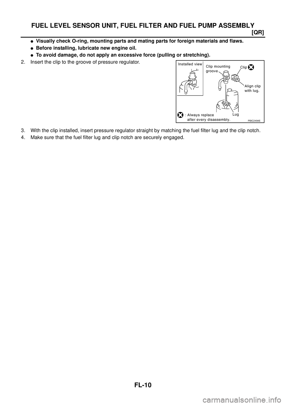
2. Insert the clip to the groove of pressure regulator.
3. With the clip installed, insert pressure regulator straight by matching the fuel filter lug and the clip notch.
4. Make sure that the fuel filter lug and clip notch are securely engaged.
PBIC2494E
Page 2479 of 4555
TROUBLE DIAGNOSES FOR SYMPTOMS
AT-215
[EURO-OBD]
D
E
F
G
H
I
J
K
L
MA
B
AT
5. CHECK A/T FLUID CONDITION
1. Remove oil pan. Refer to AT- 4 0 4 , "
COMPONENTS" .
2. Check A/T fluid condition. Refer to AT- 6 4 , "
FLUID CONDITION
CHECK" .
OK or NG
OK >> GO TO 6.
NG >> GO TO 8.
6. DETECT MALFUNCTIONING ITEM
1. Remove control valve assembly. Refer to AT- 4 0 4 , "
Control Valve Assembly and Accumulators" .
2. Check the following items:
–Shift valve A
–Shift valve B
–Shift solenoid valve A
–Shift solenoid valve B
–Pilot valve
–Pilot filter
OK or NG
OK >> GO TO 7.
NG >> Repair or replace damaged parts.
7. CHECK SYMPTOM
Check again. Refer to AT- 7 8 , "
Cruise Test — Part 1" .
OK or NG
OK >>INSPECTION END
NG >> 1. Perform TCM input/output signal inspection. Refer to AT- 9 4 , "
TCM Terminals and Reference
Va l u e" .
2. If NG, recheck TCM pin terminals for damage or loose connection with harness connector.
SAT171B
Page 2480 of 4555
AT-216
[EURO-OBD]
TROUBLE DIAGNOSES FOR SYMPTOMS
8. DETECT MALFUNCTIONING ITEM
1. Remove control valve assembly. Refer to AT- 4 0 4 , "
Control Valve Assembly and Accumulators" .
2. Check the following items:
–Shift valve A
–Shift valve B
–Shift solenoid valve A
–Shift solenoid valve B
–Pilot valve
–Pilot filter
3. Disassemble A/T. Refer to AT- 4 2 4 , "
Disassembly" .
4. Check the following items:
–Forward clutch. Refer to AT- 4 7 5 , "Forward and Overrun Clutches" .
–Forward one-way clutch assembly. Refer to AT- 4 2 4 , "Disassembly" .
–High clutch assembly. Refer to AT- 4 6 9 , "High Clutch" .
–Torque converter. Refer to AT- 4 2 4 , "Disassembly" .
–Oil pump assembly. Refer to AT- 4 4 3 , "Oil Pump" .
–Reverse clutch assembly. Refer to AT- 4 6 4 , "Reverse Clutch" .
–Low & reverse clutch assembly
OK or NG
OK >> GO TO 7.
NG >> Repair or replace damaged parts.
![NISSAN X-TRAIL 2005 Service Repair Manual LU-26
[YD22DDTi]
OIL FILTER BRACKET
OIL FILTER BRACKETPFP:15238
Removal and Installation (TYPE A)EBS00BL8
REMOVAL
CAUTION:
Be careful not to get burned when engine is hot.
1. Remove RH engine under](/manual-img/5/57403/w960_57403-347.png "NISSAN X-TRAIL 2005 Service Repair Manual LU-26
[YD22DDTi]
OIL FILTER BRACKET
OIL FILTER BRACKETPFP:15238
Removal and Installation (TYPE A)EBS00BL8
REMOVAL
CAUTION:
Be careful not to get burned when engine is hot.
1. Remove RH engine under")
![NISSAN X-TRAIL 2005 Service Repair Manual OIL FILTER BRACKET
LU-27
[YD22DDTi]
C
D
E
F
G
H
I
J
K
L
MA
LU
Removal and Installation (TYPE B)EBS011WJ
REMOVAL
CAUTION:
Be careful not to get burned when engine is hot.
1. Remove RH engine underco](/manual-img/5/57403/w960_57403-348.png "NISSAN X-TRAIL 2005 Service Repair Manual OIL FILTER BRACKET
LU-27
[YD22DDTi]
C
D
E
F
G
H
I
J
K
L
MA
LU
Removal and Installation (TYPE B)EBS011WJ
REMOVAL
CAUTION:
Be careful not to get burned when engine is hot.
1. Remove RH engine underco")
![NISSAN X-TRAIL 2005 Service Repair Manual TROUBLE DIAGNOSES FOR SYMPTOMS
AT-215
[EURO-OBD]
D
E
F
G
H
I
J
K
L
MA
B
AT
5. CHECK A/T FLUID CONDITION
1. Remove oil pan. Refer to AT- 4 0 4 , "
COMPONENTS" .
2. Check A/T fluid condition. Refer t](/manual-img/5/57403/w960_57403-2478.png "NISSAN X-TRAIL 2005 Service Repair Manual TROUBLE DIAGNOSES FOR SYMPTOMS
AT-215
[EURO-OBD]
D
E
F
G
H
I
J
K
L
MA
B
AT
5. CHECK A/T FLUID CONDITION
1. Remove oil pan. Refer to AT- 4 0 4 , \"
COMPONENTS\" .
2. Check A/T fluid condition. Refer t")
![NISSAN X-TRAIL 2005 Service Repair Manual AT-216
[EURO-OBD]
TROUBLE DIAGNOSES FOR SYMPTOMS
8. DETECT MALFUNCTIONING ITEM
1. Remove control valve assembly. Refer to AT- 4 0 4 , "
Control Valve Assembly and Accumulators" .
2. Check the follo](/manual-img/5/57403/w960_57403-2479.png "NISSAN X-TRAIL 2005 Service Repair Manual AT-216
[EURO-OBD]
TROUBLE DIAGNOSES FOR SYMPTOMS
8. DETECT MALFUNCTIONING ITEM
1. Remove control valve assembly. Refer to AT- 4 0 4 , \"
Control Valve Assembly and Accumulators\" .
2. Check the follo")