Page 217 of 4555
![NISSAN X-TRAIL 2005 Service Repair Manual VACUUM PUMP
EM-163
[YD22DDTi]
C
D
E
F
G
H
I
J
K
L
MA
EM
VACUUM PUMPPFP:41920
Removal and InstallationEBS00LRM
INSPECTION BEFORE REMOVAL
1. Disconnect vacuum hose, and connect a vacuum gauge via 3-wa](/manual-img/5/57403/w960_57403-216.png "NISSAN X-TRAIL 2005 Service Repair Manual VACUUM PUMP
EM-163
[YD22DDTi]
C
D
E
F
G
H
I
J
K
L
MA
EM
VACUUM PUMPPFP:41920
Removal and InstallationEBS00LRM
INSPECTION BEFORE REMOVAL
1. Disconnect vacuum hose, and connect a vacuum gauge via 3-wa")
VACUUM PUMP
EM-163
[YD22DDTi]
C
D
E
F
G
H
I
J
K
L
MA
EM
VACUUM PUMPPFP:41920
Removal and InstallationEBS00LRM
INSPECTION BEFORE REMOVAL
1. Disconnect vacuum hose, and connect a vacuum gauge via 3-way connector.
�Disconnect point where vacuum from vacuum pump can be measured directly and install 3-way con-
nector.
2. Start engine and measure generated vacuum at idle speed.
�If out of standard, check for air suction in vacuum route, and measure again.
�If still outside of standard, replace vacuum pump.
REMOVAL
1. Drain engine coolant. Refer to CO-32, "Changing Engine Coolant" .
2. Remove air duct and air cleaner case (upper). Refer to EM-142, "
Removal and Installation" .
3. Remove charge air cooler. Refer to EM-144, "
Removal and Installation" .
4. Disconnect harness connector from fuel injector.
5. Remove injection tubes. Refer to EM-167, "
Removal and Installation" .
6. Remove rocker cover. Refer to EM-178, "
Removal and Installation" .
7. Remove spill tube. Refer to EM-167, "
Removal and Installation" .
8. Remove nozzle support from No. 2 cylinder and No. 2 fuel injector. Refer to EM-167, "
Removal and Instal-
lation" . (To fix the hexagonal portion of the camshaft.)
9. Remove air inlet pipes. Refer to EM-151, "
Removal and Installation" .
1.Vacuum pump and cylinder head rear cover
assembly2. O-ring 3. Cylinder head rear cover plate
4. Camshaft position sensor
PBIC3638E
Standard:
– 86.6 to – 101.3 kPa (– 866 to – 1,013 mbar, – 650 to – 760 mmHg, – 25.59 to – 29.92 inHg)
Page 221 of 4555
INJECTION TUBE AND FUEL INJECTOR
EM-167
[YD22DDTi]
C
D
E
F
G
H
I
J
K
L
MA
EM
INJECTION TUBE AND FUEL INJECTORPFP:00018
Removal and InstallationEBS00LRO
REMOVAL
1. Remove charge air cooler. Refer to EM-144, "Removal and Installation" .
2. Disconnect harness connector from fuel injector.
3. Remove spill hose. Refer to EM-146, "
INTAKE MANIFOLD" .
4. Remove injection tubes as follows:
a. Put a paint mark or tag on injection tubes to identify each cylinder.
�Use a fuel-resistant method.
1. Spill tube 2. Eye-bolt 3. Spill tube gasket
4. Nozzle support 5. Pin 6. Fuel injector
7. O-ring 8. Nozzle gasket 9. Washer
10. Nozzle oil seal 11. Rocker cover 12. Injection tube No. 1
13. Injection tube No. 2 14. Injection tube No. 3 15. Injection tube No. 4
16. Insert rubber 17. Injection tube center 18. Clip
19. Washer 20. Spring washer 21. Fuel rail
22. Fuel rail gasket 23. Fuel hose
PBIC2584E
Page 222 of 4555
EM-168
[YD22DDTi]
INJECTION TUBE AND FUEL INJECTOR
b. Remove injection tubes in order of 2-1-4-3 individually.
CAUTION:
Be careful not to allow leaked fuel to contaminate engine
room. Especially, ensure to keep engine mounting insulator
clear of fuel.
5. Remove nozzle oil seal.
�Using the flat-bladed screwdriver, pry flange to remove oil
seal.
NOTE:
Nozzle oil seal seals between fuel injector and rocker cover. If
only injection tube shall be removed and installed, nozzle oil
seal replacement is not required.
6. Remove rocker cover. Refer to EM-178, "
Removal and Installation" .
7. Remove spill tube mounting bolts and nut.
�Loosen bolts and nut to the reverse order in the figure and
remove them.
CAUTION:
When loosening nut, fix spill tube retaining bolt with span-
ner.
SBIA0203E
PBIC0944E
PBIC3606E
Page 223 of 4555
![NISSAN X-TRAIL 2005 Service Repair Manual INJECTION TUBE AND FUEL INJECTOR
EM-169
[YD22DDTi]
C
D
E
F
G
H
I
J
K
L
MA
EM
8. Remove fuel injector as follows:
a. Remove nozzle support.
b. Remove fuel injector. While rotating it to left and righ](/manual-img/5/57403/w960_57403-222.png "NISSAN X-TRAIL 2005 Service Repair Manual INJECTION TUBE AND FUEL INJECTOR
EM-169
[YD22DDTi]
C
D
E
F
G
H
I
J
K
L
MA
EM
8. Remove fuel injector as follows:
a. Remove nozzle support.
b. Remove fuel injector. While rotating it to left and righ")
INJECTION TUBE AND FUEL INJECTOR
EM-169
[YD22DDTi]
C
D
E
F
G
H
I
J
K
L
MA
EM
8. Remove fuel injector as follows:
a. Remove nozzle support.
b. Remove fuel injector. While rotating it to left and right, raise it to
remove.
CAUTION:
�Handle fuel injector carefully without giving any impact.
�Do not disassemble fuel injector.
c. If nozzle gasket remains in cylinder head, hook it with tip of a
flat-bladed screwdriver and pull it out.
d. Remove O-ring from fuel injector.
INSTALLATION
1. Install fuel injector as follows:
a. Install O-ring and nozzle gasket to fuel injector, and insert them into cylinder head.
b. Tighten injection tubes temporarily in the order of 3-4-1-2.
c. Be sure to fit nozzle support without looseness.
d. Tighten nozzle support bolts.
�Apply engine oil onto threaded parts of bolts and seating areas.
e. Remove injection tubes.
2. Connect spill tube.
�Tighten fixing bolts and nut in numerical order shown in the
figure.
CAUTION:
When tightening nut, fix spill tube retaining bolt with
spanner.
NOTE:
Connection of spill tube gasket may be broken, even if it is
tighten to the specified torque. It does not affect performance.
3. Perform air tightness test for spill tube.
�Connect a handy vacuum pump to spill connector. Make sure
that vacuum is retained while applying following vacuum.
�If outside of standard, reconnect spill tube. (Replace gasket in
this case.)
4. Install rocker cover. Refer to EM-178, "
Removal and Installation"
.
5. Install nozzle oil seal.
�Insert it straight until its flange fully contacts rocker cover.
PBIC0759E
PBIC3606E
Standard:
– 53.3 to – 66.7 kPa (– 533 to – 667 mbar, – 400 to
– 500 mmHg, – 15.75 to – 19.69 inHg)
JEF250Z
Page 224 of 4555
EM-170
[YD22DDTi]
INJECTION TUBE AND FUEL INJECTOR
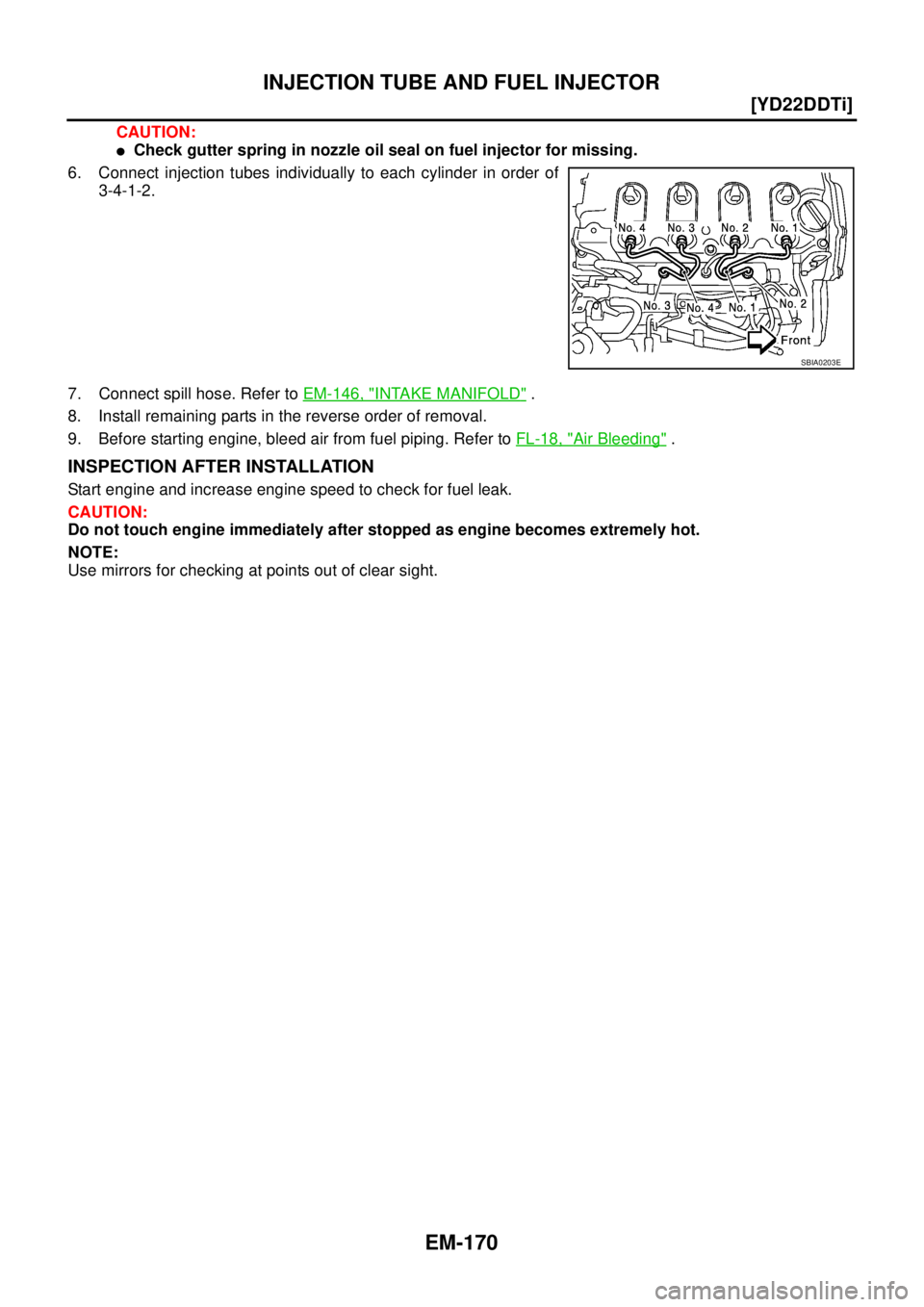
CAUTION:
�Check gutter spring in nozzle oil seal on fuel injector for missing.
6. Connect injection tubes individually to each cylinder in order of
3-4-1-2.
7. Connect spill hose. Refer to EM-146, "
INTAKE MANIFOLD" .
8. Install remaining parts in the reverse order of removal.
9. Before starting engine, bleed air from fuel piping. Refer to FL-18, "
Air Bleeding" .
INSPECTION AFTER INSTALLATION
Start engine and increase engine speed to check for fuel leak.
CAUTION:
Do not touch engine immediately after stopped as engine becomes extremely hot.
NOTE:
Use mirrors for checking at points out of clear sight.
SBIA0203E
Page 226 of 4555
![NISSAN X-TRAIL 2005 Service Repair Manual EM-172
[YD22DDTi]
FUEL PUMP
6. Remove RH engine undercover.
7. Remove front exhaust tube. Refer to EX-2, "
EXHAUST SYSTEM" .
8. Remove fuel hoses from fuel pump.
CAUTION:
�While hoses are disconnect](/manual-img/5/57403/w960_57403-225.png "NISSAN X-TRAIL 2005 Service Repair Manual EM-172
[YD22DDTi]
FUEL PUMP
6. Remove RH engine undercover.
7. Remove front exhaust tube. Refer to EX-2, \"
EXHAUST SYSTEM\" .
8. Remove fuel hoses from fuel pump.
CAUTION:
�While hoses are disconnect")
EM-172
[YD22DDTi]
FUEL PUMP
6. Remove RH engine undercover.
7. Remove front exhaust tube. Refer to EX-2, "
EXHAUST SYSTEM" .
8. Remove fuel hoses from fuel pump.
CAUTION:
�While hoses are disconnected, plug them to prevent fuel from draining.
�Be careful not to spill fuel in the engine component.
9. Disconnect harness connector from fuel pump.
10. Remove injection tube center, clip and insert rubber. Refer to EM-167, "
INJECTION TUBE AND FUEL
INJECTOR" .
CAUTION:
Be careful not to spill fuel in the engine component.
11. Remove secondary timing chain. Refer to EM-193, "
Removal and Installation" .
12. Hold fuel pump sprocket and remove bolt.
a. Insert the positioning stopper pin (special service tool) into the
hole 6 mm (0.24 in) in the diameter on the fuel pump sprocket.
b. Using the TORX wrench (special service tool), turn pump shaft
little by little to adjust the position of fuel pump sprocket so that
the holes align.
c. Push the positioning stopper pin (special service tool) through
fuel pump sprocket to fuel pump body to hold fuel pump
sprocket.
�Insert the positioning stopper pin until its flange contacts the fuel
pump sprocket.
13. Using the hexagon wrench (special service tool) remove tighten-
ing bolts of fuel pump sprocket.
MBIA0049E
PBIC2535E
PBIC2404E
Page 231 of 4555
![NISSAN X-TRAIL 2005 Service Repair Manual FUEL PUMP
EM-177
[YD22DDTi]
C
D
E
F
G
H
I
J
K
L
MA
EM
11. Using the hexagon wrench (special service tool), tighten the
sprocket tightening bolt.
�When the washer of the fuel pump sprocket is removed](/manual-img/5/57403/w960_57403-230.png "NISSAN X-TRAIL 2005 Service Repair Manual FUEL PUMP
EM-177
[YD22DDTi]
C
D
E
F
G
H
I
J
K
L
MA
EM
11. Using the hexagon wrench (special service tool), tighten the
sprocket tightening bolt.
�When the washer of the fuel pump sprocket is removed")
FUEL PUMP
EM-177
[YD22DDTi]
C
D
E
F
G
H
I
J
K
L
MA
EM
11. Using the hexagon wrench (special service tool), tighten the
sprocket tightening bolt.
�When the washer of the fuel pump sprocket is removed,
install it with the marking “F” (front) facing the front of the
engine.
12. Pull out the positioning stopper pin (special service tool).
13. Install secondary timing chain. Refer to EM-193, "
Removal and Installation" .
14. Install injection tube center as follows: Refer to EM-167, "
INJECTION TUBE AND FUEL INJECTOR" .
a. Pre-set clip and insert rubber to injection tube center.
b. Pre-tight nut of injection tube center to fuel pump and fuel rail by hand. (until seal surface touched)
c. Adjust clip dimension and tight bolt for clip to intake manifold by tool.
d. Tight nut of injection tube center to fuel pump by tool.
e. Tight nut of injection tube center to fuel rail by tool.
15. Connect the harness connector to fuel pump.
16. Install fuel hoses.
17. Hereafter, install in the reverse order of removal.
18. Before starting engine, bleed air from fuel piping. Refer to FL-18, "
Air Bleeding" .
PBIC2404E
Page 232 of 4555
EM-178
[YD22DDTi]
ROCKER COVER
ROCKER COVERPFP:13264
Removal and InstallationEBS00LRQ
REMOVAL
1. Remove charge air cooler. Refer to EM-144, "Removal and Installation" .
2. Disconnect harness connector from fuel injector. Refer to EM-167, "
INJECTION TUBE AND FUEL INJEC-
TOR" .
3. Remove injection tube. Refer to EM-167, "
INJECTION TUBE AND FUEL INJECTOR" .
4. Remove injection nozzle oil seal.
�Using the flat-bladed screwdriver, pry flange to remove nozzle
oil seal.
5. Remove rocker cover.
1. Nozzle oil seal 2. Oil filler cap 3. Gasket
4. Rocker cover 5. Washer
PBIC2318E
PBIC0944E
![NISSAN X-TRAIL 2005 Service Repair Manual INJECTION TUBE AND FUEL INJECTOR
EM-167
[YD22DDTi]
C
D
E
F
G
H
I
J
K
L
MA
EM
INJECTION TUBE AND FUEL INJECTORPFP:00018
Removal and InstallationEBS00LRO
REMOVAL
1. Remove charge air cooler. Refer to](/manual-img/5/57403/w960_57403-220.png "NISSAN X-TRAIL 2005 Service Repair Manual INJECTION TUBE AND FUEL INJECTOR
EM-167
[YD22DDTi]
C
D
E
F
G
H
I
J
K
L
MA
EM
INJECTION TUBE AND FUEL INJECTORPFP:00018
Removal and InstallationEBS00LRO
REMOVAL
1. Remove charge air cooler. Refer to")
![NISSAN X-TRAIL 2005 Service Repair Manual EM-168
[YD22DDTi]
INJECTION TUBE AND FUEL INJECTOR
b. Remove injection tubes in order of 2-1-4-3 individually.
CAUTION:
Be careful not to allow leaked fuel to contaminate engine
room. Especially, en](/manual-img/5/57403/w960_57403-221.png "NISSAN X-TRAIL 2005 Service Repair Manual EM-168
[YD22DDTi]
INJECTION TUBE AND FUEL INJECTOR
b. Remove injection tubes in order of 2-1-4-3 individually.
CAUTION:
Be careful not to allow leaked fuel to contaminate engine
room. Especially, en")
![NISSAN X-TRAIL 2005 Service Repair Manual EM-178
[YD22DDTi]
ROCKER COVER
ROCKER COVERPFP:13264
Removal and InstallationEBS00LRQ
REMOVAL
1. Remove charge air cooler. Refer to EM-144, "Removal and Installation" .
2. Disconnect harness connect](/manual-img/5/57403/w960_57403-231.png "NISSAN X-TRAIL 2005 Service Repair Manual EM-178
[YD22DDTi]
ROCKER COVER
ROCKER COVERPFP:13264
Removal and InstallationEBS00LRQ
REMOVAL
1. Remove charge air cooler. Refer to EM-144, \"Removal and Installation\" .
2. Disconnect harness connect")