Page 264 of 4555
![NISSAN X-TRAIL 2005 Service Repair Manual EM-210
[YD22DDTi]
CYLINDER HEAD
10. Complete this operation as follows:
a. Turn the ignition switch to “OFF”.
b. Disconnect the battery cable from the negative terminal.
c. Install glow plug a](/manual-img/5/57403/w960_57403-263.png "NISSAN X-TRAIL 2005 Service Repair Manual EM-210
[YD22DDTi]
CYLINDER HEAD
10. Complete this operation as follows:
a. Turn the ignition switch to “OFF”.
b. Disconnect the battery cable from the negative terminal.
c. Install glow plug a")
EM-210
[YD22DDTi]
CYLINDER HEAD
10. Complete this operation as follows:
a. Turn the ignition switch to “OFF”.
b. Disconnect the battery cable from the negative terminal.
c. Install glow plug and install all the parts removed in step 4.
d. Install fuel pump fuse [ENG CONT (20A)].
e. Connect the battery cable to the negative terminal.
f. Using CONSULT-II make sure no DTC is indicated for items of self-diagnosis.
Removal and InstallationEBS00LRW
REMOVAL
1. Drain engine coolant. Refer to CO-32, "Changing Engine Coolant" .
2. Remove the following:
�Charge air cooler (Refer to EM-144, "Removal and Installation" .)
�Rocker cover (Refer to EM-178, "Removal and Installation" .)
�Air cleaner and air duct (Refer to EM-142, "Removal and Installation" .)
�Vacuum pump (Refer to EM-163, "Removal and Installation" .)
�Spill tube and fuel injector (Refer to EM-167, "Removal and Installation" .)
�Intake manifold (Refer to EM-146, "Removal and Installation" .)
�Exhaust manifold and turbocharger (Refer to EM-151, "Removal and Installation" .)
�Secondary timing chain (Refer to EM-193, "Removal and Installation" .)
�Camshaft (Refer to EM-180, "Removal and Installation" .)
3. Remove cylinder head assembly.
1. Glow plug 2. Cylinder head assembly 3. Cylinder head bolt
4. Copper washer 5. Engine coolant temperature sensor 6. Gasket
7. Water outlet 8. Dowel pin 9. Cylinder gasket
10. Glow harness 11. Glow plate 12. Cap
PBIC2437E
Page 628 of 4555
![NISSAN X-TRAIL 2005 Service Repair Manual EC-224
[QR (WITH EURO-OBD)]
DTC P0171 FUEL INJECTION SYSTEM FUNCTION
6. CHECK FUNCTION OF INJECTORS
With CONSULT-II
1. Start engine.
2. Perform “POWER BALANCE” in “ACTIVE TEST” mode with
CO](/manual-img/5/57403/w960_57403-627.png "NISSAN X-TRAIL 2005 Service Repair Manual EC-224
[QR (WITH EURO-OBD)]
DTC P0171 FUEL INJECTION SYSTEM FUNCTION
6. CHECK FUNCTION OF INJECTORS
With CONSULT-II
1. Start engine.
2. Perform “POWER BALANCE” in “ACTIVE TEST” mode with
CO")
EC-224
[QR (WITH EURO-OBD)]
DTC P0171 FUEL INJECTION SYSTEM FUNCTION
6. CHECK FUNCTION OF INJECTORS
With CONSULT-II
1. Start engine.
2. Perform “POWER BALANCE” in “ACTIVE TEST” mode with
CONSULT-II.
3. Make sure that each circuit produces a momentary engine
speed drop.
Without CONSULT-II
1. Start engine.
2. Listen to each injector operating sound.
OK or NG
OK >> GO TO 7.
NG >> Perform trouble diagnosis for EC-451, "
INJECTOR CIR-
CUIT" .
7. CHECK INJECTOR
1. Confirm that the engine is cooled down and there are no fire hazards near the vehicle.
2. Turn ignition switch OFF.
3. Remove injector gallery assembly. Refer to EM-34, "
FUEL INJECTOR AND FUEL TUBE" .
Keep fuel hose and all injectors connected to injector gallery.
The injector harness connectors should remain connected.
4. Disconnect all ignition coil harness connectors.
5. Prepare pans or saucers under each injector.
6. Crank engine for about 3 seconds. Make sure that fuel sprays
out from injectors.
OK or NG
OK >> GO TO 8.
NG >> Replace injectors from which fuel does not spray out.
Always replace O-ring with new ones.
8. CHECK INTERMITTENT INCIDENT
Refer to EC-124, "
TROUBLE DIAGNOSIS FOR INTERMITTENT INCIDENT" .
>>INSPECTION END
PBIB0133E
Clicking noise should be heard.
PBIB1986E
Fuel should be sprayed evenly for each injector.
PBIB1726E
Page 634 of 4555
EC-230
[QR (WITH EURO-OBD)]
DTC P0172 FUEL INJECTION SYSTEM FUNCTION
7. CHECK INJECTOR
1. Remove injector assembly. Refer to EM-34, "
FUEL INJECTOR AND FUEL TUBE" .
Keep fuel hose and all injectors connected to injector gallery.
2. Confirm that the engine is cooled down and there are no fire hazards near the vehicle.
3. Disconnect injector harness connectors.
4. Disconnect all ignition coil harness connectors.
5. Prepare pans or saucers under each injectors.
6. Crank engine for about 3 seconds.
Make sure fuel does not drip from injector.
OK or NG
OK (Does not drip.)>>GO TO 8.
NG (Drips.)>>Replace the injectors from which fuel is dripping. Always replace O-ring with new one.
8. CHECK INTERMITTENT INCIDENT
Refer to EC-124, "
TROUBLE DIAGNOSIS FOR INTERMITTENT INCIDENT" .
>>INSPECTION END
Page 668 of 4555
![NISSAN X-TRAIL 2005 Service Repair Manual EC-264
[QR (WITH EURO-OBD)]
DTC P0420 THREE WAY CATALYST FUNCTION
DTC P0420 THREE WAY CATALYST FUNCTIONPFP:20905
On Board Diagnosis LogicEBS010Q8
The ECM monitors the switching frequency ratio of he](/manual-img/5/57403/w960_57403-667.png "NISSAN X-TRAIL 2005 Service Repair Manual EC-264
[QR (WITH EURO-OBD)]
DTC P0420 THREE WAY CATALYST FUNCTION
DTC P0420 THREE WAY CATALYST FUNCTIONPFP:20905
On Board Diagnosis LogicEBS010Q8
The ECM monitors the switching frequency ratio of he")
EC-264
[QR (WITH EURO-OBD)]
DTC P0420 THREE WAY CATALYST FUNCTION
DTC P0420 THREE WAY CATALYST FUNCTIONPFP:20905
On Board Diagnosis LogicEBS010Q8
The ECM monitors the switching frequency ratio of heated oxygen
sensors 1 and 2.
A three way catalyst (manifold) with high oxygen storage capacity
will indicate a low switching frequency of heated oxygen sensor 2.
As oxygen storage capacity decreases, the heated oxygen sensor 2
switching frequency will increase.
When the frequency ratio of heated oxygen sensors 1 and 2
approaches a specified limit value, the three way catalyst (manifold)
malfunction is diagnosed.
DTC Confirmation ProcedureEBS010Q9
NOTE:
If DTC Confirmation Procedure has been previously conducted, always turn ignition switch OFF and wait at
least 10 seconds before conducting the next test.
WITH CONSULT-II
TESTING CONDITION:
�Open engine hood before conducting the following procedure.
�Do not hold engine speed for more than the specified minutes below.
1. Start Engine and warm it up to the normal operating temperature.
2. Turn ignition switch OFF and wait at least 10 seconds.
3. Start engine and keep the engine speed between 3,500 and 4,00 rpm for at least 1 minute under no load.
4. Let engine idle for 1 minute.
5. Select “DTC & SRT CONFIRMATION” then “SRT WORK SUP-
PORT” mode with CONSULT-II.
6. Start engine.
7. Rev engine up to 2,000 to 3,000 rpm and hold it for 3 consecu-
tive minutes then release the accelerator pedal completely.
If “INCMP” of “CATALYST” changed to “COMPLT”, go to step 10
8. Wait 5 seconds at idle.
SEF484YF
DTC No. Trouble diagnosis name DTC detecting condition Possible cause
P0420
0420Catalyst system efficiency
below threshold
�Three way catalyst (manifold) does not operate
properly.
�Three way catalyst (manifold) does not have
enough oxygen storage capacity.
�Three way catalyst (manifold)
�Exhaust tube
�Intake air leaks
�Fuel injector
�Fuel injector leaks
�Spark plug
�Improper ignition timing
PBIB0566E
Page 671 of 4555
![NISSAN X-TRAIL 2005 Service Repair Manual DTC P0420 THREE WAY CATALYST FUNCTION
EC-267
[QR (WITH EURO-OBD)]
C
D
E
F
G
H
I
J
K
L
MA
EC
OK or NG
OK >> GO TO 5.
NG >> Follow the EC-79, "
Basic Inspection" .
5. CHECK INJECTORS
1. Refer to Wirin](/manual-img/5/57403/w960_57403-670.png "NISSAN X-TRAIL 2005 Service Repair Manual DTC P0420 THREE WAY CATALYST FUNCTION
EC-267
[QR (WITH EURO-OBD)]
C
D
E
F
G
H
I
J
K
L
MA
EC
OK or NG
OK >> GO TO 5.
NG >> Follow the EC-79, \"
Basic Inspection\" .
5. CHECK INJECTORS
1. Refer to Wirin")
DTC P0420 THREE WAY CATALYST FUNCTION
EC-267
[QR (WITH EURO-OBD)]
C
D
E
F
G
H
I
J
K
L
MA
EC
OK or NG
OK >> GO TO 5.
NG >> Follow the EC-79, "
Basic Inspection" .
5. CHECK INJECTORS
1. Refer to Wiring Diagram for Injectors, EC-452
.
2. Stop engine and then turn ignition switch ON.
3. Check voltage between ECM terminals 22, 23, 41, 42 and
ground with CONSULT-II or tester.
OK or NG
OK >> GO TO 6.
NG >> Perform EC-453, "
Diagnostic Procedure" .
6. CHECK IGNITION SPARK
1. Turn ignition switch OFF.
2. Disconnect all injector harness connectors.
3. Disconnect ignition coil assembly from rocker cover.
4. Disconnect spark plug from ignition coil assembly.
5. Connect a known-good spark plug to the ignition coil assembly.
6. Place end of spark plug against a suitable ground and crank engine.
7. Check for spark.
OK or NG
OK >> GO TO 7.
NG >> Check ignition coil with power transistor and their circuit.
Refer to EC-440, "
IGNITION SIGNAL" .
7. CHECK INJECTOR
1. Turn ignition switch OFF.
2. Remove injector assembly.
Refer to EM-34, "
FUEL INJECTOR AND FUEL TUBE" .
Keep fuel hose and all injectors connected to injector gallery.
3. Disconnect all ignition coil harness connectors.
4. Reconnect all injector harness connectors disconnected.
5. Turn ignition switch ON.
Make sure fuel does not drip from injector.
OK or NG
OK (Does not drip.)>>GO TO 8.
NG (Drips.)>>Replace the injector(s) from which fuel is dripping.Voltage: Battery voltage
MBIB0030E
SEF575Q
Page 726 of 4555
![NISSAN X-TRAIL 2005 Service Repair Manual EC-322
[QR (WITH EURO-OBD)]
DTC P1143 HO2S1
DTC P1143 HO2S1PFP:22690
Component DescriptionEBS010S3
The heated oxygen sensor 1 is placed into the exhaust manifold. It
detects the amount of oxygen in](/manual-img/5/57403/w960_57403-725.png "NISSAN X-TRAIL 2005 Service Repair Manual EC-322
[QR (WITH EURO-OBD)]
DTC P1143 HO2S1
DTC P1143 HO2S1PFP:22690
Component DescriptionEBS010S3
The heated oxygen sensor 1 is placed into the exhaust manifold. It
detects the amount of oxygen in")
EC-322
[QR (WITH EURO-OBD)]
DTC P1143 HO2S1
DTC P1143 HO2S1PFP:22690
Component DescriptionEBS010S3
The heated oxygen sensor 1 is placed into the exhaust manifold. It
detects the amount of oxygen in the exhaust gas compared to the
outside air. The heated oxygen sensor 1 has a closed-end tube
made of ceramic zirconia. The zirconia generates voltage from
approximately 1V in richer conditions to 0V in leaner conditions. The
heated oxygen sensor 1 signal is sent to the ECM. The ECM adjusts
the injection pulse duration to achieve the ideal air-fuel ratio. The
ideal air-fuel ratio occurs near the radical change from 1V to 0V.
CONSULT-II Reference Value in Data Monitor ModeEBS010S4
Specification data are reference values.
On Board Diagnosis LogicEBS010S5
To judge the malfunction, the output from the heated oxygen sensor
1 is monitored to determine whether the “rich” output is sufficiently
high and whether the “lean” output is sufficiently low. When both the
outputs are shifting to the lean side, the malfunction will be detected.
SEF463R
SEF288D
MONITOR ITEM CONDITION SPECIFICATION
HO2S1 (B1)
�Engine: After warming upMaintaining engine speed at 2,000
rpm0 - 0.3V ←→ Approx. 0.6 - 1.0V
HO2S1 MNTR (B1)LEAN ←→ RICH
Changes more than 5 times dur-
ing 10 seconds.
SEF300U
DTC No. Trouble diagnosis name DTC detecting condition Possible cause
P1143
1143Heated oxygen sensor 1
lean shift monitoringThe maximum and minimum voltage from the
sensor are not reached to the specified voltages.
�Heated oxygen sensor 1
�Heated oxygen sensor 1 heater
�Fuel pressure
�Fuel injector
�Intake air leaks
Page 732 of 4555
![NISSAN X-TRAIL 2005 Service Repair Manual EC-328
[QR (WITH EURO-OBD)]
DTC P1144 HO2S1
DTC P1144 HO2S1PFP:22690
Component DescriptionEBS010SB
The heated oxygen sensor 1 is placed into the exhaust manifold. It
detects the amount of oxygen in](/manual-img/5/57403/w960_57403-731.png "NISSAN X-TRAIL 2005 Service Repair Manual EC-328
[QR (WITH EURO-OBD)]
DTC P1144 HO2S1
DTC P1144 HO2S1PFP:22690
Component DescriptionEBS010SB
The heated oxygen sensor 1 is placed into the exhaust manifold. It
detects the amount of oxygen in")
EC-328
[QR (WITH EURO-OBD)]
DTC P1144 HO2S1
DTC P1144 HO2S1PFP:22690
Component DescriptionEBS010SB
The heated oxygen sensor 1 is placed into the exhaust manifold. It
detects the amount of oxygen in the exhaust gas compared to the
outside air. The heated oxygen sensor 1 has a closed-end tube
made of ceramic zirconia. The zirconia generates voltage from
approximately 1V in richer conditions to 0V in leaner conditions. The
heated oxygen sensor 1 signal is sent to the ECM. The ECM adjusts
the injection pulse duration to achieve the ideal air-fuel ratio. The
ideal air-fuel ratio occurs near the radical change from 1V to 0V.
CONSULT-II Reference Value in Data Monitor ModeEBS010SC
Specification data are reference values.
On Board Diagnosis LogicEBS010SD
To judge the malfunction, the output from the heated oxygen sensor
1 is monitored to determine whether the “rich” output is sufficiently
high and “lean” output is sufficiently low. When both the outputs are
shifting to the rich side, the malfunction will be detected.
SEF463R
SEF288D
MONITOR ITEM CONDITION SPECIFICATION
HO2S1 (B1)
�Engine: After warming upMaintaining engine speed at 2,000
rpm0 - 0.3V ←→ Approx. 0.6 - 1.0V
HO2S1 MNTR (B1)LEAN ←→ RICH
Changes more than 5 times dur-
ing 10 seconds.
SEF299U
DTC No. Trouble diagnosis name DTC detecting condition Possible cause
P1144
1144Heated oxygen sensor 1
rich shift monitoringThe maximum and minimum voltages from the
sensor are beyond the specified voltages.
�Heated oxygen sensor 1
�Heated oxygen sensor 1 heater
�Fuel pressure
�Fuel injector
Page 860 of 4555
EC-456
[QR (WITH EURO-OBD)]
INJECTOR CIRCUIT
6. DETECT MALFONCTIONING PART
Check the following.
�Harness connectors F101, F1
�Harness for open or short between injector and ECM
>> Repair open circuit or short to ground or short to power in harness or connectors.
7. CHECK INJECTOR
Refer to EC-456, "
Component Inspection" .
OK or NG
OK >> GO TO 8.
NG >> Replace injector.
8. CHECK INTERMITTENT INCIDENT
Refer to EC-124, "
TROUBLE DIAGNOSIS FOR INTERMITTENT INCIDENT" .
>>INSPECTION END
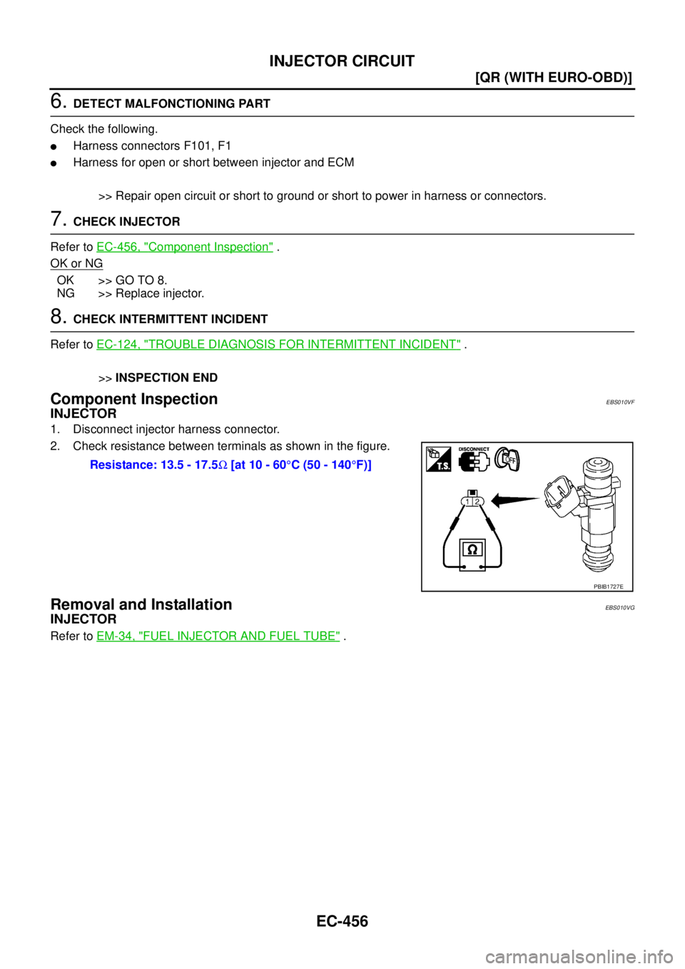
Component InspectionEBS010VF
INJECTOR
1. Disconnect injector harness connector.
2. Check resistance between terminals as shown in the figure.
Removal and InstallationEBS010VG
INJECTOR
Refer to EM-34, "FUEL INJECTOR AND FUEL TUBE" . Resistance: 13.5 - 17.5Ω [at 10 - 60°C (50 - 140°F)]
PBIB1727E
![NISSAN X-TRAIL 2005 Service Repair Manual EC-230
[QR (WITH EURO-OBD)]
DTC P0172 FUEL INJECTION SYSTEM FUNCTION
7. CHECK INJECTOR
1. Remove injector assembly. Refer to EM-34, "
FUEL INJECTOR AND FUEL TUBE" .
Keep fuel hose and all injectors](/manual-img/5/57403/w960_57403-633.png "NISSAN X-TRAIL 2005 Service Repair Manual EC-230
[QR (WITH EURO-OBD)]
DTC P0172 FUEL INJECTION SYSTEM FUNCTION
7. CHECK INJECTOR
1. Remove injector assembly. Refer to EM-34, \"
FUEL INJECTOR AND FUEL TUBE\" .
Keep fuel hose and all injectors")