Page 3877 of 4555

INSTRUMENT PANEL ASSEMBLY
IP-11
C
D
E
F
G
H
J
K
L
MA
B
IP
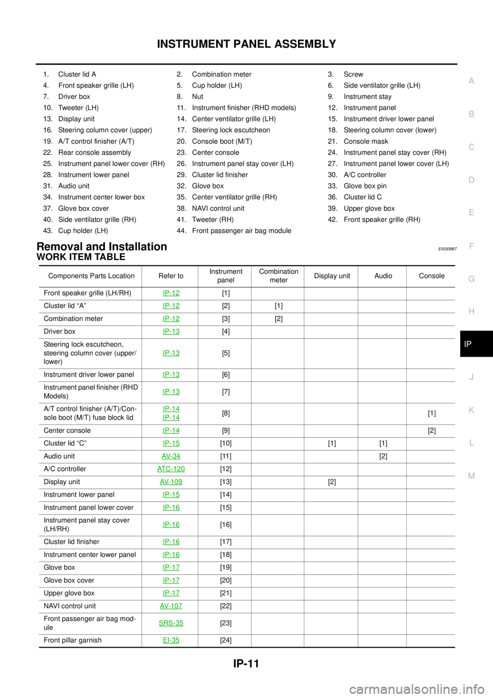
Removal and InstallationEIS008BT
WORK ITEM TABLE
1. Cluster lid A 2. Combination meter 3. Screw
4. Front speaker grille (LH) 5. Cup holder (LH) 6. Side ventilator grille (LH)
7. Driver box 8. Nut 9. Instrument stay
10. Tweeter (LH) 11. Instrument finisher (RHD models) 12. Instrument panel
13. Display unit 14. Center ventilator grille (LH) 15. Instrument driver lower panel
16. Steering column cover (upper) 17. Steering lock escutcheon 18. Steering column cover (lower)
19. A/T control finisher (A/T) 20. Console boot (M/T) 21. Console mask
22. Rear console assembly 23. Center console 24. Instrument panel stay cover (RH)
25. Instrument panel lower cover (RH) 26. Instrument panel stay cover (LH) 27. Instrument panel lower cover (LH)
28. Instrument lower panel 29. Cluster lid finisher 30. A/C controller
31. Audio unit 32. Glove box 33. Glove box pin
34. Instrument center lower box 35. Center ventilator grille (RH) 36. Cluster lid C
37. Glove box cover 38. NAVI control unit 39. Upper glove box
40. Side ventilator grille (RH) 41. Tweeter (RH) 42. Front speaker grille (RH)
43. Cup holder (LH) 44. Front passenger air bag module
Components Parts Location Refer toInstrument
panelCombination
meterDisplay unit Audio Console
Front speaker grille (LH/RH)IP-12
[1]
Cluster lid “A”IP-12
[2] [1]
Combination meterIP-12
[3] [2]
Driver boxIP-13
[4]
Steering lock escutcheon,
steering column cover (upper/
lower)IP-13
[5]
Instrument driver lower panel IP-13
[6]
Instrument panel finisher (RHD
Models)IP-13
[7]
A/T control finisher (A/T)/Con-
sole boot (M/T) fuse block lidIP-14
IP-14[8] [1]
Center consoleIP-14
[9] [2]
Cluster lid “C”IP-15
[10] [1] [1]
Audio unitAV- 3 4
[11] [2]
A/C controllerATC-120
[12]
Display unitAV- 1 0 9
[13] [2]
Instrument lower panelIP-15
[14]
Instrument panel lower cover IP-16
[15]
Instrument panel stay cover
(LH/RH)IP-16
[16]
Cluster lid finisherIP-16
[17]
Instrument center lower panelIP-16
[18]
Glove boxIP-17
[19]
Glove box coverIP-17
[20]
Upper glove boxIP-17
[21]
NAVI control unitAV- 1 0 7
[22]
Front passenger air bag mod-
uleSRS-35
[23]
Front pillar garnishEI-35
[24]
Page 3878 of 4555
IP-12
INSTRUMENT PANEL ASSEMBLY
[ ]: The number shows the removal order.
REMOVAL
Front Speaker Grille (LH/RH)
1. Insert a remover into front speaker grille door side edge, and
then disengage pawls and clips.
2. Pull forward and remove.
Cluster Lid A
Disengage clips by pulling cluster lid A frontward to remove.
CAUTION:
During removal or installation, use shop cloth to protect sur-
rounding area from damage.
Combination Meter
1. Remove screw.
2. Disconnect connector on back and remove combination meter.
CAUTION:
During removal or installation, use shop cloth to protect
surrounding area from damage.
Instrument panelIP-18[25]
Side ventilator grille (LH/RH)ATC-138
[26]
Cup holderIP-18
[27] Components Parts Location Refer toInstrument
panelCombination
meterDisplay unit Audio Console
PIIA9899E
PIIA7393E
PIIA7394JPIIA7394E
Page 3881 of 4555

INSTRUMENT PANEL ASSEMBLY
IP-15
C
D
E
F
G
H
J
K
L
MA
B
IP
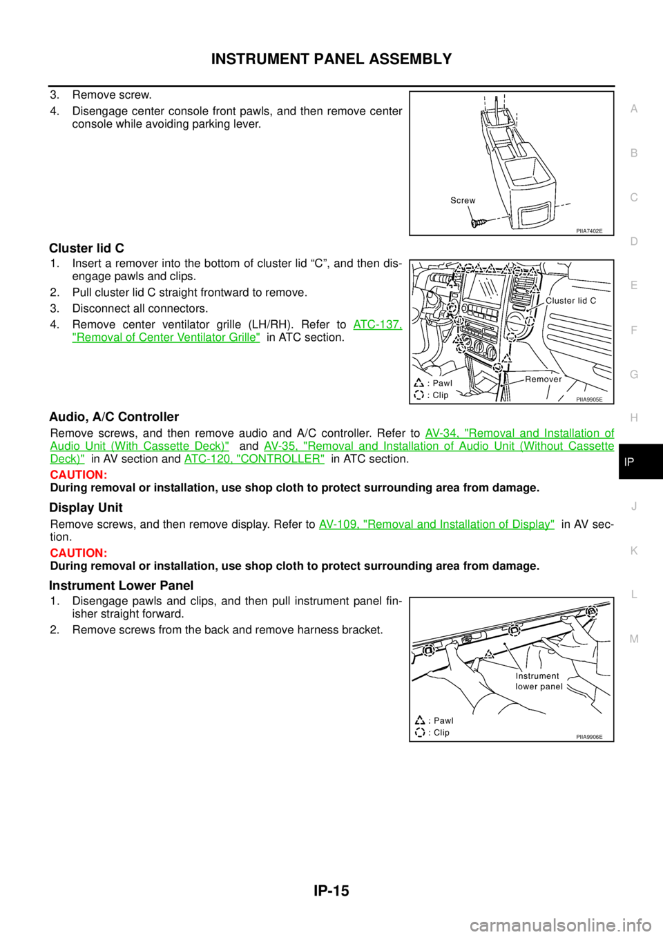
3. Remove screw.
4. Disengage center console front pawls, and then remove center
console while avoiding parking lever.
Cluster lid C
1. Insert a remover into the bottom of cluster lid “C”, and then dis-
engage pawls and clips.
2. Pull cluster lid C straight frontward to remove.
3. Disconnect all connectors.
4. Remove center ventilator grille (LH/RH). Refer to ATC-137,
"Removal of Center Ventilator Grille" in ATC section.
Audio, A/C Controller
Remove screws, and then remove audio and A/C controller. Refer to AV- 3 4 , "Removal and Installation of
Audio Unit (With Cassette Deck)" and AV- 3 5 , "Removal and Installation of Audio Unit (Without Cassette
Deck)" in AV section and ATC-120, "CONTROLLER" in ATC section.
CAUTION:
During removal or installation, use shop cloth to protect surrounding area from damage.
Display Unit
Remove screws, and then remove display. Refer to AV- 1 0 9 , "Removal and Installation of Display" in AV sec-
tion.
CAUTION:
During removal or installation, use shop cloth to protect surrounding area from damage.
Instrument Lower Panel
1. Disengage pawls and clips, and then pull instrument panel fin-
isher straight forward.
2. Remove screws from the back and remove harness bracket.
PIIA7402E
PIIA9905E
PIIA9906E
Page 3882 of 4555
IP-16
INSTRUMENT PANEL ASSEMBLY
Instrument Panel Lower Cover (LH/RH)
Disengage pawls and pull it to rear of vehicle.
Instrument Panel Stay Cover (LH/RH)
1. Remove screws.
2. Disengage pawls and pull it to outside of vehicle.
Cluster Lid Finisher
1. Remove screws.
2. Pull the bottom of cluster lid finisher to the rearward of the vehi-
cle, and remove it so as to avoid interference around upper
screw holes.
Instrument Center Lower Panel
Remove screws, and then pull it forward to remove.
CAUTION:
During removal or installation, use shop cloth to protect sur-
rounding area from damage.
PIIA9907E
PIIA9908E
PIIA7407E
PIIB0334E
Page 3894 of 4555

SE-6
SQUEAK AND RATTLE TROUBLE DIAGNOSES
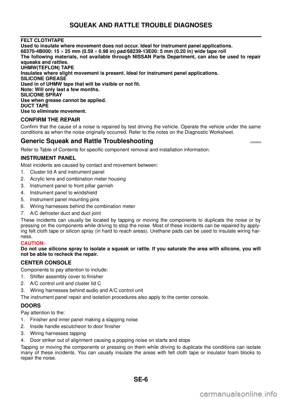
FELT CLOTHTAPE
Used to insulate where movement does not occur. Ideal for instrument panel applications.
68370-4B000: 15 × 25 mm (0.59 × 0.98 in) pad/68239-13E00: 5 mm (0.20 in) wide tape roll
The following materials, not available through NISSAN Parts Department, can also be used to repair
squeaks and rattles.
UHMW(TEFLON) TAPE
Insulates where slight movement is present. Ideal for instrument panel applications.
SILICONE GREASE
Used in of UHMW tape that will be visible or not fit.
Note: Will only last a few months.
SILICONE SPRAY
Use when grease cannot be applied.
DUCT TAPE
Use to eliminate movement.
CONFIRM THE REPAIR
Confirm that the cause of a noise is repaired by test driving the vehicle. Operate the vehicle under the same
conditions as when the noise originally occurred. Refer to the notes on the Diagnostic Worksheet.
Generic Squeak and Rattle TroubleshootingEIS008O2
Refer to Table of Contents for specific component removal and installation information.
INSTRUMENT PANEL
Most incidents are caused by contact and movement between:
1. Cluster lid A and instrument panel
2. Acrylic lens and combination meter housing
3. Instrument panel to front pillar garnish
4. Instrument panel to windshield
5. Instrument panel mounting pins
6. Wiring harnesses behind the combination meter
7. A/C defroster duct and duct joint
These incidents can usually be located by tapping or moving the components to duplicate the noise or by
pressing on the components while driving to stop the noise. Most of these incidents can be repaired by apply-
ing felt cloth tape or silicon spray (in hard to reach areas). Urethane pads can be used to insulate wiring har-
ness.
CAUTION:
Do not use silicone spray to isolate a squeak or rattle. If you saturate the area with silicone, you will
not be able to recheck the repair.
CENTER CONSOLE
Components to pay attention to include:
1. Shifter assembly cover to finisher
2. A/C control unit and cluster lid C
3. Wiring harnesses behind audio and A/C control unit
The instrument panel repair and isolation procedures also apply to the center console.
DOORS
Pay attention to the:
1. Finisher and inner panel making a slapping noise
2. Inside handle escutcheon to door finisher
3. Wiring harnesses tapping
4. Door striker out of alignment causing a popping noise on starts and stops
Tapping or moving the components or pressing on them while driving to duplicate the conditions can isolate
many of these incidents. You can usually insulate the areas with felt cloth tape or insulator foam blocks to
repair the noise.
Page 3957 of 4555
DUCTS AND GRILLES
MTC-33
C
D
E
F
G
H
I
K
L
MA
B
MTC
DUCTS AND GRILLESPFP:27860
Removal and InstallationEJS004HH
REMOVAL
NOTE:
This illustration is for RHD models. The layout for LHD models is symmetrically opposite.
Removal of Center Ventilator Grille
1. Remove cluster lid C. Refer to IP-11, "Removal and Installation" .
2. Remove mounting clips, and then remove center ventilator grille.
1. Side defroster duct (right) 2. Defroster nozzle 3. Side defroster duct (left)
4. Side ventilator duct (left) 5. Front speaker grille (left) 6. Cup holder (left)
7. Side ventilator grille (left) 8. Multi-box (Instrument center lower
panel)9. Side ventilator grille (right)
10. Cup holder (right) 11. Front speaker grille (right) 12. Side ventilator duct (right)
13. Adaptor 14. Center ventilator grille (left) 15. Multi-box duct
16. Center ventilator grille (right) 17. Driver ventilator grille 18. Instrument panel
RJIA2406J
RJIA2407E
Page 4093 of 4555
HAZARD SWITCH
LT-97
C
D
E
F
G
H
I
J
L
MA
B
LT
HAZARD SWITCHPFP:25290
Removal and Installation EKS003BZ
REMOVAL
1. Remove cluster lid C. Refer to IP-10, "INSTRUMENT PANEL
ASSEMBLY" in “INSTRUMENT PANEL (IP)” section.
2. Press the hazard switch fixing pawls and remove it from the
cluster lid C.
INSTALLATION
Installation is the reverse order of removal.
PKIA8617E
Page 4181 of 4555
COMBINATION METERS
DI-33
C
D
E
F
G
H
I
J
L
MA
B
DI
AMBIENT SENSOR CHECK
Ambient Sensor
After disconnecting ambient sensor harness connector, measure
resistance between terminals 2 and 1 at sensor harness side, using
the table below.
If NG, replace ambient sensor.
Removal and Installation for Combination MeterEKS00EHJ
REMOVAL
1. Remove cluster lid A. Refer to IP-10, "INSTRUMENT PANEL
ASSEMBLY" .
2. Remove the screws (4), and pull out combination meter.
3. Disconnect connectors and remove combination meter.
INSTALLATION
Installation is the reverse order of removal.
Temperature [°C (°F)] Resistance [kΩ]
−15 (5) 12.73
−10 (14) 9.92
−5 (23) 7.80
0 (32) 6.19
5 (41) 4.95
10 (50) 3.99
15 (59) 3.24
20 (68) 2.65
25 (77) 2.19
30 (86) 1.81
35 (95) 1.51
40 (104) 1.27
45 (113) 1.07
RJIA0684E
SKIA8927E