Page 2941 of 4555
FRONT DRIVE SHAFT
FAX-17
C
E
F
G
H
I
J
K
L
MA
B
FA X
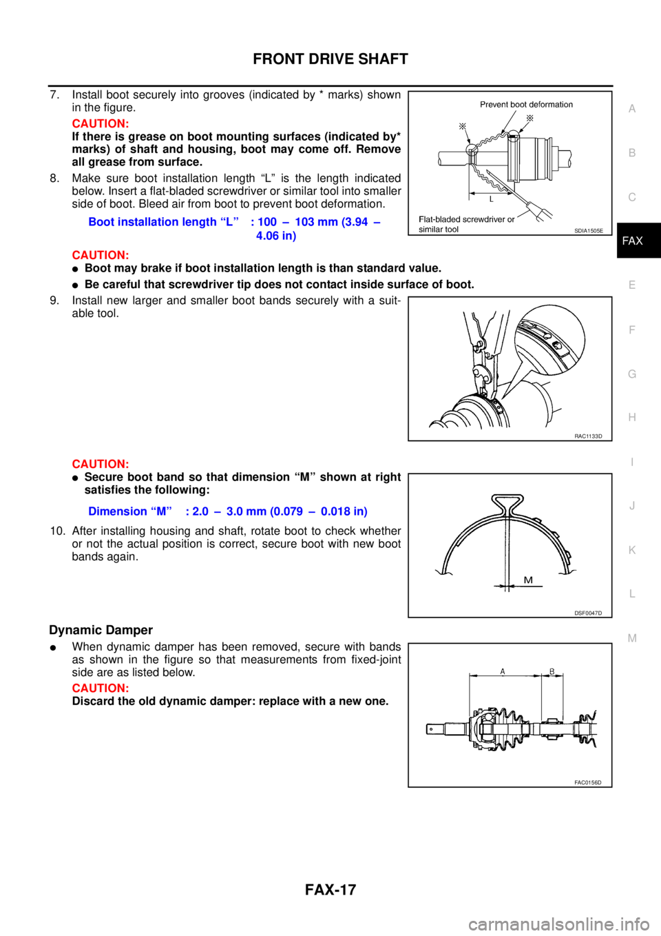
7. Install boot securely into grooves (indicated by * marks) shown
in the figure.
CAUTION:
If there is grease on boot mounting surfaces (indicated by*
marks) of shaft and housing, boot may come off. Remove
all grease from surface.
8. Make sure boot installation length “L” is the length indicated
below. Insert a flat-bladed screwdriver or similar tool into smaller
side of boot. Bleed air from boot to prevent boot deformation.
CAUTION:
�Boot may brake if boot installation length is than standard value.
�Be careful that screwdriver tip does not contact inside surface of boot.
9. Install new larger and smaller boot bands securely with a suit-
able tool.
CAUTION:
�Secure boot band so that dimension “M” shown at right
satisfies the following:
10. After installing housing and shaft, rotate boot to check whether
or not the actual position is correct, secure boot with new boot
bands again.
Dynamic Damper
�When dynamic damper has been removed, secure with bands
as shown in the figure so that measurements from fixed-joint
side are as listed below.
CAUTION:
Discard the old dynamic damper: replace with a new one.Boot installation length “L” : 100 – 103 mm (3.94 –
4.06 in)
SDIA1505E
RAC1133D
Dimension “M” : 2.0 – 3.0 mm (0.079 – 0.018 in)
DSF0047D
FAC0156D
Page 2943 of 4555
SERVICE DATA AND SPECIFICATIONS (SDS)
FAX-19
C
E
F
G
H
I
J
K
L
MA
B
FA X
SERVICE DATA AND SPECIFICATIONS (SDS)PFP:00030
Wheel BearingEDS000IG
Drive ShaftEDS000IH
ZF100SS86, ZF100SS86F, ZF100SS86F+B
Dynamic DamperEDS000II
Axial end play 0.05 mm (0.0020 in)
Rotating torque 1.645 N·m (0.17 kg-m, 15 in-lb) or less
Spring balance reading 10.6 N (1.1 kg, 2.4 lb) or less
Installation location of spring scale
SDIA0148E
Joint type Wheel side Transaxle side
Grease amount 115 - 125 g (4.01 - 4.41 oz) 132 - 142 g (4.69 - 5.04 oz)
Boot length 100 - 103 mm (3.94 - 4.06 in) 84 - 86 mm (3.31 - 3.39 in)
Drive shaft model Applied model Specification Dimension A Dimension B
ZF100SS86 ALL Left 205 - 215 mm (8.07 - 8.46 in) 70 mm (2.76 in)
ZF100SS86F+ BRHD: QR25DE A/T models
QR25DE: M/T models
Right 267 - 273 mm (10.51 - 10.75 in)70 mm (2.76 in)
QR20DE/YD22DDTi M/T models 50 mm (1.97 in)
FAC0156D
Page 2958 of 4555
RAX-14
REAR DRIVE SHAFT
REAR DRIVE SHAFTPFP:39600
Removal and InstallationEDS000FL
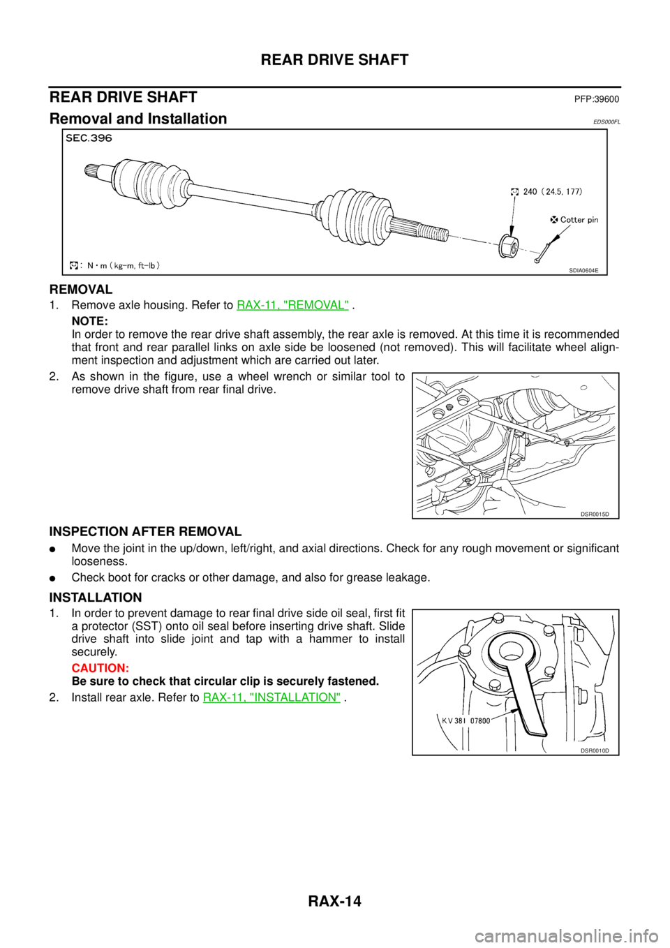
REMOVAL
1. Remove axle housing. Refer to RAX-11, "REMOVAL" .
NOTE:
In order to remove the rear drive shaft assembly, the rear axle is removed. At this time it is recommended
that front and rear parallel links on axle side be loosened (not removed). This will facilitate wheel align-
ment inspection and adjustment which are carried out later.
2. As shown in the figure, use a wheel wrench or similar tool to
remove drive shaft from rear final drive.
INSPECTION AFTER REMOVAL
�Move the joint in the up/down, left/right, and axial directions. Check for any rough movement or significant
looseness.
�Check boot for cracks or other damage, and also for grease leakage.
INSTALLATION
1. In order to prevent damage to rear final drive side oil seal, first fit
a protector (SST) onto oil seal before inserting drive shaft. Slide
drive shaft into slide joint and tap with a hammer to install
securely.
CAUTION:
Be sure to check that circular clip is securely fastened.
2. Install rear axle. Refer to RAX-11, "
INSTALLATION" .
SDIA0604E
DSR0015D
DSR0010D
Page 2959 of 4555
REAR DRIVE SHAFT
RAX-15
C
E
F
G
H
I
J
K
L
MA
B
RAX
Disassembly and AssemblyEDS000FM
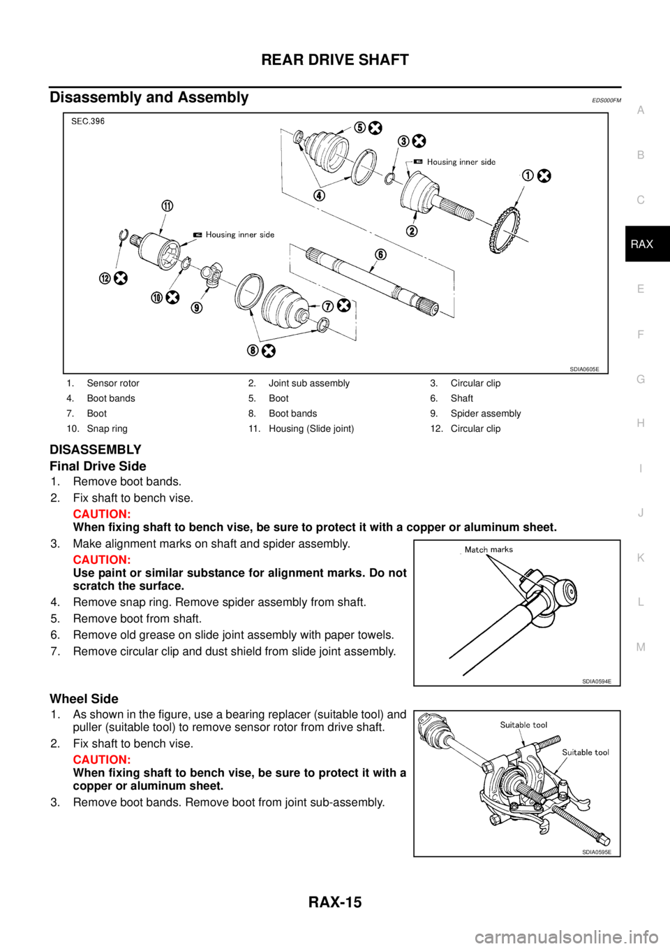
DISASSEMBLY
Final Drive Side
1. Remove boot bands.
2. Fix shaft to bench vise.
CAUTION:
When fixing shaft to bench vise, be sure to protect it with a copper or aluminum sheet.
3. Make alignment marks on shaft and spider assembly.
CAUTION:
Use paint or similar substance for alignment marks. Do not
scratch the surface.
4. Remove snap ring. Remove spider assembly from shaft.
5. Remove boot from shaft.
6. Remove old grease on slide joint assembly with paper towels.
7. Remove circular clip and dust shield from slide joint assembly.
Wheel Side
1. As shown in the figure, use a bearing replacer (suitable tool) and
puller (suitable tool) to remove sensor rotor from drive shaft.
2. Fix shaft to bench vise.
CAUTION:
When fixing shaft to bench vise, be sure to protect it with a
copper or aluminum sheet.
3. Remove boot bands. Remove boot from joint sub-assembly.
1. Sensor rotor 2. Joint sub assembly 3. Circular clip
4. Boot bands 5. Boot 6. Shaft
7. Boot 8. Boot bands 9. Spider assembly
10. Snap ring 11. Housing (Slide joint) 12. Circular clip
SDIA0605E
SDIA0594E
SDIA0595E
Page 2960 of 4555
RAX-16
REAR DRIVE SHAFT
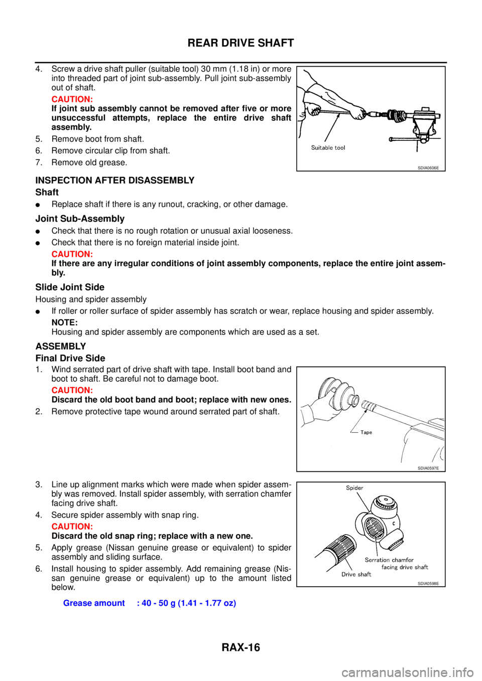
4. Screw a drive shaft puller (suitable tool) 30 mm (1.18 in) or more
into threaded part of joint sub-assembly. Pull joint sub-assembly
out of shaft.
CAUTION:
If joint sub assembly cannot be removed after five or more
unsuccessful attempts, replace the entire drive shaft
assembly.
5. Remove boot from shaft.
6. Remove circular clip from shaft.
7. Remove old grease.
INSPECTION AFTER DISASSEMBLY
Shaft
�Replace shaft if there is any runout, cracking, or other damage.
Joint Sub-Assembly
�Check that there is no rough rotation or unusual axial looseness.
�Check that there is no foreign material inside joint.
CAUTION:
If there are any irregular conditions of joint assembly components, replace the entire joint assem-
bly.
Slide Joint Side
Housing and spider assembly
�If roller or roller surface of spider assembly has scratch or wear, replace housing and spider assembly.
NOTE:
Housing and spider assembly are components which are used as a set.
ASSEMBLY
Final Drive Side
1. Wind serrated part of drive shaft with tape. Install boot band and
boot to shaft. Be careful not to damage boot.
CAUTION:
Discard the old boot band and boot; replace with new ones.
2. Remove protective tape wound around serrated part of shaft.
3. Line up alignment marks which were made when spider assem-
bly was removed. Install spider assembly, with serration chamfer
facing drive shaft.
4. Secure spider assembly with snap ring.
CAUTION:
Discard the old snap ring; replace with a new one.
5. Apply grease (Nissan genuine grease or equivalent) to spider
assembly and sliding surface.
6. Install housing to spider assembly. Add remaining grease (Nis-
san genuine grease or equivalent) up to the amount listed
below.
SDIA0606E
SDIA0597E
Grease amount : 40 - 50 g (1.41 - 1.77 oz)
SDIA0598E
Page 2961 of 4555
REAR DRIVE SHAFT
RAX-17
C
E
F
G
H
I
J
K
L
MA
B
RAX
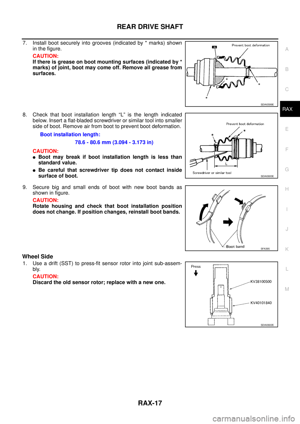
7. Install boot securely into grooves (indicated by * marks) shown
in the figure.
CAUTION:
If there is grease on boot mounting surfaces (indicated by *
marks) of joint, boot may come off. Remove all grease from
surfaces.
8. Check that boot installation length “L” is the length indicated
below. Insert a flat-bladed screwdriver or similar tool into smaller
side of boot. Remove air from boot to prevent boot deformation.
CAUTION:
�Boot may break if boot installation length is less than
standard value.
�Be careful that screwdriver tip does not contact inside
surface of boot.
9. Secure big and small ends of boot with new boot bands as
shown in figure.
CAUTION:
Rotate housing and check that boot installation position
does not change. If position changes, reinstall boot bands.
Wheel Side
1. Use a drift (SST) to press-fit sensor rotor into joint sub-assem-
bly.
CAUTION:
Discard the old sensor rotor; replace with a new one.
SDIA0599E
Boot installation length:
78.6 - 80.6 mm (3.094 - 3.173 in)
SDIA0600E
SFA395
SDIA0602E
Page 2962 of 4555
RAX-18
REAR DRIVE SHAFT
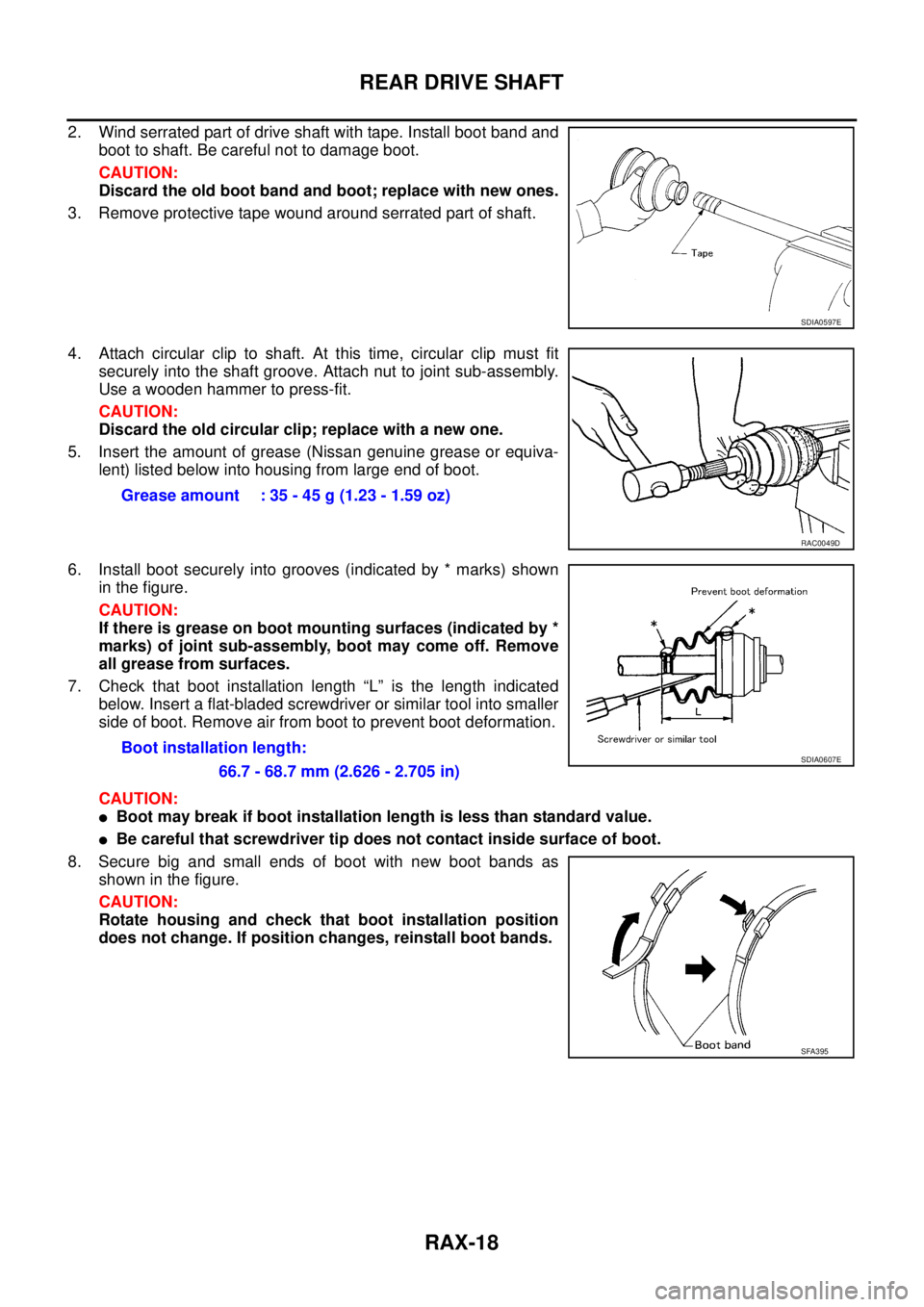
2. Wind serrated part of drive shaft with tape. Install boot band and
boot to shaft. Be careful not to damage boot.
CAUTION:
Discard the old boot band and boot; replace with new ones.
3. Remove protective tape wound around serrated part of shaft.
4. Attach circular clip to shaft. At this time, circular clip must fit
securely into the shaft groove. Attach nut to joint sub-assembly.
Use a wooden hammer to press-fit.
CAUTION:
Discard the old circular clip; replace with a new one.
5. Insert the amount of grease (Nissan genuine grease or equiva-
lent) listed below into housing from large end of boot.
6. Install boot securely into grooves (indicated by * marks) shown
in the figure.
CAUTION:
If there is grease on boot mounting surfaces (indicated by *
marks) of joint sub-assembly, boot may come off. Remove
all grease from surfaces.
7. Check that boot installation length “L” is the length indicated
below. Insert a flat-bladed screwdriver or similar tool into smaller
side of boot. Remove air from boot to prevent boot deformation.
CAUTION:
�Boot may break if boot installation length is less than standard value.
�Be careful that screwdriver tip does not contact inside surface of boot.
8. Secure big and small ends of boot with new boot bands as
shown in the figure.
CAUTION:
Rotate housing and check that boot installation position
does not change. If position changes, reinstall boot bands.
SDIA0597E
Grease amount : 35 - 45 g (1.23 - 1.59 oz)
RAC0049D
Boot installation length:
66.7 - 68.7 mm (2.626 - 2.705 in)SDIA0607E
SFA395
Page 2963 of 4555
SERVICE DATA AND SPECIFICATIONS (SDS)
RAX-19
C
E
F
G
H
I
J
K
L
MA
B
RAX
SERVICE DATA AND SPECIFICATIONS (SDS)PFP:00030
Wheel BearingEDS000ID
Drive ShaftEDS000IE
Rotation torque 1.96 N·m (0.20 kg-m, 17 in-lb) or less
Spring balance reading 12.8 N (1.30 kg) or less
Installation location of spring balance mm (in)
Axial end play 0.05 mm (0.0020 in) or less
SDIA0148E
Specified amount of greaseFinal drive side 40 - 50 g (1.41 - 1.77 oz)
Wheel side 35 - 45 g (1.23 - 1.59 oz)
Boot lengthFinal drive side (L
2 ) 78.6 - 80.6 mm (3.094 - 3.173 in)
Wheel side (L
1 ) 66.7 - 68.7 mm (2.626 - 2.705 in)
SDIA0618E