Page 2517 of 4555
![NISSAN X-TRAIL 2005 Service Repair Manual TROUBLE DIAGNOSIS — INTRODUCTION
AT-253
[EXC.F/EURO-OBD]
D
E
F
G
H
I
J
K
L
MA
B
AT
Diagnostic Worksheet
1.❏ Read the Fail-safe and listen to customer complaints.AT- 11,
AT- 2 5 2
2.❏ Check A/](/manual-img/5/57403/w960_57403-2516.png "NISSAN X-TRAIL 2005 Service Repair Manual TROUBLE DIAGNOSIS — INTRODUCTION
AT-253
[EXC.F/EURO-OBD]
D
E
F
G
H
I
J
K
L
MA
B
AT
Diagnostic Worksheet
1.❏ Read the Fail-safe and listen to customer complaints.AT- 11,
AT- 2 5 2
2.❏ Check A/")
TROUBLE DIAGNOSIS — INTRODUCTION
AT-253
[EXC.F/EURO-OBD]
D
E
F
G
H
I
J
K
L
MA
B
AT
Diagnostic Worksheet
1.❏ Read the Fail-safe and listen to customer complaints.AT- 11,
AT- 2 5 2
2.❏ Check A/T fluidAT- 2 5 6
❏ Leakage (Follow specified procedure)
❏ Fluid condition
❏ Fluid level
3.❏ Perform Stall Test and Line Pressure Test.AT- 2 5 7
,
AT- 2 6 0
❏ Stall test — Mark possible damaged components/others.
❏ Torque converter one-way clutch
❏ Reverse clutch
❏ Forward clutch
❏ Overrun clutch
❏ Forward one-way clutch❏ Low & reverse brake
❏ Low one-way clutch
❏ Engine
❏ Line pressure is low
❏ Clutches and brakes except high clutch and
brake band are OK
❏ Line Pressure test — Suspected parts:
4.❏ Perform all Road Test and mark required procedures.AT- 2 6 2
4-1. Check before engine is started.AT- 2 6 3
❏ O/D OFF Indicator Lamp Does Not Come On, AT- 2 9 1 .
❏ SELF-DIAGNOSTIC CONFIRMATION PROCEDURE — Mark detected items.
❏ Vehicle speed sensor·A/T (Revolution sensor), AT- 3 3 2
.
❏ Vehicle speed sensor·MTR, AT-339
.
❏ Accelerator pedal position (APP) sensor, AT-345
.
❏ Shift solenoid valve A, AT- 3 5 0
.
❏ Shift solenoid valve B, AT- 3 5 6
.
❏ Overrun clutch solenoid valve, AT- 3 6 2
.
❏ Torque converter clutch solenoid valve, AT-368
.
❏ A/T fluid temperature sensor and TCM power source, AT-374
.
❏ Engine speed signal, AT- 3 8 2
.
❏ Line pressure solenoid valve, AT-387
.
❏ CAN communication line, AT- 3 2 9
.
❏ Control unit (RAM), control unit (ROM), AT-198
.
❏ Control unit (EEP ROM), AT-200
.
❏ PNP & overdrive control switches, and throttle position sensor, AT- 3 2 4
.
❏ Battery
❏ Others
4-2. Check at idleAT- 2 6 4
❏ Engine Cannot Be Started In “P” And “N” Position, AT- 2 9 3 .
❏ In “P” Position, Vehicle Moves Forward Or Backward When Pushed, AT- 2 9 4
.
❏ In “N” Position, Vehicle Moves, AT- 2 9 5
.
❏ Large Shock. “N” → “R” Position, AT- 2 9 6
.
❏ Vehicle Does Not Creep Backward In “R” Position, AT- 2 9 7
.
❏ Vehicle Does Not Creep Forward In “D”, “2” Or “1” Position, AT-299
.
Page 2518 of 4555
![NISSAN X-TRAIL 2005 Service Repair Manual AT-254
[EXC.F/EURO-OBD]
TROUBLE DIAGNOSIS — INTRODUCTION
4. 4-3. Cruise testAT-266,
AT-270
Part-1
❏ Vehicle Cannot Be Started From D
1 , AT- 3 0 1 .
❏ A/T Does Not Shift: D
1 → D2 Or Does](/manual-img/5/57403/w960_57403-2517.png "NISSAN X-TRAIL 2005 Service Repair Manual AT-254
[EXC.F/EURO-OBD]
TROUBLE DIAGNOSIS — INTRODUCTION
4. 4-3. Cruise testAT-266,
AT-270
Part-1
❏ Vehicle Cannot Be Started From D
1 , AT- 3 0 1 .
❏ A/T Does Not Shift: D
1 → D2 Or Does")
AT-254
[EXC.F/EURO-OBD]
TROUBLE DIAGNOSIS — INTRODUCTION
4. 4-3. Cruise testAT-266,
AT-270
Part-1
❏ Vehicle Cannot Be Started From D
1 , AT- 3 0 1 .
❏ A/T Does Not Shift: D
1 → D2 Or Does Not Kickdown: D4 → D2 , AT-304 .
❏ A/T Does Not Shift: D
2 → D3 , AT- 3 0 7 .
❏ A/T Does Not Shift: D
3 → D4 , AT- 3 0 9 .
❏ A/T Does Not Perform Lock-up,AT- 3 11
.
❏ A/T Does Not Hold Lock-up Condition, AT- 3 1 2
.
❏ Lock-up Is Not Released, AT- 3 1 4
.
❏ Engine Speed Does Not Return To Idle (Light Braking D
4 → D3 ), AT-315 .
Part-2AT-273
❏ Vehicle Does Not Start From D1 , AT- 3 1 7 .
❏ A/T Does Not Shift: D
1 → D2 Or Does Not Kickdown: D4 → D2 , AT-304 .
❏ A/T Does Not Shift: D
2 → D3 , AT- 3 0 7 .
❏ A/T Does Not Shift: D
3 → D4 , AT- 3 0 9 .
Part-3AT-275
❏ A/T Does Not Shift: D4 → D3 When Overdrive Control Switch “ON” → “OFF”, AT-318 .
❏ Engine Speed Does Not Return To Idle (Engine Brake In D
3 ), AT- 3 1 5 .
❏ A/T Does Not Shift: D
3 → 22 , When Selector Lever “D” → “2” Position, AT- 3 1 9 .
❏ Engine Speed Does Not Return To Idle (Engine Brake In 2
2 ),AT-315 .
❏ A/T Does Not Shift: 2
2 → 11 , When Selector Lever “2” → “1” Position, AT-320 .
❏ Vehicle Does Not Decelerate By Engine Brake, AT- 3 2 2
.
❏ TCM Self-diagnosis Does Not Activate (PNP & Overdrive Control Switches, and throttle position sensor
Circuit Checks), AT-324
.
❏ SELF-DIAGNOSTIC PROCEDURE — Mark detected items.
❏ Vehicle speed sensor·A/T (Revolution sensor), AT-332
.
❏ Vehicle speed sensor·MTR, AT- 3 3 9
.
❏ Accelerator pedal position (APP) sensor, AT-345
.
❏ Shift solenoid valve A, AT-350
.
❏ Shift solenoid valve B, AT-356
.
❏ Overrun clutch solenoid valve, AT-362
.
❏ Torque converter clutch solenoid valve, AT- 3 6 8
.
❏ Batt/fluid temp sen (A/T fluid temperature sensor and TCM power source), AT-374
.
❏ Engine speed signal, AT-382
.
❏ Line pressure solenoid valve, AT-387
.
❏ CAN communication line, AT-329
.
❏ Control unit (RAM), control unit (ROM), AT- 1 9 8
.
❏ Control unit (EEP ROM), AT- 2 0 0
.
❏ PNP & overdrive control switches, and throttle position sensor, AT- 3 2 4
.
❏ Battery
❏ Others
5.❏ For self-diagnosis NG items, inspect each component. Repair or replace the damaged parts.AT-246
6.❏ Perform all Road Test and re-mark required procedures.AT-262
7.❏ Perform the Diagnostic Procedures for all remaining items marked NG. Repair or replace the damaged parts.
Refer to the Symptom Chart when you perform the procedures. (The chart also shows some other possible
symptoms and the component inspection orders.)AT-277
8.❏ Erase self-diagnosis code from TCM memories.AT-245, AT-
250
Page 2520 of 4555
AT-256
[EXC.F/EURO-OBD]
TROUBLE DIAGNOSIS — BASIC INSPECTION
TROUBLE DIAGNOSIS — BASIC INSPECTIONPFP:00000
A/T Fluid CheckECS004VR
FLUID LEAKAGE CHECK
1. Clean area suspected of leaking. — for example, mating surface
of converter housing and transaxle case.
2. Start engine, apply foot brake, place selector lever in D position
and wait a few minutes.
3. Stop engine.
4. Check for fresh leakage.
FLUID CONDITION CHECK
FLUID LEVEL CHECK
Refer to AT- 1 6 , "Checking A/T Fluid" .
SAT767B
SAT288G
Fluid color Suspected problem
Dark or black with burned odor Wear of frictional material
Milky pink Water contamination — Road water
entering through filler tube or breather
Varnished fluid, light to dark brown and
tackyOxidation — Over or under filling, —
Overheating
SAT638A
Page 2521 of 4555
![NISSAN X-TRAIL 2005 Service Repair Manual TROUBLE DIAGNOSIS — BASIC INSPECTION
AT-257
[EXC.F/EURO-OBD]
D
E
F
G
H
I
J
K
L
MA
B
AT
Stall TestECS004VS
STALL TEST PROCEDURE
1. Check A/T fluid and engine oil levels. If necessary, add.
2. Drive](/manual-img/5/57403/w960_57403-2520.png "NISSAN X-TRAIL 2005 Service Repair Manual TROUBLE DIAGNOSIS — BASIC INSPECTION
AT-257
[EXC.F/EURO-OBD]
D
E
F
G
H
I
J
K
L
MA
B
AT
Stall TestECS004VS
STALL TEST PROCEDURE
1. Check A/T fluid and engine oil levels. If necessary, add.
2. Drive")
TROUBLE DIAGNOSIS — BASIC INSPECTION
AT-257
[EXC.F/EURO-OBD]
D
E
F
G
H
I
J
K
L
MA
B
AT
Stall TestECS004VS
STALL TEST PROCEDURE
1. Check A/T fluid and engine oil levels. If necessary, add.
2. Drive vehicle for approx. 10 minutes or until fluid and oil reach
operating temperature. Refer to AT- 1 7 , "
Changing A/T Fluid" .
3. Set parking brake and block wheels.
4. Install a tachometer where it can be seen by driver during test.
�It is good practice to mark the point of specified engine
rpm on indicator.
5. Start engine, apply foot brake, and place selector lever in D
position.
6. Accelerate to wide open throttle gradually while applying foot
brake.
7. Quickly note the engine stall revolution and immediately release
throttle.
�During test, never hold throttle wide open for more than 5
seconds.
8. Move selector lever to N position.
9. Cool off ATF.
�Run engine at idle for at least one minute.
10. Repeat steps 5 through 9 with selector lever in 2, 1 and R posi-
tions.
SAT647B
SAT513G
Stall revolution:
QR20DE: 2,450 - 2,950 rpm
QR25DE: 2,300 - 2,750 rpm
SAT514G
SAT771B
Page 2524 of 4555
AT-260
[EXC.F/EURO-OBD]
TROUBLE DIAGNOSIS — BASIC INSPECTION
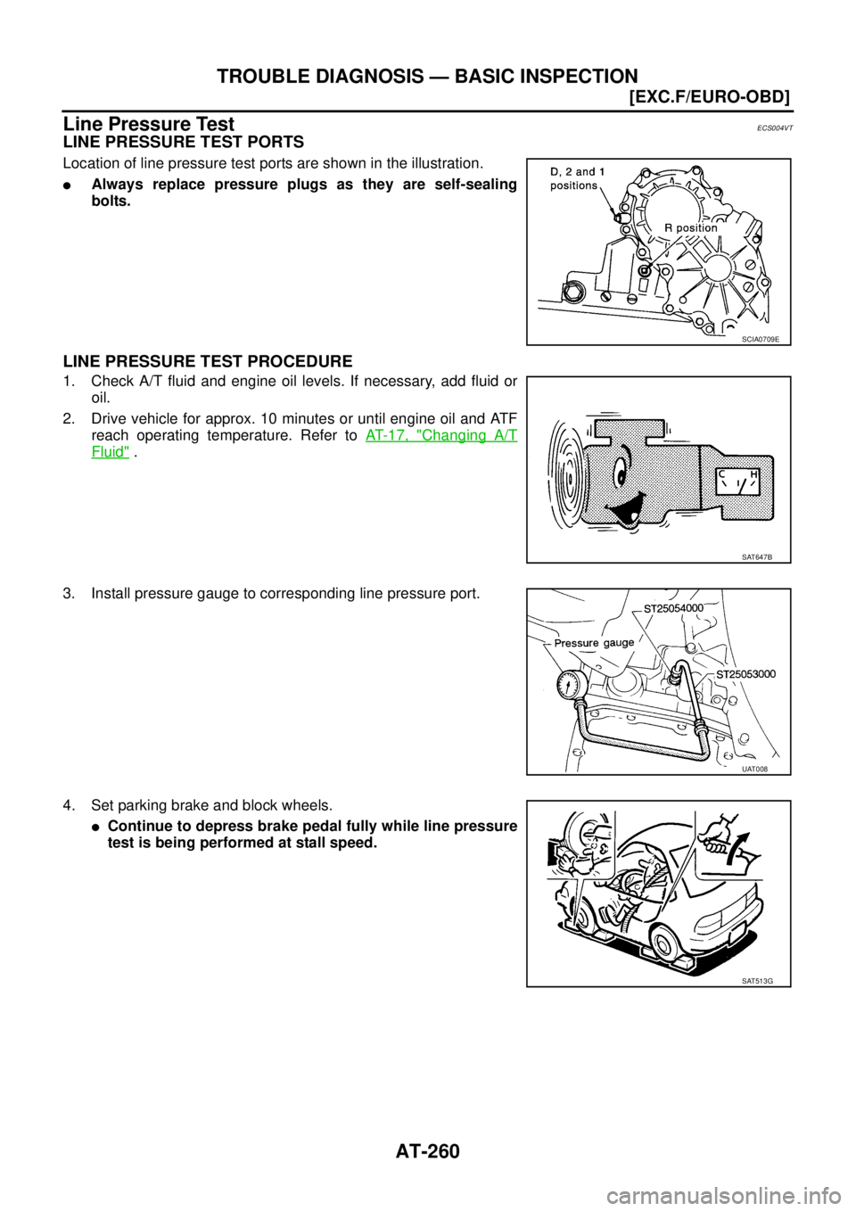
Line Pressure TestECS004VT
LINE PRESSURE TEST PORTS
Location of line pressure test ports are shown in the illustration.
�Always replace pressure plugs as they are self-sealing
bolts.
LINE PRESSURE TEST PROCEDURE
1. Check A/T fluid and engine oil levels. If necessary, add fluid or
oil.
2. Drive vehicle for approx. 10 minutes or until engine oil and ATF
reach operating temperature. Refer to AT- 1 7 , "
Changing A/T
Fluid" .
3. Install pressure gauge to corresponding line pressure port.
4. Set parking brake and block wheels.
�Continue to depress brake pedal fully while line pressure
test is being performed at stall speed.
SCIA0709E
SAT647B
UAT008
SAT513G
Page 2525 of 4555
![NISSAN X-TRAIL 2005 Service Repair Manual TROUBLE DIAGNOSIS — BASIC INSPECTION
AT-261
[EXC.F/EURO-OBD]
D
E
F
G
H
I
J
K
L
MA
B
AT
5. Start engine and measure line pressure at idle and stall speed.
�When measuring line pressure at stall spe](/manual-img/5/57403/w960_57403-2524.png "NISSAN X-TRAIL 2005 Service Repair Manual TROUBLE DIAGNOSIS — BASIC INSPECTION
AT-261
[EXC.F/EURO-OBD]
D
E
F
G
H
I
J
K
L
MA
B
AT
5. Start engine and measure line pressure at idle and stall speed.
�When measuring line pressure at stall spe")
TROUBLE DIAGNOSIS — BASIC INSPECTION
AT-261
[EXC.F/EURO-OBD]
D
E
F
G
H
I
J
K
L
MA
B
AT
5. Start engine and measure line pressure at idle and stall speed.
�When measuring line pressure at stall speed, follow the
stall test procedure.
LINE PRESSURE
JUDGEMENT OF LINE PRESSURE TEST
SAT493G
Check lock-up hold.Line pressure kPa (bar, kg/cm2 , psi)
“D”, “2” and “1” positions “R” position
Idle 500 (5.00, 5.1, 73) 778 (7.78, 7.9, 113)
Stall 1,233 (12.33, 12.6, 179) 1,918 (19.18, 19.6, 278)
Judgement Suspected parts
At idleLine pressure is low in all positions.
�Oil pump wear
�Control piston damage
�Pressure regulator valve or plug sticking
�Spring for pressure regulator valve damaged
�Fluid pressure leakage between oil strainer and pressure regulator valve
�Clogged strainer
Line pressure is low in particular posi-
tion.
�Fluid pressure leakage between manual valve and particular clutch
�For example, line pressure is:
− Low in R and 1 positions, but
− Normal in D and 2 positions.
Therefore, fluid leakage exists at or around low and reverse brake circuit.
Refer to AT- 2 3
.
Line pressure is high.
�Maladjustment of throttle position sensor
�A/T fluid temperature sensor damaged
�Line pressure solenoid valve sticking
�Short circuit of line pressure solenoid valve circuit
�Pressure modifier valve sticking
�Pressure regulator valve or plug sticking
�Open in dropping resistor circuit
At stall
speedLine pressure is low.
�Maladjustment of throttle position sensor
�Line pressure solenoid valve sticking
�Short circuit of line pressure solenoid valve circuit
�Pressure regulator valve or plug sticking
�Pressure modifier valve sticking
�Pilot valve sticking
Page 2526 of 4555
AT-262
[EXC.F/EURO-OBD]
TROUBLE DIAGNOSIS — BASIC INSPECTION
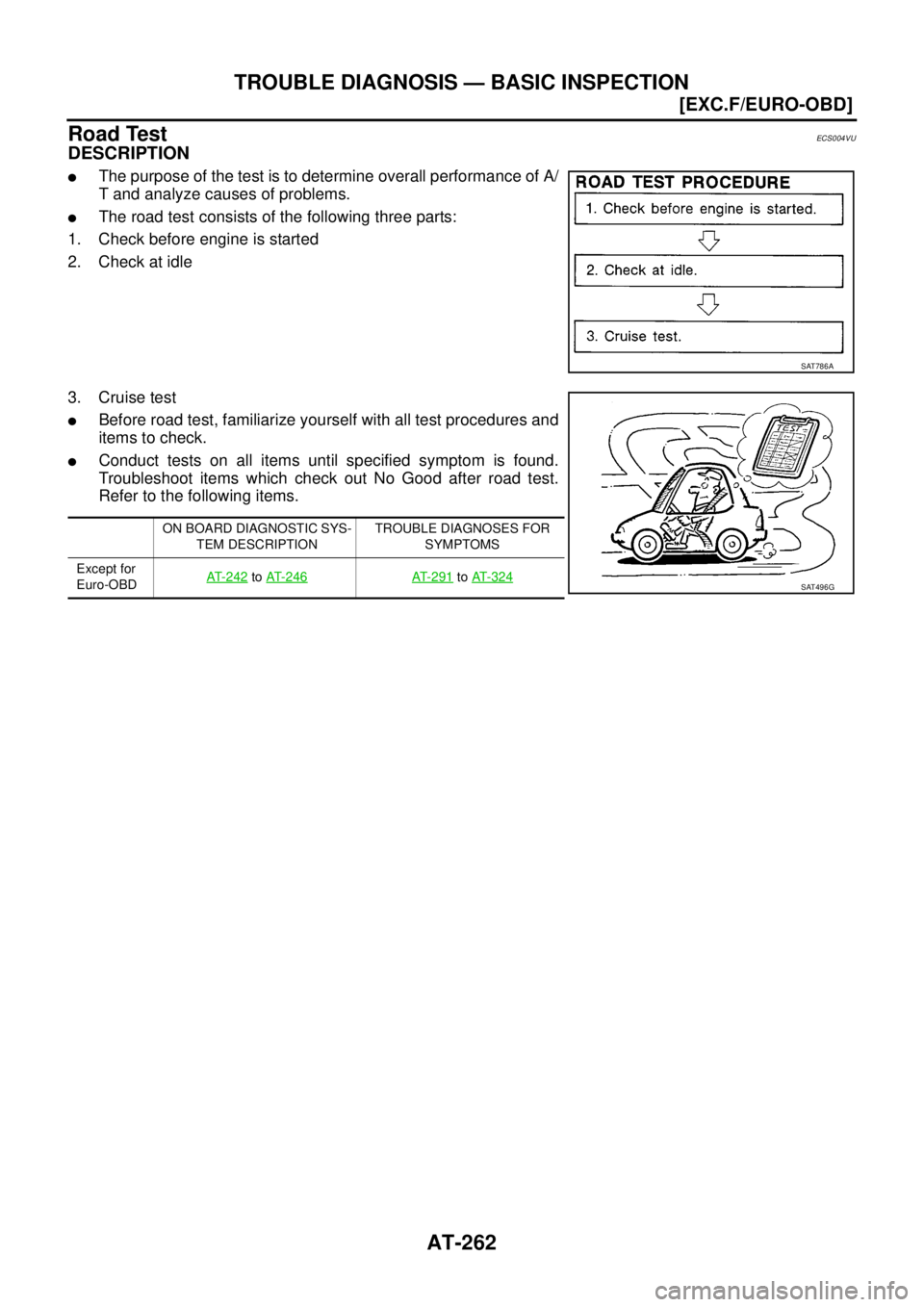
Road TestECS004VU
DESCRIPTION
�The purpose of the test is to determine overall performance of A/
T and analyze causes of problems.
�The road test consists of the following three parts:
1. Check before engine is started
2. Check at idle
3. Cruise test
�Before road test, familiarize yourself with all test procedures and
items to check.
�Conduct tests on all items until specified symptom is found.
Troubleshoot items which check out No Good after road test.
Refer to the following items.
SAT786A
ON BOARD DIAGNOSTIC SYS-
TEM DESCRIPTIONTROUBLE DIAGNOSES FOR
SYMPTOMS
Except for
Euro-OBD AT- 2 4 2
to AT-246AT-291 to AT- 3 2 4SAT496G
Page 2527 of 4555
TROUBLE DIAGNOSIS — BASIC INSPECTION
AT-263
[EXC.F/EURO-OBD]
D
E
F
G
H
I
J
K
L
MA
B
AT
1. CHECK BEFORE ENGINE IS STARTED
1. CHECK O/D OFF INDICATOR LAMP
1. Park vehicle on flat surface.
2. Move selector lever to P position.
3. Turn ignition switch to OFF position.
4. Wait 5 seconds.
5. Set overdrive control switch to ON position.
6. Turn ignition switch to ON. (Do not start engine.)
Does O/D OFF indicator lamp come on for about 2 seconds?
YES >> 1. Turn ignition switch to OFF position.
2. Perform self-diagnosis and note NG items.
Refer to AT- 2 4 6 , "
SELF-DIAGNOSTIC PROCEDURE
(WITHOUT CONSULT-II)" .
3. GO TO “2. CHECK AT IDLE”, AT- 2 6 4
.
NO >> Stop road test. GO TO “O/D OFF indicator Lamp Does
Not Come On”. AT- 2 9 1
.
SAT774B
SCIA5468E
![NISSAN X-TRAIL 2005 Service Repair Manual AT-256
[EXC.F/EURO-OBD]
TROUBLE DIAGNOSIS — BASIC INSPECTION
TROUBLE DIAGNOSIS — BASIC INSPECTIONPFP:00000
A/T Fluid CheckECS004VR
FLUID LEAKAGE CHECK
1. Clean area suspected of leaking. — for](/manual-img/5/57403/w960_57403-2519.png "NISSAN X-TRAIL 2005 Service Repair Manual AT-256
[EXC.F/EURO-OBD]
TROUBLE DIAGNOSIS — BASIC INSPECTION
TROUBLE DIAGNOSIS — BASIC INSPECTIONPFP:00000
A/T Fluid CheckECS004VR
FLUID LEAKAGE CHECK
1. Clean area suspected of leaking. — for")
![NISSAN X-TRAIL 2005 Service Repair Manual TROUBLE DIAGNOSIS — BASIC INSPECTION
AT-263
[EXC.F/EURO-OBD]
D
E
F
G
H
I
J
K
L
MA
B
AT
1. CHECK BEFORE ENGINE IS STARTED
1. CHECK O/D OFF INDICATOR LAMP
1. Park vehicle on flat surface.
2. Move se](/manual-img/5/57403/w960_57403-2526.png "NISSAN X-TRAIL 2005 Service Repair Manual TROUBLE DIAGNOSIS — BASIC INSPECTION
AT-263
[EXC.F/EURO-OBD]
D
E
F
G
H
I
J
K
L
MA
B
AT
1. CHECK BEFORE ENGINE IS STARTED
1. CHECK O/D OFF INDICATOR LAMP
1. Park vehicle on flat surface.
2. Move se")