Page 3935 of 4555
TROUBLE DIAGNOSIS
MTC-11
C
D
E
F
G
H
I
K
L
MA
B
MTC
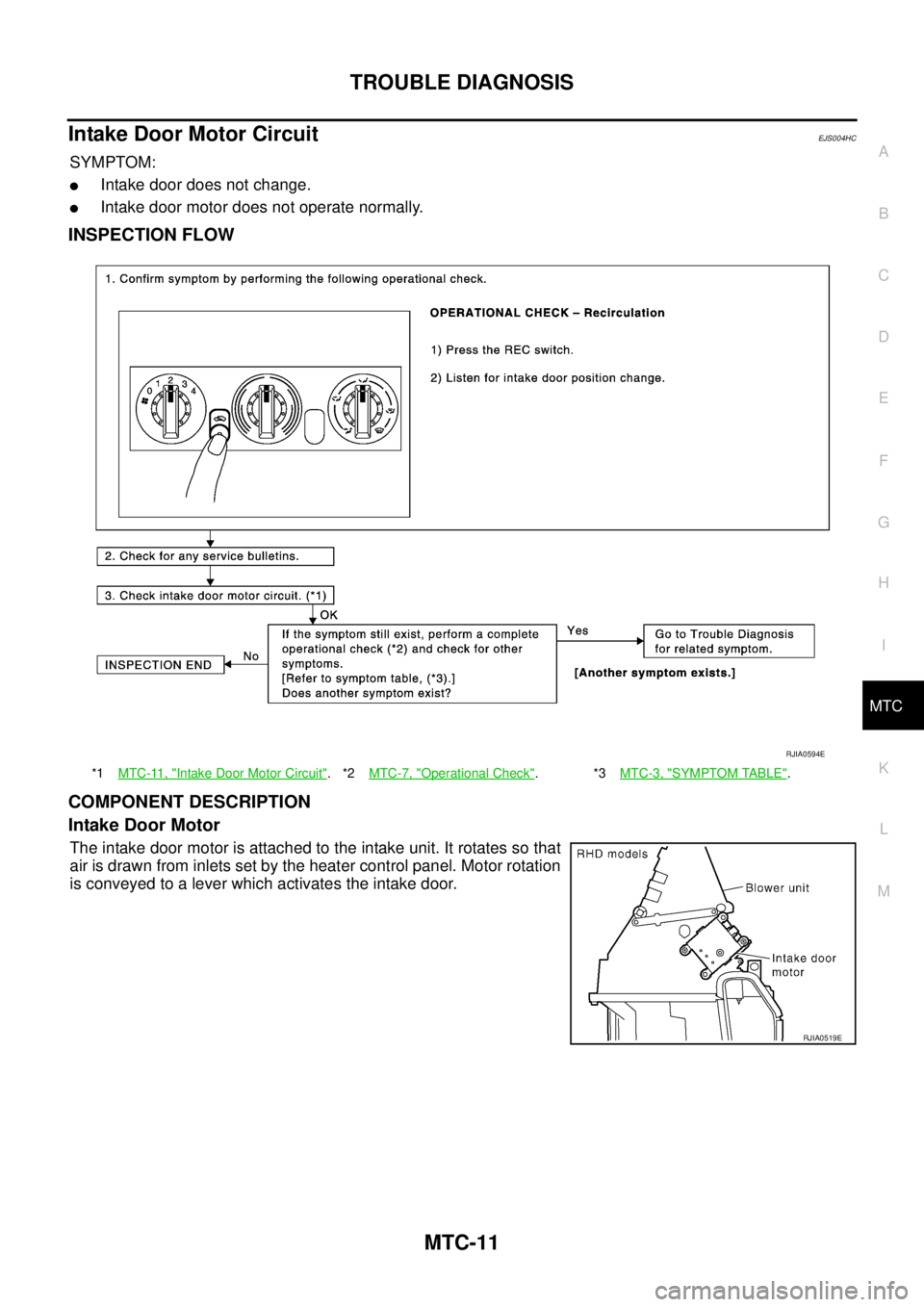
Intake Door Motor CircuitEJS004HC
SYMPTOM:
�Intake door does not change.
�Intake door motor does not operate normally.
INSPECTION FLOW
COMPONENT DESCRIPTION
Intake Door Motor
The intake door motor is attached to the intake unit. It rotates so that
air is drawn from inlets set by the heater control panel. Motor rotation
is conveyed to a lever which activates the intake door.
*1MTC-11, "Intake Door Motor Circuit".*2MTC-7, "Operational Check".*3MTC-3, "SYMPTOM TABLE".
RJIA0594E
RJIA0519E
Page 3936 of 4555

MTC-12
TROUBLE DIAGNOSIS
DIAGNOSTIC PROCEDURE FOR INTAKE DOOR MOTOR
SYMPTOM: Intake door does not operate normally.
1. CHECK POWER SUPPLY FOR HEATER CONTROL PANEL
1. Disconnect heater control panel connector.
2. Turn ignition switch ON.
3. Check voltage between heater control panel harness connector
M55 terminal 1 (BR/Y) and ground.
OK or NG
OK >> GO TO 2.
NG >> Check power supply circuit and 10 A fuse [No. 15,
located in the fuse block (J/B)]. Refer to PG-79, "
FUSE
BLOCK - JUNCTION BOX (J/B)" .
�If OK, check harness for open circuit. Repair or replace if necessary.
�If NG, replace fuse and check harness for short circuit. Repair or replace if necessary.
2. CHECK GROUND CIRCUIT FOR HEATER CONTROL PANEL
1. Turn ignition switch OFF.
2. Check continuity between heater control panel harness connec-
tor M55 terminal 5 (B) and ground.
OK or NG
OK >> GO TO 3.
NG >> Repair harness or connector.
3. CHECK RECIRCULATION SWITCH CIRCUIT
1. Press REC (recirculation) switch.
2. Check continuity between heater control panel harness connec-
tor M55 terminal 1 (BR/Y) and 5 (B).
OK or NG
OK >> GO TO 4.
NG >> Replace heater control panel.
RJIA2846E
1 – Ground : Battery voltage
RJIA2923E
5 – Ground : Continuity should exist.
RJIA2924E
1 (−) – 5 (+) : Continuity should exist.
RJIA2925E
Page 3937 of 4555
TROUBLE DIAGNOSIS
MTC-13
C
D
E
F
G
H
I
K
L
MA
B
MTC
4. CHECK POWER SUPPLY FOR INTAKE DOOR MOTOR
1. Reconnect heater control panel connector.
2. Turn ignition switch ON.
3. Check voltage between intake door motor harness connector M48 terminal 1 (Y/R: RHD models, R/W:
LHD models) and 2 (R/W: RHD models, L/R: LHD models).
OK or NG
OK >> Replace intake door motor.
NG >> GO TO 5.
ModelTerminals
Condition Voltage (+) (-)
Intake door motor
connectorTerminal No.
(wire color)Intake door motor
connectorTerminal No.
(wire color)
RHD
modelsM482 (R/W)
M481 (Y/R) REC SW: ON
Approx. 12V
1 (Y/R) 2 (R/W) REC SW: OFF
LHD
modelsM481 (R/W)
M482 (Y/R) REC SW: ON
Approx. 12V
2 (Y/R) 1 (R/W) REC SW: OFF
RJIA2847E
Page 3938 of 4555
MTC-14
TROUBLE DIAGNOSIS
5. CHECK CIRCUIT CONTINUITY BETWEEN HEATER CONTROL PANEL AND INTAKE DOOR MOTOR
1. Turn ignition switch OFF.
2. Disconnect heater control panel connector and intake door motor connector.
3. Check continuity between heater control panel harness connector M55 terminal 10 (R/W) and intake door
motor harness connector M48 terminal 2 (R/W: RHD models) or 1 (R/W: LHD models).
4. Check continuity between heater control panel harness connector M55 terminal 11 (Y/R) and intake door
motor harness connector M48 terminal 1 (Y/R: RHD models) or 2 (Y/R: LHD models).
OK or NG
OK >> Replace heater control panel.
NG >> Repair harness or connector.
Te r m i n a l s
Continuity Heater control panel connec-
torIntake door motor connector
ConnectorTerminal No.
(wire color)ConnectorTerminal No.
(wire color)
M55 10 (R/W) M48 2 (R/W): RHD models
Ye s 1 (R/W): LHD models
M55 11 (Y/R) M48 1 (Y/R): RHD models
2 (Y/R): LHD models
RJIA3145E
Page 3941 of 4555

TROUBLE DIAGNOSIS
MTC-17
C
D
E
F
G
H
I
K
L
MA
B
MTC
4. CHECK CIRCUIT CONTINUITY BETWEEN BLOWER MOTOR AND FAN RESISTOR
1. Disconnect fan resistor connector.
2. Check continuity between fan resistor harness connector M66
terminal 1 (L/B) and blower motor harness connector M65 termi-
nal 2 (L/B).
OK or NG
OK >> GO TO 5.
NG >> Repair harness or connector.
5. CHECK FAN RESISTOR
Refer to MTC-18, "
Fan Resistor" .
OK or NG
OK >> GO TO 6.
NG >> Replace fan resistor.
6. CHECK CIRCUIT CONTINUITY BETWEEN FAN RESISTOR AND HEATER CONTROL PANEL
1. Disconnect heater control panel connector.
2. Check continuity between fan resistor harness connector M66
terminal 2 (L/R), 3 (L/Y) or 4 (L/W) and heater control panel har-
ness connector M54 terminal 14 (L/W), 15 (L/Y) or 16 (L/R).
OK or NG
OK >> GO TO 7.
NG >> Repair harness or connector.
7. CHECK CIRCUIT CONTINUITY BETWEEN BLOWER MOTOR AND HEATER CONTROL PANEL
Check continuity between blower motor harness connector M65 ter-
minal 2 (L/B) and heater control panel harness connector M54 termi-
nal 17 (L/B).
OK or NG
OK >> GO TO 8.
NG >> Repair harness or connector.
8. CHECK FAN SWITCH
Refer to MTC-18, "
Fan Switch" .
OK or NG
OK >> GO TO 9.
NG >> Replace fan switch.1 – 2 : Continuity should exist.
RJIA2931E
2 – 16 : Continuity should exist.
3 – 15 : Continuity should exist.
4 – 14 : Continuity should exist.
RJIA2932E
2 – 17 : Continuity should exist.
RJIA2933E
Page 3942 of 4555
MTC-18
TROUBLE DIAGNOSIS
9. CHECK GROUND CIRCUIT
Check continuity between heater control panel harness connector
M54 terminal 13 (B) and ground.
OK or NG
OK >> INSPECTION END
NG >> Repair harness or connector.
COMPONENT INSPECTION
Blower Motor
Confirm smooth rotation of the blower motor.
�Ensure that there are no foreign particles inside the intake unit.
Fan Switch
Check continuity between heater control connector M54 terminals at
each switch position.
Fan Resistor
Check resistance between fan resister connector M66 terminals.13 – Ground : Continuity should exist.
RJIA2934E
RJIA0609E
Switch position Terminals Continuity
OFF 13 - 14, 15, 16, 17 No
1 13 - 14
Ye s 2 13 - 15
3 13 - 16
4 13 - 17
RJIA0610E
TerminalsResistance (Ω)
LHD RHD
12 0.25 - 0.31 0.28 - 0.34
3 0.58 - 0.70 0.79 - 0.97
4 1.33 - 1.63 1.84 - 2.24
RJIA0611E
Page 3945 of 4555
CONTROLLER
MTC-21
C
D
E
F
G
H
I
K
L
MA
B
MTC
CONTROLLERPFP:27500
Removal and InstallationEJS004HA
REMOVAL
1. Remove mode door cable and air mix door cable from heater unit. Refer to MTC-31, "MODE DOOR" and
MTC-32, "
AIR MIX DOOR" .
2. Remove cluster lid C. Refer to IP-11, "
Removal and Installation" .
3. Remove mounting screws from heater control panel.
4. Remove heater control panel, and then remove heater control
panel connector.
INSTALLATION
Installation is basically the reverse order of removal.
Disassembly and AssemblyEJS004HB
RJIA0089E
1. Mode door cable 2. Clamp 3. Case assembly
4. Heater panel 5. Finisher 6. Dial
7. Air mix door cable 8. Fan switch 9. Bulb
RJIA3153E
Page 3951 of 4555
HEATER UNIT
MTC-27
C
D
E
F
G
H
I
K
L
MA
B
MTC
HEATER UNITPFP:27100
Removal and InstallationEJS001F9
REMOVAL
1. Drain coolant from cooling system. Refer to CO-9, "Changing Engine Coolant" for QR engine or CO-32,
"Changing Engine Coolant" for YD engine.
2. Disconnect two heater hoses from heater core pipe.
3. Remove instrument panel. Refer to IP-11, "
Removal and Installation" .
4. Remove blower unit. Refer to MTC-22, "
BLOWER UNIT" .
5. Remove clips of vehicle harness from steering member.
6. Remove mounting nuts, and then remove instrument stay.
7. Remove mounting bolts from heater (& cooling) unit.
RJIA0060E
RJIA0061E
RJIA2444E


 and ground.
OK or NG
OK >> INSPECTION END
NG >> Repair harness or")

