Page 2050 of 4555
![NISSAN X-TRAIL 2005 Service Repair Manual EC-1646
[YD (WITHOUT EURO-OBD)]
GLOW CONTROL SYSTEM
Diagnostic ProcedureEBS0125J
1. INSPECTION START
Check fuel level, fuel supplying system, starter motor, etc.
OK or NG
OK >> GO TO 2.
NG >> Correc](/manual-img/5/57403/w960_57403-2049.png "NISSAN X-TRAIL 2005 Service Repair Manual EC-1646
[YD (WITHOUT EURO-OBD)]
GLOW CONTROL SYSTEM
Diagnostic ProcedureEBS0125J
1. INSPECTION START
Check fuel level, fuel supplying system, starter motor, etc.
OK or NG
OK >> GO TO 2.
NG >> Correc")
EC-1646
[YD (WITHOUT EURO-OBD)]
GLOW CONTROL SYSTEM
Diagnostic ProcedureEBS0125J
1. INSPECTION START
Check fuel level, fuel supplying system, starter motor, etc.
OK or NG
OK >> GO TO 2.
NG >> Correct.
2. CHECK INSTALLATION
Check that glow plug nut and all glow plug connecting plate nuts are
installed properly.
OK or NG
OK >> GO TO 3.
NG >> Install properly.
3. CHECK GLOW INDICATOR LAMP OPERATION
With CONSULT-II
1. Turn ignition switch ON.
2. Select “COOLAN TEMP/S” in “DATA MONITOR” mode with
CONSULT-II.
3. Confirm that “COOLAN TEMP/S” indicates below 80°C (176°F).
If it indicates above 80°C (176°F), cool down engine.
4. Turn ignition switch OFF, wait at least 5 seconds and then turn
ON.
5. Make sure that glow indicator lamp is turned ON for 1.5 seconds
or more after turning ignition switch ON, and then glow indicator
lamp turned OFF.
Without CONSULT-II
1. Set the tester probe between ECM terminal 51 (engine coolant
temperature sensor signal) and ground.
2. Confirm that the voltage indicates above 1.53V. If it indicates
below 1.53V, cool down engine.
3. Turn ignition switch OFF, wait at least 5 seconds and then turn
ON.
4. Make sure that glow indicator lamp is turned ON for 1.5 seconds
or more after turning ignition switch ON, and then glow indicator
lamp turned OFF.
OK or NG
OK >> GO TO 4.
NG >> GO TO 5.
SEF392YA
SEF013Y
PBIB2216E
Page 2051 of 4555
![NISSAN X-TRAIL 2005 Service Repair Manual GLOW CONTROL SYSTEM
EC-1647
[YD (WITHOUT EURO-OBD)]
C
D
E
F
G
H
I
J
K
L
MA
EC
4. CHECK GLOW CONTROL SYSTEM OVERALL FUNCTION
With CONSULT-ll
1. Select “COOLAN TEMP/S” in “DATA MONITOR” mode](/manual-img/5/57403/w960_57403-2050.png "NISSAN X-TRAIL 2005 Service Repair Manual GLOW CONTROL SYSTEM
EC-1647
[YD (WITHOUT EURO-OBD)]
C
D
E
F
G
H
I
J
K
L
MA
EC
4. CHECK GLOW CONTROL SYSTEM OVERALL FUNCTION
With CONSULT-ll
1. Select “COOLAN TEMP/S” in “DATA MONITOR” mode")
GLOW CONTROL SYSTEM
EC-1647
[YD (WITHOUT EURO-OBD)]
C
D
E
F
G
H
I
J
K
L
MA
EC
4. CHECK GLOW CONTROL SYSTEM OVERALL FUNCTION
With CONSULT-ll
1. Select “COOLAN TEMP/S” in “DATA MONITOR” mode with
CONSULT-II.
2. Confirm that “COOLAN TEMP/S” indicates approximately 25°C
(77°F). If NG, cool down engine.
3. Turn ignition switch OFF.
4. Set voltmeter probe between glow plug and engine body.
5. Turn ignition switch ON.
6. Check the voltage between glow plug and engine body under
the following conditions.
Without CONSULT-II
1. Set the tester probe between ECM terminal 51 (engine coolant
temperature sensor signal) and ground.
2. Confirm that the voltage indicates approximately 3.62V. If NG,
cool down engine.
3. Turn ignition switch OFF.
4. Set voltmeter probe between glow plug and engine body.
5. Turn ignition switch ON.
6. Check the voltage between glow plug and engine body under
the following conditions.
OK or NG
OK >>INSPECTION END
NG >> GO TO 7.
SEF013Y
Conditions Voltage
For 20 seconds after turning ignition switch ON Battery voltage
More than 20 seconds after turning ignition
switch ONApprox. 0V
PBIB0425E
PBIB2216E
Conditions Voltage
For 20 seconds after turning ignition switch ON Battery voltage
More than 20 seconds after turning ignition
switch ONApprox. 0V
PBIB0425E
Page 2052 of 4555
EC-1648
[YD (WITHOUT EURO-OBD)]
GLOW CONTROL SYSTEM
5. CHECK DTC
Check that DTC U1000 is not displayed.
Ye s o r N o
Yes >> Perform trouble diagnoses for DTC U1000, refer to EC-1425, "DTC U1000 CAN COMMUNICA-
TION LINE" .
No >> GO TO 6.
6. CHECK COMBINATON METER OPERATION
Does combination meter operate normally?
Ye s o r N o
Yes >> GO TO 14.
No >> Check combination meter circuit. Refer to DI-4, "
COMBINATION METERS" .
7. CHECK GLOW RELAY POWER SUPPLY CIRCUIT
1. Turn ignition switch OFF.
2. Disconnect glow relay.
3. Check voltage between glow relay terminals 1, 3 and ground
with CONSULT-II or tester.
OK or NG
OK >> GO TO 9.
NG >> GO TO 8.
8. DETECT MALFUNCTIONING PART
Check the following.
�60A fusible link
�Harness for open or short between glow relay and battery
>> Repair harness or connectors.
MBIB0078E
Voltage: Battery voltage
PBIB1413E
Page 2053 of 4555
![NISSAN X-TRAIL 2005 Service Repair Manual GLOW CONTROL SYSTEM
EC-1649
[YD (WITHOUT EURO-OBD)]
C
D
E
F
G
H
I
J
K
L
MA
EC
9. CHECK GLOW RELAY OUTPUT SIGNAL CIRCUIT FOR OPEN AND SHORT
1. Disconnect ECM harness connector.
2. Check harness conti](/manual-img/5/57403/w960_57403-2052.png "NISSAN X-TRAIL 2005 Service Repair Manual GLOW CONTROL SYSTEM
EC-1649
[YD (WITHOUT EURO-OBD)]
C
D
E
F
G
H
I
J
K
L
MA
EC
9. CHECK GLOW RELAY OUTPUT SIGNAL CIRCUIT FOR OPEN AND SHORT
1. Disconnect ECM harness connector.
2. Check harness conti")
GLOW CONTROL SYSTEM
EC-1649
[YD (WITHOUT EURO-OBD)]
C
D
E
F
G
H
I
J
K
L
MA
EC
9. CHECK GLOW RELAY OUTPUT SIGNAL CIRCUIT FOR OPEN AND SHORT
1. Disconnect ECM harness connector.
2. Check harness continuity between ECM terminal 37 and glow relay terminal 2.
Refer to Wiring Diagram.
3. Also check harness for short to ground and short to power.
OK or NG
OK >> GO TO 11.
NG >> GO TO 10.
10. DETECT MALFUNCTIONING PART
Check the following.
�Harness connectors E64, F5
�Harness for open or short between glow relay and ECM
>> Repair open circuit or short to ground or short to power in harness or connectors.
11 . CHECK HARNESS CONTINUITY BETWEEN GLOW RELAY AND GLOW PLUG FOR OPEN AND
SHORT
1. Disconnect glow plug harness connector.
2. Check harness continuity between glow relay terminal 5 and glow plug harness connector.
Refer to Wiring Diagram.
3. Also check harness for short to ground and short to power.
OK or NG
OK >> GO TO 12.
NG >> Repair open circuit or short to ground or short to power in harness or connectors.
12. CHECK GLOW RELAY
Refer to EC-1650, "
Component Inspection" .
OK or NG
OK >> GO TO 13.
NG >> Replace glow relay.
13. CHECK GLOW PLUG
Refer to EC-1650, "
Component Inspection" .
OK or NG
OK >> GO TO 14.
NG >> Replace glow plug.
14. CHECK INTERMITTENT INCIDENT
Refer to EC-1414, "
TROUBLE DIAGNOSIS FOR INTERMITTENT INCIDENT" .
>>INSPECTION END Continuity should exist.
Continuity should exist.
Page 2054 of 4555
EC-1650
[YD (WITHOUT EURO-OBD)]
GLOW CONTROL SYSTEM
Component InspectionEBS0125K
GLOW RELAY
Check continuity between glow relay terminals 3 and 5 under the fol-
lowing conditions.
Operation takes less than 1 second.
GLOW PLUG
1. Remove glow plug connecting plate.
2. Check glow plug resistance.
NOTE:
�Do not bump glow plug heating element. If it is bumped,
replace glow plug with a new one.
�If glow plug is dropped from a height of 10 cm (3.94 in) or
higher, replace with a new one.
�If glow plug installation hole is contaminated with car-
bon, remove it with a reamer or suitable tool.
�Hand-tighten glow plug by turning it two or three times,
then tighten using a tool to specified torque.
Removal and InstallationEBS0125L
GLOW PLUG
Refer to EM-162, "GLOW PLUG" .
Conditions Continuity
12V direct current supply between ter-
minals 1 and 2Ye s
No current supply No
PBIB0428E
Resistance: Approximately 0.8 Ω [at 25°C (77°F)]
: 20.1 N-m (2.1 kg-m, 15 ft-lb)
PBIB0429E
Page 2059 of 4555
EGR VOLUME CONTROL SYSTEM
EC-1655
[YD (WITHOUT EURO-OBD)]
C
D
E
F
G
H
I
J
K
L
MA
EC
Diagnostic ProcedureEBS0125Q
1. CHECK EGR VOLUME CONTROL SYSTEM OVERALL FUNCTION
1. Turn ignition switch OFF.
2. Set the oscilloscope probe between ECM terminals 25, 26, 27, 28 and ground.
3. Start engine and let it idle.
4. Check the oscilloscope screen when revving engine up to 3,200 rpm and return to idle.
OK or NG
OK >>INSPECTION END
NG >> GO TO 2.
2. CHECK EGR VOLUME CONTROL VALVE POWER SUPPLY CIRCUIT-I
1. Turn ignition switch OFF.
2. Disconnect EGR volume control valve harness connector.
3. Turn ignition switch ON.
4. Check voltage between EGR volume control valve terminals 2, 5
and ground with CONSULT-II or tester.
OK or NG
OK >> GO TO 4.
NG >> GO TO 3.The pulse signal as shown in the figure should appear.
MBIB0617E
PBIB1901E
Voltage: Battery voltage
PBIB2013E
Page 2060 of 4555
![NISSAN X-TRAIL 2005 Service Repair Manual EC-1656
[YD (WITHOUT EURO-OBD)]
EGR VOLUME CONTROL SYSTEM
3. DETECT MALFUNCTIONING PART
Check the following.
�Harness connectors F30, M63
�Harness for open or short between EGR volume control valve](/manual-img/5/57403/w960_57403-2059.png "NISSAN X-TRAIL 2005 Service Repair Manual EC-1656
[YD (WITHOUT EURO-OBD)]
EGR VOLUME CONTROL SYSTEM
3. DETECT MALFUNCTIONING PART
Check the following.
�Harness connectors F30, M63
�Harness for open or short between EGR volume control valve")
EC-1656
[YD (WITHOUT EURO-OBD)]
EGR VOLUME CONTROL SYSTEM
3. DETECT MALFUNCTIONING PART
Check the following.
�Harness connectors F30, M63
�Harness for open or short between EGR volume control valve and ECM
�Harness for open or short between EGR volume control valve and ECM relay
>> Repair open circuit or short to ground or short to power in harness or connectors.
4. CHECK EGR VOLUME CONTROL VALVE OUTPUT SIGNAL CIRCUIT FOR OPEN AND SHORT
1. Turn ignition switch OFF.
2. Disconnect ECM harness connector.
3. Check harness continuity between ECM terminals and EGR volume control valve terminals as follows.
Refer to Wiring Diagram.
4. Also check harness for short to ground and short to power.
OK or NG
OK >> GO TO 5.
NG >> Repair open circuit or short to ground or short to power in harness or connectors.
5. CHECK EGR VOLUME CONTROL VALVE
Refer to EC-1656, "
Component Inspection" .
OK or NG
OK >> GO TO 6.
NG >> Replace EGR volume control valve.
6. CHECK EGR PASSAGE
Check the following for clogging and cracks.
�EGR tube
�EGR hose
�EGR cooler
OK or NG
OK >> GO TO 7.
NG >> Repair or replace EGR passage.
7. CHECK INTERMITTENT INCIDENT
Refer to EC-1414, "
TROUBLE DIAGNOSIS FOR INTERMITTENT INCIDENT" .
>>INSPECTION END
Component InspectionEBS0125R
EGR VOLUME CONTROL VALVE
With CONSULT-II
1. Disconnect EGR volume control valve harness connector.
ECM terminal EGR volume control valve terminal
25 1
26 6
27 3
28 4
Continuity should exist.
Page 2061 of 4555
EGR VOLUME CONTROL SYSTEM
EC-1657
[YD (WITHOUT EURO-OBD)]
C
D
E
F
G
H
I
J
K
L
MA
EC
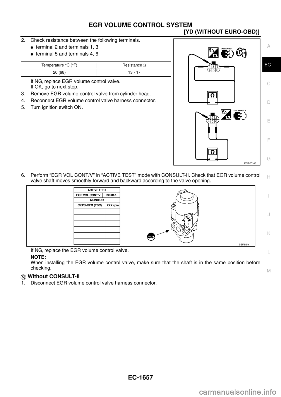
2. Check resistance between the following terminals.
�terminal 2 and terminals 1, 3
�terminal 5 and terminals 4, 6
If NG, replace EGR volume control valve.
If OK, go to next step.
3. Remove EGR volume control valve from cylinder head.
4. Reconnect EGR volume control valve harness connector.
5. Turn ignition switch ON.
6. Perform “EGR VOL CONT/V” in “ACTIVE TEST” mode with CONSULT-II. Check that EGR volume control
valve shaft moves smoothly forward and backward according to the valve opening.
If NG, replace the EGR volume control valve.
NOTE:
When installing the EGR volume control valve, make sure that the shaft is in the same position before
checking.
Without CONSULT-II
1. Disconnect EGR volume control valve harness connector.
Temperature °C (°F) Resistance Ω
20 (68) 13 - 17
PBIB2014E
SEF819Y
![NISSAN X-TRAIL 2005 Service Repair Manual EC-1648
[YD (WITHOUT EURO-OBD)]
GLOW CONTROL SYSTEM
5. CHECK DTC
Check that DTC U1000 is not displayed.
Ye s o r N o
Yes >> Perform trouble diagnoses for DTC U1000, refer to EC-1425, "DTC U1000 CA](/manual-img/5/57403/w960_57403-2051.png "NISSAN X-TRAIL 2005 Service Repair Manual EC-1648
[YD (WITHOUT EURO-OBD)]
GLOW CONTROL SYSTEM
5. CHECK DTC
Check that DTC U1000 is not displayed.
Ye s o r N o
Yes >> Perform trouble diagnoses for DTC U1000, refer to EC-1425, \"DTC U1000 CA")
![NISSAN X-TRAIL 2005 Service Repair Manual EC-1650
[YD (WITHOUT EURO-OBD)]
GLOW CONTROL SYSTEM
Component InspectionEBS0125K
GLOW RELAY
Check continuity between glow relay terminals 3 and 5 under the fol-
lowing conditions.
Operation takes le](/manual-img/5/57403/w960_57403-2053.png "NISSAN X-TRAIL 2005 Service Repair Manual EC-1650
[YD (WITHOUT EURO-OBD)]
GLOW CONTROL SYSTEM
Component InspectionEBS0125K
GLOW RELAY
Check continuity between glow relay terminals 3 and 5 under the fol-
lowing conditions.
Operation takes le")
![NISSAN X-TRAIL 2005 Service Repair Manual EGR VOLUME CONTROL SYSTEM
EC-1655
[YD (WITHOUT EURO-OBD)]
C
D
E
F
G
H
I
J
K
L
MA
EC
Diagnostic ProcedureEBS0125Q
1. CHECK EGR VOLUME CONTROL SYSTEM OVERALL FUNCTION
1. Turn ignition switch OFF.
2. S](/manual-img/5/57403/w960_57403-2058.png "NISSAN X-TRAIL 2005 Service Repair Manual EGR VOLUME CONTROL SYSTEM
EC-1655
[YD (WITHOUT EURO-OBD)]
C
D
E
F
G
H
I
J
K
L
MA
EC
Diagnostic ProcedureEBS0125Q
1. CHECK EGR VOLUME CONTROL SYSTEM OVERALL FUNCTION
1. Turn ignition switch OFF.
2. S")