Page 2109 of 4555
![NISSAN X-TRAIL 2005 Service Repair Manual FUEL SYSTEM
FL-3
[QR]
C
D
E
F
G
H
I
J
K
L
MA
FL
FUEL SYSTEMPFP:17503
Checking Fuel LinesEBS00KOS
Inspect fuel lines, filler cap and tank for improper attachment, leaks,
cracks, damage, loose connect](/manual-img/5/57403/w960_57403-2108.png "NISSAN X-TRAIL 2005 Service Repair Manual FUEL SYSTEM
FL-3
[QR]
C
D
E
F
G
H
I
J
K
L
MA
FL
FUEL SYSTEMPFP:17503
Checking Fuel LinesEBS00KOS
Inspect fuel lines, filler cap and tank for improper attachment, leaks,
cracks, damage, loose connect")
FUEL SYSTEM
FL-3
[QR]
C
D
E
F
G
H
I
J
K
L
MA
FL
FUEL SYSTEMPFP:17503
Checking Fuel LinesEBS00KOS
Inspect fuel lines, filler cap and tank for improper attachment, leaks,
cracks, damage, loose connections, chafing or deterioration.
If necessary, repair or replace damaged parts.
General PrecautionsEBS011T7
WARNING:
When replacing fuel line parts, be sure to observe the following.
�Put a “CAUTION: INFLAMMABLE” sign in the workshop.
�Be sure to work in a well ventilated area and furnish workshop with a CO2 fire extinguisher.
�Do not smoke while servicing fuel system. Keep open flames and sparks away from the work area.
CAUTION:
�Use gasoline required by the regulations for octane number. Refer to GI-5, "Precautions for Fuel" .
�Before removing fuel line parts, perform the following procedures:
–Put drained fuel in an explosion-proof container and put the lid on securely. Keep the container in
safe area.
–Release fuel pressure from the fuel lines. Refer to EC-49, "FUEL PRESSURE RELEASE" (WITH
EURO-OBD) or EC-562, "
FUEL PRESSURE RELEASE" (WITHOUT EURO-OBD).
–Disconnect the battery cable from the negative terminal.
�Always replace O-rings and clamps with new ones.
�Do not kink or twist tubes when they are being installed.
�Do not tighten hose clamps excessively to avoid damaging hoses.
�After connecting fuel tube quick connectors, make sure
quick connectors are secure.
Ensure that connector and resin tube do not contact any
adjacent parts.
�After installing tubes, check if there are no fuel leaks at con-
nections in the following steps.
–Apply fuel pressure to fuel lines with turning ignition switch
“ON” (with engine stopped). Then check for fuel leaks at
connections.
–Start engine and rev it up and check for fuel leaks at con-
nections.
�For servicing “Evaporative Emission System” parts, refer to
EC-522, "
EVAPORATIVE EMISSION SYSTEM" (WITH EURO-
ODB) or EC-962, "
EVAPORATIVE EMISSION SYSTEM"
(WITHOUT EURO-OBD).
SMA803A
SBIA0504E
Page 2110 of 4555
![NISSAN X-TRAIL 2005 Service Repair Manual FL-4
[QR]
FUEL LEVEL SENSOR UNIT, FUEL FILTER AND FUEL PUMP ASSEMBLY
FUEL LEVEL SENSOR UNIT, FUEL FILTER AND FUEL PUMP ASSEMBLYPFP:17042
Removal and InstallationEBS00KOU
REMOVAL
WARNING:
Be sure to](/manual-img/5/57403/w960_57403-2109.png "NISSAN X-TRAIL 2005 Service Repair Manual FL-4
[QR]
FUEL LEVEL SENSOR UNIT, FUEL FILTER AND FUEL PUMP ASSEMBLY
FUEL LEVEL SENSOR UNIT, FUEL FILTER AND FUEL PUMP ASSEMBLYPFP:17042
Removal and InstallationEBS00KOU
REMOVAL
WARNING:
Be sure to")
FL-4
[QR]
FUEL LEVEL SENSOR UNIT, FUEL FILTER AND FUEL PUMP ASSEMBLY
FUEL LEVEL SENSOR UNIT, FUEL FILTER AND FUEL PUMP ASSEMBLYPFP:17042
Removal and InstallationEBS00KOU
REMOVAL
WARNING:
Be sure to read “General Precautions” when working on the fuel system. Refer to FL-3, "
General Pre-
cautions" .
1. Check fuel level on fuel gauge. If gauge indicates more than the
level as shown in the figure (full or almost full), drain fuel from
fuel tank until gauge indicates level as shown in the figure or
below.
NOTE:
Fuel will be spilled when removing main and sub fuel level sen-
sor units for the top of the fuel is above the main and sub fuel
level sensor units installation surface.
�As a guide, fuel level becomes the position as shown in the
figure or below when approximately 15 (3-1/4 Imp gal) of
fuel are drained from fuel tank.
�In case fuel pump does not operate, perform the following
procedure.
a. Insert fuel tube of less than 25 mm (0.98 in) in diameter into fuel filler tube through fuel filler opening to
draw fuel from fuel filler tube.
b. Disconnect fuel filler hose from fuel filler tube. Refer to FL-11, "
FUEL TANK" .
c. Insert fuel tube into fuel tank through fuel filler hose to draw fuel from fuel tank.
2. Release the fuel pressure from the fuel lines. Refer to EC-49, "
FUEL PRESSURE RELEASE" (WITH
EURO-OBD) or EC-562, "
FUEL PRESSURE RELEASE" (WITHOUT EURO-OBD).
3. Open fuel filler lid.
4. Open fuel filler cap and release the pressure inside fuel tank.
5. Lift to hold rear seat cushion up. Refer to SE-32, "
REAR SEAT" .
1. Lock ring 2.Main fuel level sensor unit, fuel filter
and fuel pump assembly3.Jet pump, fuel hose and jet pump
inlet assembly
4. Chamber 5. Seal packing 6. Sub fuel level sensor unit
PBIC2257E
PBIC3641E
Page 2113 of 4555
![NISSAN X-TRAIL 2005 Service Repair Manual FUEL LEVEL SENSOR UNIT, FUEL FILTER AND FUEL PUMP ASSEMBLY
FL-7
[QR]
C
D
E
F
G
H
I
J
K
L
MA
FL
a. Removal of main fuel level sensor unit, fuel filter and fuel pump
assembly:
i. Raise main fuel level](/manual-img/5/57403/w960_57403-2112.png "NISSAN X-TRAIL 2005 Service Repair Manual FUEL LEVEL SENSOR UNIT, FUEL FILTER AND FUEL PUMP ASSEMBLY
FL-7
[QR]
C
D
E
F
G
H
I
J
K
L
MA
FL
a. Removal of main fuel level sensor unit, fuel filter and fuel pump
assembly:
i. Raise main fuel level")
FUEL LEVEL SENSOR UNIT, FUEL FILTER AND FUEL PUMP ASSEMBLY
FL-7
[QR]
C
D
E
F
G
H
I
J
K
L
MA
FL
a. Removal of main fuel level sensor unit, fuel filter and fuel pump
assembly:
i. Raise main fuel level sensor unit, fuel filter and fuel pump
assembly, and disconnect jet pump.
ii. Leave jet pump on fuel tank with fuel hose.
CAUTION:
Do not disconnect jet pump and fuel hose.
iii. If necessary, remove chamber from the bottom of fuel tank by
sliding toward the rear of the vehicle.
b. Removal of sub fuel level sensor unit:
i. Raise and release sub fuel level sensor unit to remove.
ii. If necessary, remove jet pump inlet from the bottom of fuel tank by pinching tabs.
CAUTION:
Do not separate jet pump inlet and fuel hose.
INSPECTION AFTER REMOVAL
Make sure that fuel pump strainer is free from foreign materials. If any are found, remove them.
INSTALLATION
Note the following, and install in the reverse order of removal.
Chamber and Jet Pump
When installing chamber and jet pump, insert them fully until a click
sound of full stopper engagement is heard (Ditto for jet pump inlet).
Main and Sub Fuel Level Sensor Unit
1. Install seal packing to fuel tank without any twist.
2. Face fuel level sensor unit, fuel filter and fuel pump assembly as
shown in the figure, and install it to fuel tank. (Figure shows left
side of fuel tank.)
CAUTION:
Do not bend float arm during installing.
NOTE:
On right side of fuel tank, there are three carved lines on fuel
tank. Set mating mark between two outer carved lines.
3. Tighten rock ring with rock ring wrench (commercial service tool).
CAUTION:
Install rock ring horizontally.
Quick Connector
Connect quick connector as follows:
1. Check the connection for damage and foreign materials.
KBIA0281E
KBIA0302E
KBIA0282E
Page 2114 of 4555
![NISSAN X-TRAIL 2005 Service Repair Manual FL-8
[QR]
FUEL LEVEL SENSOR UNIT, FUEL FILTER AND FUEL PUMP ASSEMBLY
2. Align the connector with the tube, then insert the connector straight into the tube until a click sound is
heard.
3. After con](/manual-img/5/57403/w960_57403-2113.png "NISSAN X-TRAIL 2005 Service Repair Manual FL-8
[QR]
FUEL LEVEL SENSOR UNIT, FUEL FILTER AND FUEL PUMP ASSEMBLY
2. Align the connector with the tube, then insert the connector straight into the tube until a click sound is
heard.
3. After con")
FL-8
[QR]
FUEL LEVEL SENSOR UNIT, FUEL FILTER AND FUEL PUMP ASSEMBLY
2. Align the connector with the tube, then insert the connector straight into the tube until a click sound is
heard.
3. After connecting, make sure that the connection is secure by following method.
�Visually confirm that the two tabs are connected to the connector.
�Pull the tube and the connector to make sure they are
securely connected.
Inspection Hole Cover
1. Install inspection hole covers with the front mark (arrow) facing front of the vehicle.
2. Lock clips by turning counterclockwise by 90 degrees.
INSPECTION AFTER INSTALLATION
Use the following procedure to check for fuel leaks.
1. Turn ignition switch “ON” (with engine stopped), then check connections for leaks by applying fuel pres-
sure to fuel piping.
2. Start engine and let it idle and make sure there are no fuel leaks at the fuel system connections.
Disassembly and AssemblyEBS00KOV
CAUTION:
Sub fuel level sensor unit cannot be disassembled and should be replaced as a unit.
DISASSEMBLY
1. Separate fuel pump and bracket from fuel filter as follows:
PBIC1653E
1. Fuel filter 2. O-ring 3. Clip
4. Pressure regulator 5. O-ring 6. Fuel level sensor unit
7. Bracket 8. Rubber 9. Fuel pump
10. Packing
PBIC2259E
Page 2116 of 4555
FL-10
[QR]
FUEL LEVEL SENSOR UNIT, FUEL FILTER AND FUEL PUMP ASSEMBLY
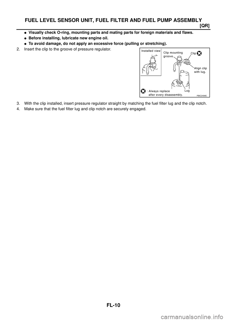
�Visually check O-ring, mounting parts and mating parts for foreign materials and flaws.
�Before installing, lubricate new engine oil.
�To avoid damage, do not apply an excessive force (pulling or stretching).
2. Insert the clip to the groove of pressure regulator.
3. With the clip installed, insert pressure regulator straight by matching the fuel filter lug and the clip notch.
4. Make sure that the fuel filter lug and clip notch are securely engaged.
PBIC2494E
Page 2119 of 4555
FUEL TANK
FL-13
[QR]
C
D
E
F
G
H
I
J
K
L
MA
FL
CAUTION:
Use genuine fuel filler tube mounting bolts or equivalent. Make sure to tighten them to the speci-
fied torque.
�To connect quick connector, refer to FL-7, "Quick Connector" .
INSPECTION AFTER INSTALLATION
Use the following procedure to check for fuel leaks.
1. Turn ignition switch “ON” (with engine stopped), and check connections for leaks by applying fuel pres-
sure to fuel piping.
2. Start engine and let it idle and make sure there are no fuel leaks at the fuel system tube and hose connec-
tions.
Page 2122 of 4555
![NISSAN X-TRAIL 2005 Service Repair Manual FL-16
[YD22DDTi]
FUEL SYSTEM
FUEL SYSTEMPFP:17503
Checking Fuel LinesEBS00BKH
Inspect fuel lines, filler cap and tank for improper attachment, leaks,
cracks, damage, loose connections, chafing or de](/manual-img/5/57403/w960_57403-2121.png "NISSAN X-TRAIL 2005 Service Repair Manual FL-16
[YD22DDTi]
FUEL SYSTEM
FUEL SYSTEMPFP:17503
Checking Fuel LinesEBS00BKH
Inspect fuel lines, filler cap and tank for improper attachment, leaks,
cracks, damage, loose connections, chafing or de")
FL-16
[YD22DDTi]
FUEL SYSTEM
FUEL SYSTEMPFP:17503
Checking Fuel LinesEBS00BKH
Inspect fuel lines, filler cap and tank for improper attachment, leaks,
cracks, damage, loose connections, chafing or deterioration.
If necessary, repair or replace damaged parts.
General PrecautionsEBS00BKI
WARNING:
When replacing fuel line parts, be sure to observe the following.
�Put a “CAUTION: INFLAMMABLE” sign in workshop.
�Be sure to work in a well-ventilated area and furnish workshop with a CO2 fire extinguisher.
�Do not smoke while servicing fuel system. Keep open flames and spark away from work area.
CAUTION:
�Use diesel fuel required by the regulations for cetane number. Refer to GI-5, "Precautions for Fuel"
.
�Before removing fuel line parts, perform the following procedures:
–Put drained fuel in an explosion-proof container and put the lid on securely. Keep the container in
safe area.
–Disconnect the battery cable from the negative terminal.
�Always replace O-ring and clamps with new ones.
�Do not kink or twist tubes when they are being installed.
�Do not tighten hose clamps excessively to avoid damaging hoses.
�After connecting fuel tube quick connectors, make sure
quick connectors are secure.
Ensure that connector and resin tube do not contact any
adjacent parts.
�After installing tubes, make sure there is no fuel leakage at
connections in the following steps.
–Start the engine and rev it up and check for fuel leaks at
connections.
SMA803A
SBIA0504E
Page 2125 of 4555
![NISSAN X-TRAIL 2005 Service Repair Manual FUEL LEVEL SENSOR UNIT
FL-19
[YD22DDTi]
C
D
E
F
G
H
I
J
K
L
MA
FL
FUEL LEVEL SENSOR UNITPFP:17042
Removal and InstallationEBS00BLD
REMOVAL
WARNING:
Be sure to read “General Precautions” When wor](/manual-img/5/57403/w960_57403-2124.png "NISSAN X-TRAIL 2005 Service Repair Manual FUEL LEVEL SENSOR UNIT
FL-19
[YD22DDTi]
C
D
E
F
G
H
I
J
K
L
MA
FL
FUEL LEVEL SENSOR UNITPFP:17042
Removal and InstallationEBS00BLD
REMOVAL
WARNING:
Be sure to read “General Precautions” When wor")
FUEL LEVEL SENSOR UNIT
FL-19
[YD22DDTi]
C
D
E
F
G
H
I
J
K
L
MA
FL
FUEL LEVEL SENSOR UNITPFP:17042
Removal and InstallationEBS00BLD
REMOVAL
WARNING:
Be sure to read “General Precautions” When working on fuel system. Refer to FL-16, "
General Precau-
tions" .
1. Open fuel filler lid.
2. Open the fuel filler cap and release the pressure inside fuel tank.
3. Check fuel level on level place. If gauge indicates more than the
level shown in figure (full or almost full), drain fuel from fuel tank
until gauge indicates level shown in figure or below.
�Refer to the following for draining fuel.
a. Insert fuel tube of less than 25 mm (0.98 in) in diameter into fuel
filler tube through fuel filler opening to draw fuel from fuel filler
tube.
b. Disconnect fuel filler hose from fuel filler tube.
c. Insert fuel tube into fuel tank through fuel filler hose to draw fuel
from fuel tank.
�As a guide, fuel level becomes the position shown in figure or
below when approximately 15 liter (3-1/4 lmp qt) of fuel are drained from full tank.
NOTE:
Adjusting fuel level is to prevent fuel from spilling, when fuel level sensor unit is removed.
4. Disconnect the battery cable from the negative terminal.
5. Lift to fold rear seat cushion up. Refer to SE-32, "
REAR SEAT" .
6. Peel off floor carpet, then remove inspection hole cover.
1. Lock ring 2. Main fuel level sensor unit 3. Seal packing
4. Chamber 5. Sub fuel level sensor unit
PBIC2031E
PBIC3641E