2005 NISSAN NAVARA recommended fluids and lubricants
[x] Cancel search: recommended fluids and lubricantsPage 15 of 3171
PRECAUTIONS
AT-7
D
E
F
G
H
I
J
K
L
MA
B
AT
PRECAUTIONSPFP:00001
Precautions for Supplemental Restraint System (SRS) “AIR BAG” and “SEAT
BELT PRE-TENSIONER”
ECS00IPT
The Supplemental Restraint System such as “AIR BAG” and “SEAT BELT PRE-TENSIONER”, used along
with a front seat belt, helps to reduce the risk or severity of injury to the driver and front passenger for certain
types of collision. Information necessary to service the system safely is included in the SRS and SB section of
this Service Manual.
WARNING:
lTo avoid rendering the SRS inoperative, which could increase the risk of personal injury or death
in the event of a collision which would result in air bag inflation, all maintenance must be per-
formed by an authorized NISSAN/INFINITI dealer.
lImproper maintenance, including incorrect removal and installation of the SRS, can lead to per-
sonal injury caused by unintentional activation of the system. For removal of Spiral Cable and Air
Bag Module, see the SRS section.
lDo not use electrical test equipment on any circuit related to the SRS unless instructed to in this
Service Manual. SRS wiring harnesses can be identified by yellow and/or orange harnesses or
harness connectors.
PrecautionsECS00IPR
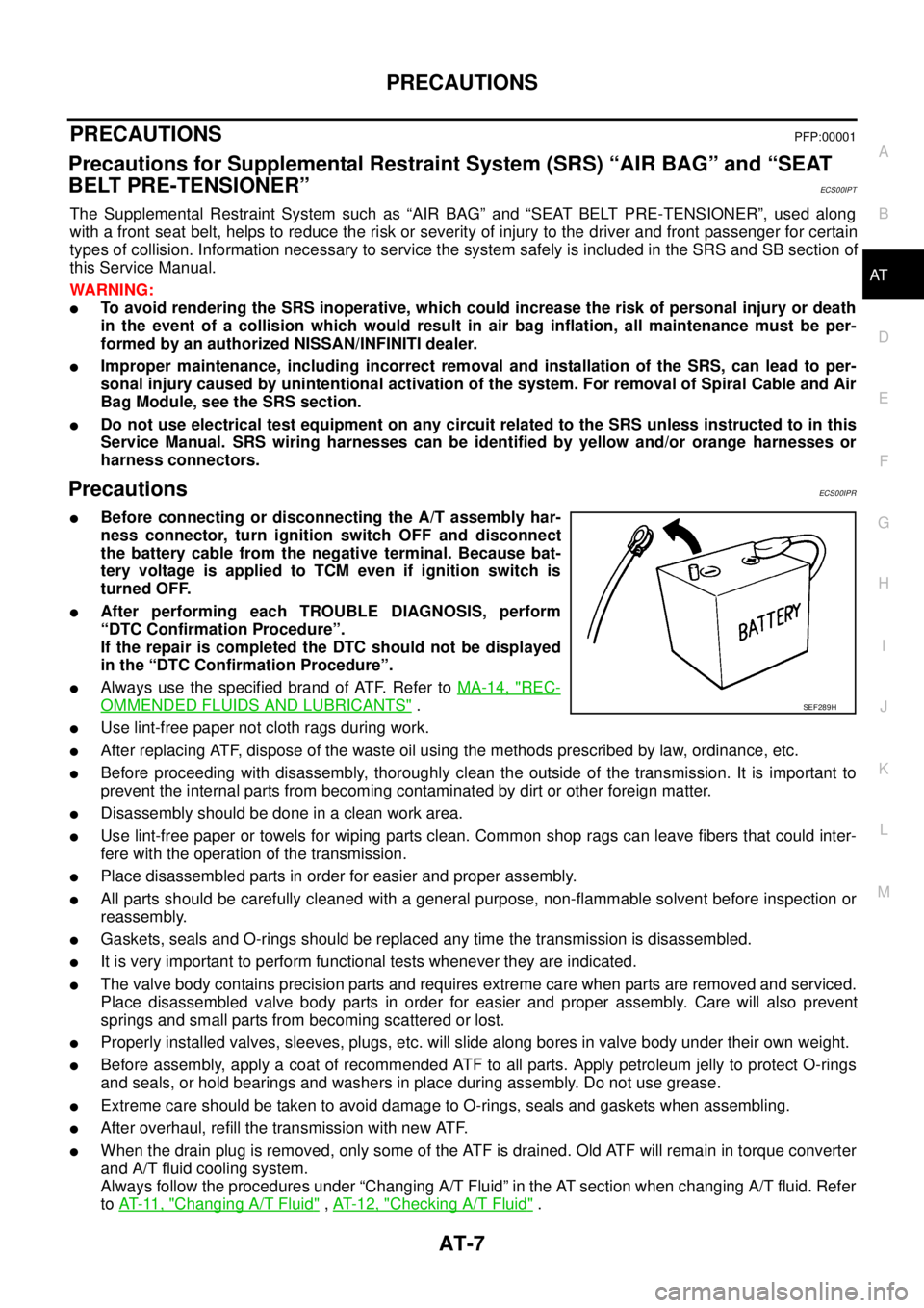
lBefore connecting or disconnecting the A/T assembly har-
ness connector, turn ignition switch OFF and disconnect
the battery cable from the negative terminal. Because bat-
tery voltage is applied to TCM even if ignition switch is
turned OFF.
lAfter performing each TROUBLE DIAGNOSIS, perform
“DTC Confirmation Procedure”.
If the repair is completed the DTC should not be displayed
in the “DTC Confirmation Procedure”.
lAlways use the specified brand of ATF. Refer toMA-14, "REC-
OMMENDED FLUIDS AND LUBRICANTS".
lUse lint-free paper not cloth rags during work.
lAfter replacing ATF, dispose of the waste oil using the methods prescribed by law, ordinance, etc.
lBefore proceeding with disassembly, thoroughly clean the outside of the transmission. It is important to
prevent the internal parts from becoming contaminated by dirt or other foreign matter.
lDisassembly should be done in a clean work area.
lUse lint-free paper or towels for wiping parts clean. Common shop rags can leave fibers that could inter-
fere with the operation of the transmission.
lPlace disassembled parts in order for easier and proper assembly.
lAll parts should be carefully cleaned with a general purpose, non-flammable solvent before inspection or
reassembly.
lGaskets, seals and O-rings should be replaced any time the transmission is disassembled.
lIt is very important to perform functional tests whenever they are indicated.
lThe valve body contains precision parts and requires extreme care when parts are removed and serviced.
Place disassembled valve body parts in order for easier and proper assembly. Care will also prevent
springs and small parts from becoming scattered or lost.
lProperly installed valves, sleeves, plugs, etc. will slide along bores in valve body under their own weight.
lBefore assembly, apply a coat of recommended ATF to all parts. Apply petroleum jelly to protect O-rings
and seals, or hold bearings and washers in place during assembly. Do not use grease.
lExtreme care should be taken to avoid damage to O-rings, seals and gaskets when assembling.
lAfter overhaul, refill the transmission with new ATF.
lWhen the drain plug is removed, only some of the ATF is drained. Old ATF will remain in torque converter
and A/T fluid cooling system.
Always follow the procedures under “Changing A/T Fluid” in the AT section when changing A/T fluid. Refer
toAT-11, "
Changing A/T Fluid",AT-12, "Checking A/T Fluid".
SEF289H
Page 331 of 3171
SERVICE DATA AND SPECIFICATIONS (SDS)
AT-323
D
E
F
G
H
I
J
K
L
MA
B
AT
SERVICE DATA AND SPECIFICATIONS (SDS)PFP:00030
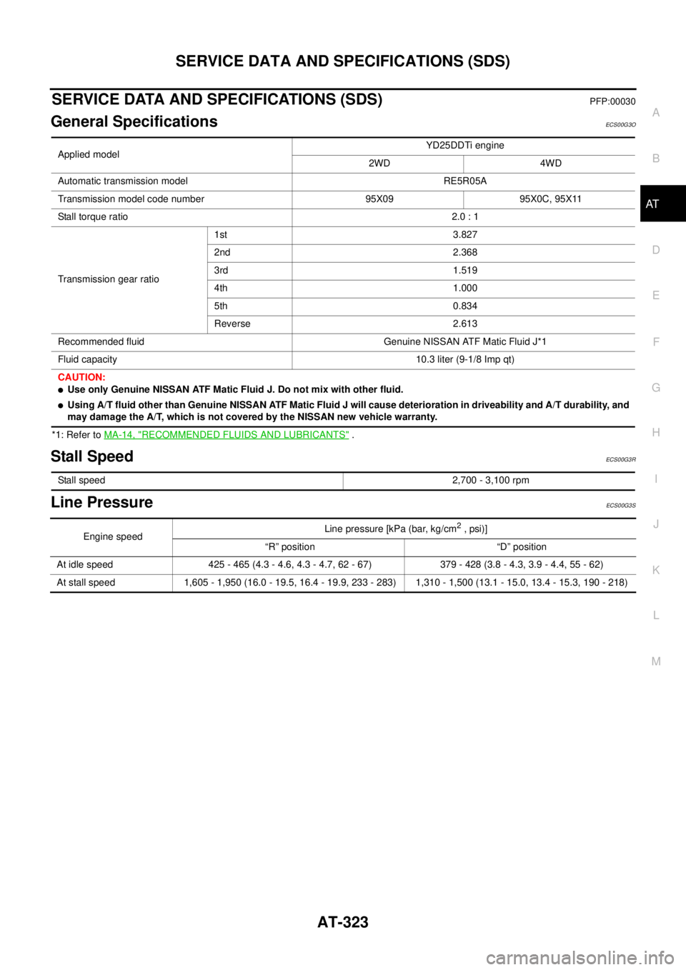
General SpecificationsECS00G3O
*1: Refer toMA-14, "RECOMMENDED FLUIDS AND LUBRICANTS".
Stall SpeedECS00G3R
Line PressureECS00G3S
Applied modelYD25DDTi engine
2WD 4WD
Automatic transmission model RE5R05A
Transmission model code number 95X09 95X0C, 95X11
Stall torque ratio2.0 : 1
Transmission gear ratio1st 3.827
2nd 2.368
3rd 1.519
4th 1.000
5th 0.834
Reverse 2.613
Recommended fluid Genuine NISSAN ATF Matic Fluid J*1
Fluid capacity 10.3 liter (9-1/8 Imp qt)
CAUTION:
lUse only Genuine NISSAN ATF Matic Fluid J. Do not mix with other fluid.
lUsing A/T fluid other than Genuine NISSAN ATF Matic Fluid J will cause deterioration in driveability and A/T durability, and
may damage the A/T, which is not covered by the NISSAN new vehicle warranty.
Stall speed2,700 - 3,100 rpm
Engine speedLine pressure [kPa (bar, kg/cm2,psi)]
“R” position “D” position
At idle speed 425 - 465 (4.3 - 4.6, 4.3 - 4.7, 62 - 67) 379 - 428 (3.8 - 4.3, 3.9 - 4.4, 55 - 62)
At stall speed 1,605 - 1,950 (16.0 - 19.5, 16.4 - 19.9, 233 - 283) 1,310 - 1,500 (13.1 - 15.0, 13.4 - 15.3, 190 - 218)
Page 866 of 3171
CL-2
PRECAUTIONS
PRECAUTIONS
PFP:00001
ServiceNoticeorPrecautionsECS00ICC
lRecommended clutch fluid is brake fluid “DOT 3” or “DOT 4”. Refer toMA-14, "RECOMMENDED FLUIDS
AND LUBRICANTS".
lDo not reuse drained clutch fluid.
lBe careful not to splash clutch fluid on painted areas.
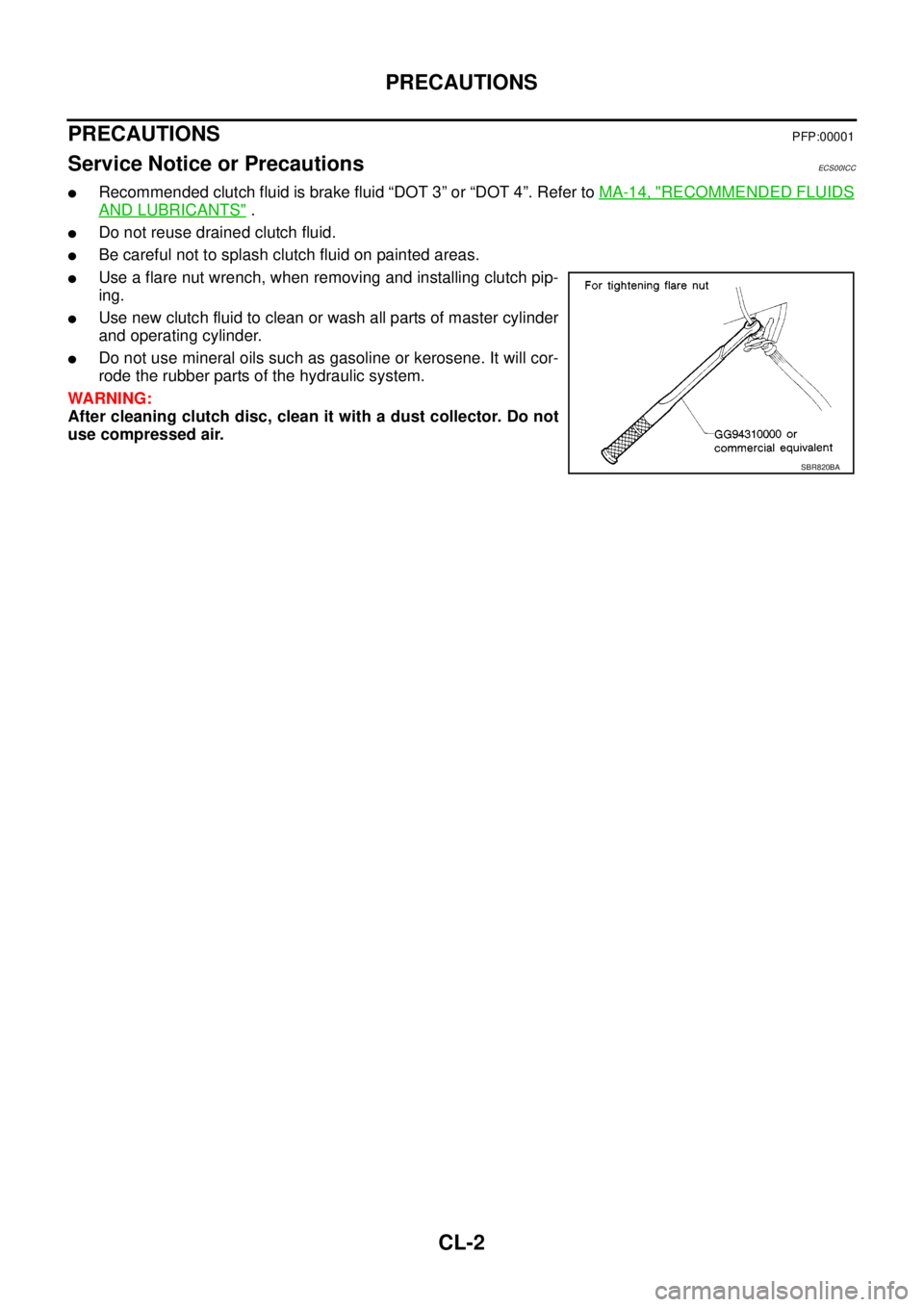
lUse a flare nut wrench, when removing and installing clutch pip-
ing.
lUse new clutch fluid to clean or wash all parts of master cylinder
and operating cylinder.
lDo not use mineral oils such as gasoline or kerosene. It will cor-
rode the rubber parts of the hydraulic system.
WARNING:
After cleaning clutch disc, clean it with a dust collector. Do not
use compressed air.
SBR820BA
Page 1447 of 3171
CAMSHAFT
EM-65
C
D
E
F
G
H
I
J
K
L
MA
EM
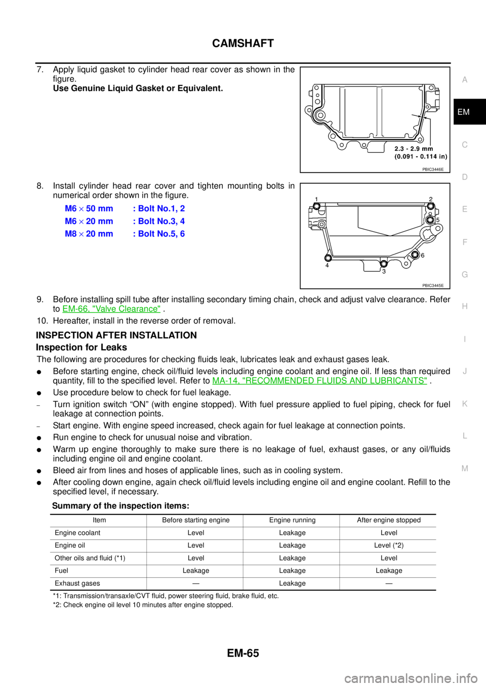
7. Apply liquid gasket to cylinder head rear cover as shown in the
figure.
Use Genuine Liquid Gasket or Equivalent.
8. Install cylinder head rear cover and tighten mounting bolts in
numerical order shown in the figure.
9. Before installing spill tube after installing secondary timing chain, check and adjust valve clearance. Refer
toEM-66, "
Valve Clearance".
10. Hereafter, install in the reverse order of removal.
INSPECTION AFTER INSTALLATION
Inspection for Leaks
The following are procedures for checking fluids leak, lubricates leak and exhaust gases leak.
lBefore starting engine, check oil/fluid levels including engine coolant and engine oil. If less than required
quantity, fill to the specified level. Refer toMA-14, "
RECOMMENDED FLUIDS AND LUBRICANTS".
lUse procedure below to check for fuel leakage.
–Turn ignition switch “ON” (with engine stopped). With fuel pressure applied to fuel piping, check for fuel
leakage at connection points.
–Start engine. With engine speed increased, check again for fuel leakage at connection points.
lRun engine to check for unusual noise and vibration.
lWarm up engine thoroughly to make sure there is no leakage of fuel, exhaust gases, or any oil/fluids
including engine oil and engine coolant.
lBleed air from lines and hoses of applicable lines, such as in cooling system.
lAfter cooling down engine, again check oil/fluid levels including engine oil and engine coolant. Refill to the
specified level, if necessary.
Summary of the inspection items:
*1: Transmission/transaxle/CVT fluid, power steering fluid, brake fluid, etc.
*2: Check engine oil level 10 minutes after engine stopped.
PBIC3446E
M6´50 mm : Bolt No.1, 2
M6´20 mm : Bolt No.3, 4
M8´20 mm : Bolt No.5, 6
PBIC3445E
Item Before starting engine Engine running After engine stopped
Engine coolant Level Leakage Level
Engine oil Level Leakage Level (*2)
Other oils and fluid (*1) Level Leakage Level
Fuel Leakage Leakage Leakage
Exhaust gases — Leakage —
Page 1459 of 3171
SECONDARY TIMING CHAIN
EM-77
C
D
E
F
G
H
I
J
K
L
MA
EM
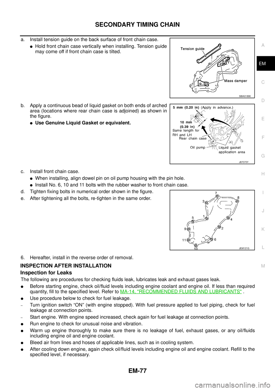
a. Install tension guide on the back surface of front chain case.
lHold front chain case vertically when installing. Tension guide
may come off if front chain case is tilted.
b. Apply a continuous bead of liquid gasket on both ends of arched
area (locations where rear chain case is adjoined) as shown in
the figure.
lUse Genuine Liquid Gasket or equivalent.
c. Install front chain case.
lWhen installing, align dowel pin on oil pump housing with the pin hole.
lInstall No. 6, 10 and 11 bolts with the rubber washer to front chain case.
d. Tighten fixing bolts in numerical order shown in the figure.
e. After tightening all the bolts, re-tighten in the same order.
6. Hereafter, install in the reverse order of removal.
INSPECTION AFTER INSTALLATION
Inspection for Leaks
The following are procedures for checking fluids leak, lubricates leak and exhaust gases leak.
lBefore starting engine, check oil/fluid levels including engine coolant and engine oil. If less than required
quantity, fill to the specified level. Refer toMA-14, "
RECOMMENDED FLUIDS AND LUBRICANTS".
lUse procedure below to check for fuel leakage.
–Turn ignition switch “ON” (with engine stopped). With fuel pressure applied to fuel piping, check for fuel
leakage at connection points.
–Start engine. With engine speed increased, check again for fuel leakage at connection points.
lRun engine to check for unusual noise and vibration.
lWarm up engine thoroughly to make sure there is no leakage of fuel, exhaust gases, or any oil/fluids
including engine oil and engine coolant.
lBleed air from lines and hoses of applicable lines, such as in cooling system.
lAfter cooling down engine, again check oil/fluid levels including engine oil and engine coolant. Refill to the
specified level, if necessary.
SBIA0189E
JEF370Y
JEM121G
Page 1473 of 3171
PRIMARY TIMING CHAIN
EM-91
C
D
E
F
G
H
I
J
K
L
MA
EM
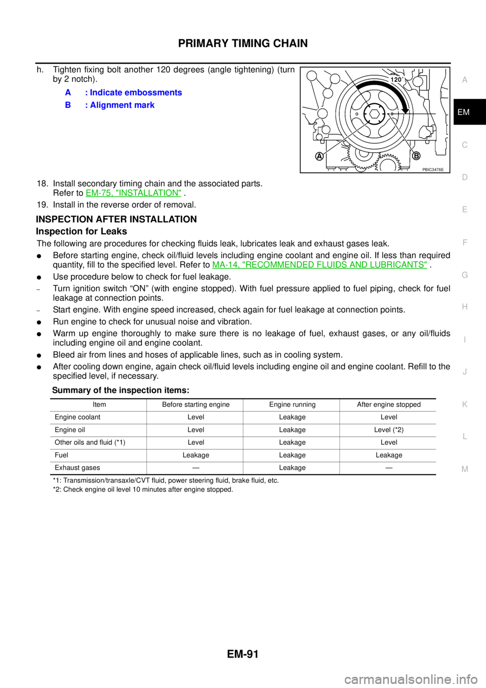
h. Tighten fixing bolt another 120 degrees (angle tightening) (turn
by 2 notch).
18. Install secondary timing chain and the associated parts.
Refer toEM-75, "
INSTALLATION".
19. Install in the reverse order of removal.
INSPECTION AFTER INSTALLATION
Inspection for Leaks
The following are procedures for checking fluids leak, lubricates leak and exhaust gases leak.
lBefore starting engine, check oil/fluid levels including engine coolant and engine oil. If less than required
quantity, fill to the specified level. Refer toMA-14, "
RECOMMENDED FLUIDS AND LUBRICANTS".
lUse procedure below to check for fuel leakage.
–Turn ignition switch “ON” (with engine stopped). With fuel pressure applied to fuel piping, check for fuel
leakage at connection points.
–Start engine. With engine speed increased, check again for fuel leakage at connection points.
lRun engine to check for unusual noise and vibration.
lWarm up engine thoroughly to make sure there is no leakage of fuel, exhaust gases, or any oil/fluids
including engine oil and engine coolant.
lBleed air from lines and hoses of applicable lines, such as in cooling system.
lAfter cooling down engine, again check oil/fluid levels including engine oil and engine coolant. Refill to the
specified level, if necessary.
Summary of the inspection items:
*1: Transmission/transaxle/CVT fluid, power steering fluid, brake fluid, etc.
*2: Check engine oil level 10 minutes after engine stopped.
A : Indicate embossments
B : Alignment mark
PBIC3476E
Item Before starting engine Engine running After engine stopped
Engine coolant Level Leakage Level
Engine oil Level Leakage Level (*2)
Other oils and fluid (*1) Level Leakage Level
Fuel Leakage Leakage Leakage
Exhaust gases — Leakage —
Page 1480 of 3171
EM-98
CYLINDER HEAD
lBefore installing, remove carbon depositing on mounting hole of glow plug with a reamer.
6. Install engine coolant temperature sensor.
7. Install in the reverse order of removal.
INSPECTION AFTER INSTALLATION
Inspection for Leaks
The following are procedures for checking fluids leak, lubricates leak and exhaust gases leak.
lBefore starting engine, check oil/fluid levels including engine coolant and engine oil. If less than required
quantity, fill to the specified level. Refer toMA-14, "
RECOMMENDED FLUIDS AND LUBRICANTS".
lUse procedure below to check for fuel leakage.
–Turn ignition switch “ON” (with engine stopped). With fuel pressure applied to fuel piping, check for fuel
leakage at connection points.
–Start engine. With engine speed increased, check again for fuel leakage at connection points.
lRun engine to check for unusual noise and vibration.
lWarm up engine thoroughly to make sure there is no leakage of fuel, exhaust gases, or any oil/fluids
including engine oil and engine coolant.
lBleed air from lines and hoses of applicable lines, such as in cooling system.
lAfter cooling down engine, again check oil/fluid levels including engine oil and engine coolant. Refill to the
specified level, if necessary.
Summary of the inspection items:
*1: Transmission/transaxle/CVT fluid, power steering fluid, brake fluid, etc.
*2: Check engine oil level 10 minutes after engine stopped.Item Before starting engine Engine running After engine stopped
Engine coolant Level Leakage Level
Engine oil Level Leakage Level (*2)
Other oils and fluid (*1) Level Leakage Level
Fuel Leakage Leakage Leakage
Exhaust gases — Leakage —
Page 1490 of 3171
EM-108
ENGINE ASSEMBLY
Removal
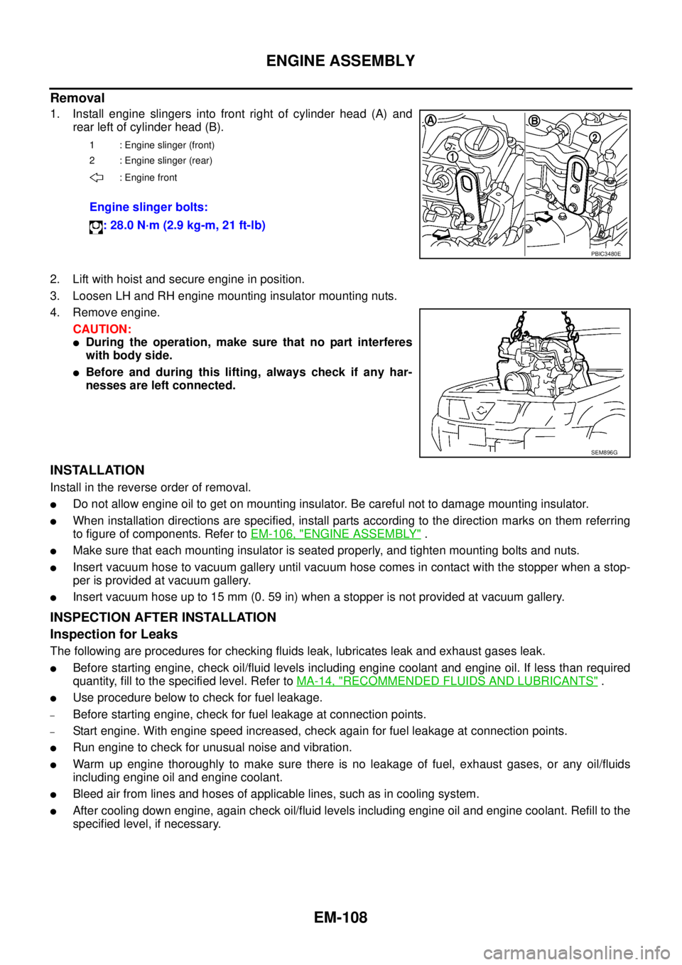
1. Install engine slingers into front right of cylinder head (A) and
rear left of cylinder head (B).
2. Lift with hoist and secure engine in position.
3. Loosen LH and RH engine mounting insulator mounting nuts.
4. Remove engine.
CAUTION:
lDuring the operation, make sure that no part interferes
with body side.
lBefore and during this lifting, always check if any har-
nesses are left connected.
INSTALLATION
Install in the reverse order of removal.
lDo not allow engine oil to get on mounting insulator. Be careful not to damage mounting insulator.
lWhen installation directions are specified, install parts according to the direction marks on them referring
to figure of components. Refer toEM-106, "
ENGINE ASSEMBLY".
lMake sure that each mounting insulator is seated properly, and tighten mounting bolts and nuts.
lInsert vacuum hose to vacuum gallery until vacuum hose comes in contact with the stopper when a stop-
per is provided at vacuum gallery.
lInsert vacuum hose up to 15 mm (0. 59 in) when a stopper is not provided at vacuum gallery.
INSPECTION AFTER INSTALLATION
Inspection for Leaks
The following are procedures for checking fluids leak, lubricates leak and exhaust gases leak.
lBefore starting engine, check oil/fluid levels including engine coolant and engine oil. If less than required
quantity, fill to the specified level. Refer toMA-14, "
RECOMMENDED FLUIDS AND LUBRICANTS".
lUse procedure below to check for fuel leakage.
–Before starting engine, check for fuel leakage at connection points.
–Start engine. With engine speed increased, check again for fuel leakage at connection points.
lRun engine to check for unusual noise and vibration.
lWarm up engine thoroughly to make sure there is no leakage of fuel, exhaust gases, or any oil/fluids
including engine oil and engine coolant.
lBleed air from lines and hoses of applicable lines, such as in cooling system.
lAfter cooling down engine, again check oil/fluid levels including engine oil and engine coolant. Refill to the
specified level, if necessary.
1 : Engine slinger (front)
2 : Engine slinger (rear)
: Engine front
Engine slinger bolts:
: 28.0 N·m (2.9 kg-m, 21 ft-lb)
PBIC3480E
SEM896G