Page 996 of 3171
EC-16
ENGINE CONTROL SYSTEM
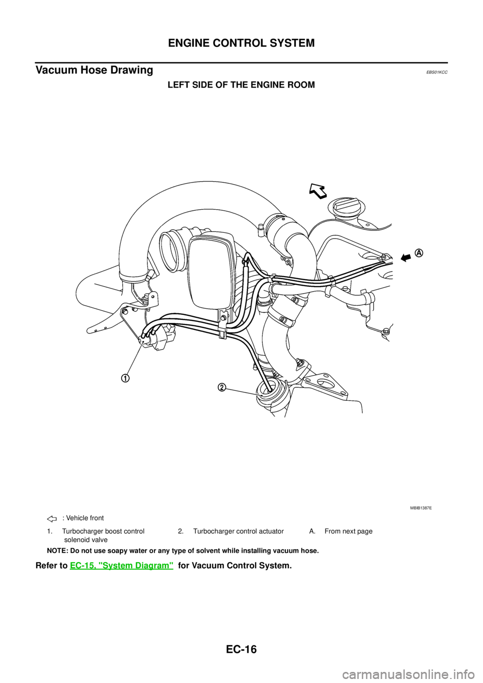
Vacuum Hose Drawing
EBS01KCC
LEFT SIDE OF THE ENGINE ROOM
Refer toEC-15, "System Diagram"for Vacuum Control System.
MBIB1387E
: Vehicle front
1. Turbocharger boost control
solenoid valve2. Turbocharger control actuator A. From next page
NOTE: Do not use soapy water or any type of solvent while installing vacuum hose.
Page 998 of 3171
EC-18
ENGINE CONTROL SYSTEM
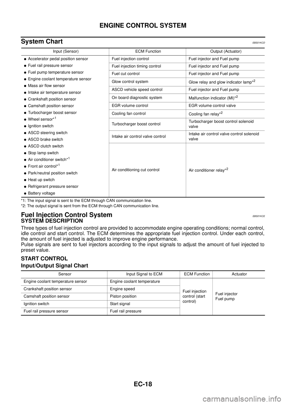
System Chart
EBS01KCD
*1: The input signal is sent to the ECM through CAN communication line.
*2: The output signal is sent from the ECM through CAN communication line.
Fuel Injection Control SystemEBS01KCE
SYSTEM DESCRIPTION
Three types of fuel injection control are provided to accommodate engine operating conditions; normal control,
idle control and start control. The ECM determines the appropriate fuel injection control. Under each control,
the amount of fuel injected is adjusted to improve engine performance.
Pulse signals are sent to fuel injectors according to the input signals to adjust the amount of fuel injected to
preset value.
START CONTROL
Input/Output Signal Chart
Input (Sensor) ECM Function Output (Actuator)
lAccelerator pedal position sensor
lFuel rail pressure sensor
lFuel pump temperature sensor
lEngine coolant temperature sensor
lMass air flow sensor
lIntake air temperature sensor
lCrankshaft position sensor
lCamshaft position sensor
lTurbocharger boost sensor
lWheel sensor*1
lIgnition switch
lASCD steering switch
lASCD brake switch
lASCD clutch switch
lSt o p l a m p s w it c h
lAir conditioner switch*1
lFront air control*1
lPark/neutral position switch
lHeat up switch
lRefrigerant pressure sensor
lBattery voltageFuel injection control Fuel injector and Fuel pump
Fuel injection timing control Fuel injector and Fuel pump
Fuel cut control Fuel injector and Fuel pump
Glow control system
Glow relay and glow indicator lamp*
2
ASCD vehicle speed control Fuel injector and Fuel pump
On board diagnostic system
Malfunction indicator (MI)*
2
EGR volume control EGR volume control valve
Cooling fan control
Cooling fan relay*
2
Turbocharger boost controlTurbocharger boost control solenoid
valve
Intake air control valve controlIntake air control valve control solenoid
valve
Air conditioning cut control
Air conditioner relay*
2
Sensor Input Signal to ECM ECM Function Actuator
Engine coolant temperature sensor Engine coolant temperature
Fuel injection
control (start
control)Fuel injector
Fuel pump Crankshaft position sensor Engine speed
Camshaft position sensor Piston position
Ignition switch Start signal
Fuel rail pressure sensor Fuel rail pressure
Page 1026 of 3171
EC-46
TROUBLE DIAGNOSIS
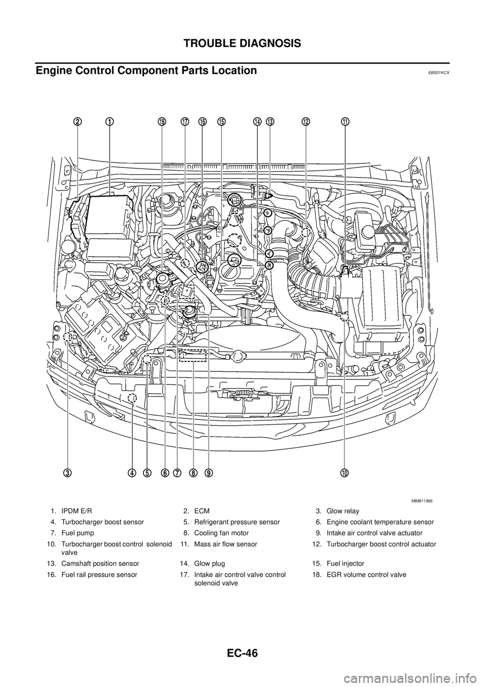
Engine Control Component Parts Location
EBS01KCX
1. IPDM E/R 2. ECM 3. Glow relay
4. Turbocharger boost sensor 5. Refrigerant pressure sensor 6. Engine coolant temperature sensor
7. Fuel pump 8. Cooling fan motor 9. Intake air control valve actuator
10. Turbocharger boost control solenoid
valve11. Mass air flow sensor 12. Turbocharger boost control actuator
13. Camshaft position sensor 14. Glow plug 15. Fuel injector
16. Fuel rail pressure sensor 17. Intake air control valve control
solenoid valve18. EGR volume control valve
MBIB1198E
Page 1029 of 3171
TROUBLE DIAGNOSIS
EC-49
C
D
E
F
G
H
I
J
K
L
MA
EC
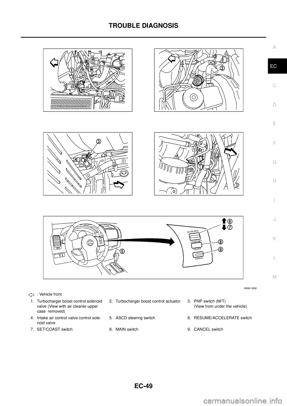
: Vehicle front
1. Turbocharger boost control solenoid
valve (View with air cleaner upper
case removed)2. Turbocharger boost control actuator 3. PNP switch (M/T)
(View from under the vehicle)
4. Intake air control valve control sole-
noid valve5. ASCD steering switch 6. RESUME/ACCELERATE switch
7. SET/COAST switch 8. MAIN switch 9. CANCEL switch
MBIB1289E
Page 1127 of 3171
DTC P0234 TC SYSTEM
EC-147
C
D
E
F
G
H
I
J
K
L
MA
EC
DTCP0234TCSYSTEMPFP:14411
DescriptionEBS01KG1
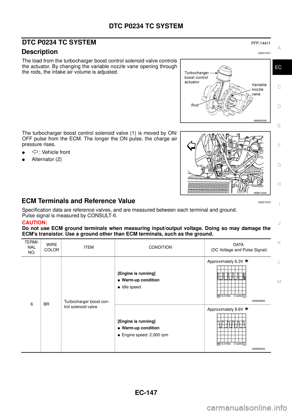
The load from the turbocharger boost control solenoid valve controls
the actuator. By changing the variable nozzle vane opening through
the rods, the intake air volume is adjusted.
The turbocharger boost control solenoid valve (1) is moved by ON/
OFF pulse from the ECM. The longer the ON pulse, the charge air
pressure rises.
l: Vehicle front
lAlternator (2)
ECM Terminals and Reference ValueEBS01KG3
Specification data are reference valves, and are measured between each terminal and ground.
Pulse signal is measured by CONSULT-II.
CAUTION:
Do not use ECM ground terminals when measuring input/output voltage. Doing so may damage the
ECM's transistor. Use a ground other than ECM terminals, such as the ground.
MBIB0626E
MBIB1206E
TERMI-
NAL
NO.WIRE
COLORITEM CONDITIONDATA
(DC Voltage and Pulse Signal)
6BRTurbocharger boost con-
trol solenoid valve[Engine is running]
lWarm-up condition
lIdle speedApproximately 6.3V
[Engine is running]
lWarm-up condition
lEngine speed: 2,000 rpmApproximately 8.6V
MBIB0889E
MBIB0890E
Page 1128 of 3171
EC-148
DTC P0234 TC SYSTEM
: Average voltage for pulse signal (Actual pulse signal can be confirmed by oscilloscope.)
On Board Diagnosis LogicEBS01KG4
The MI will not light up for this self-diagnosis.
NOTE:
If DTC P0234 is displayed with DTC P0652 or P0653, first perform the trouble diagnosis for DTC P0652
or P0653. Refer toEC-227, "
DTC P0652, P0653 SENSOR POWER SUPPLY".
Overall Function CheckEBS01KG5
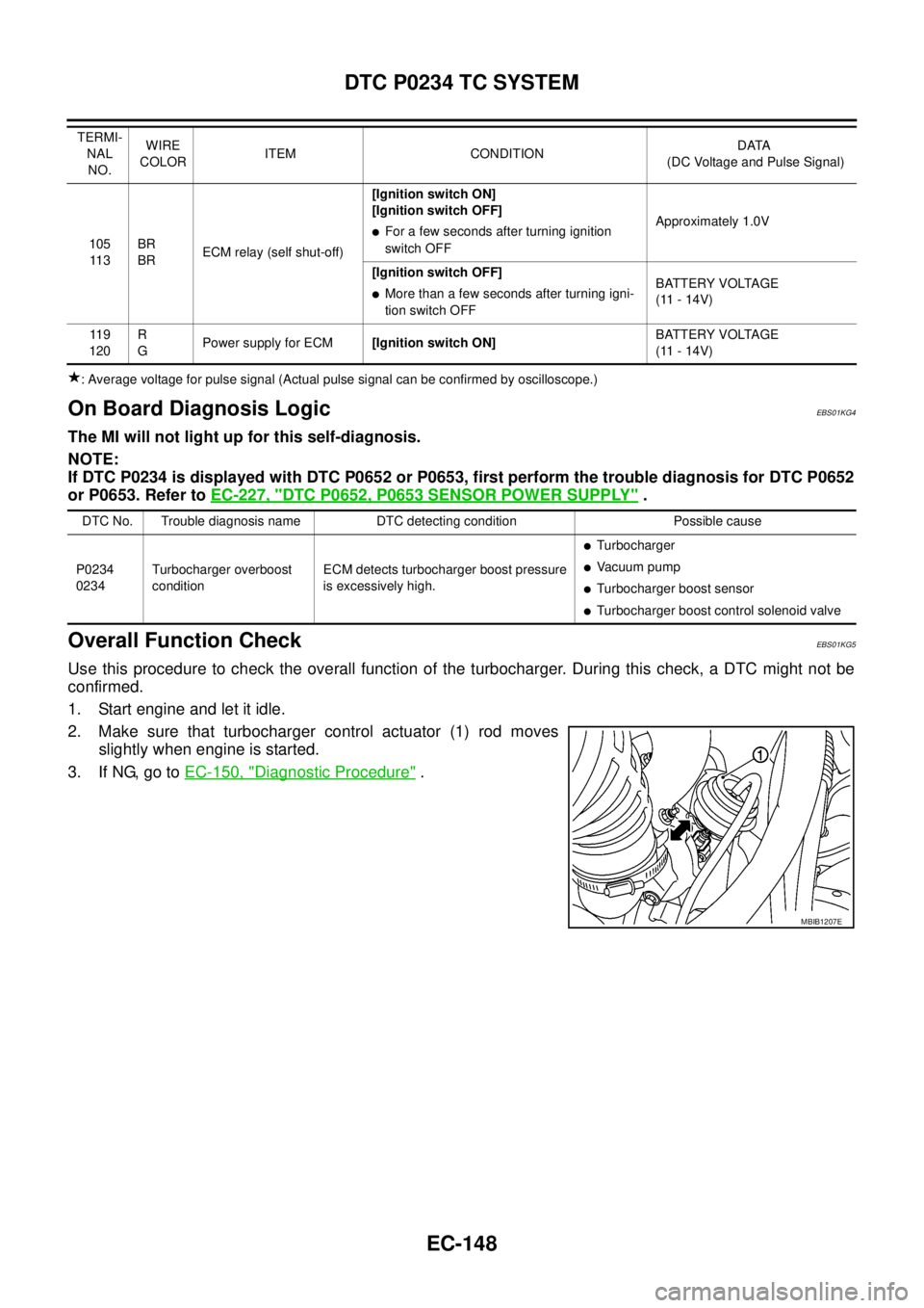
Use this procedure to check the overall function of the turbocharger. During this check, a DTC might not be
confirmed.
1. Start engine and let it idle.
2. Make sure that turbocharger control actuator (1) rod moves
slightly when engine is started.
3. If NG, go toEC-150, "
Diagnostic Procedure".
105
11 3BR
BRECM relay (self shut-off)[Ignition switch ON]
[Ignition switch OFF]lFor a few seconds after turning ignition
switch OFFApproximately 1.0V
[Ignition switch OFF]
lMore than a few seconds after turning igni-
tion switch OFFBATTERY VOLTAGE
(11 - 14V)
11 9
120R
GPower supply for ECM[Ignition switch ON]BATTERY VOLTAGE
(11 - 14V) TERMI-
NAL
NO.WIRE
COLORITEM CONDITIONDATA
(DC Voltage and Pulse Signal)
DTC No. Trouble diagnosis name DTC detecting condition Possible cause
P0234
0234Turbocharger overboost
conditionECM detects turbocharger boost pressure
is excessively high.
lTurbocharger
lVa c u u m p u m p
lTurbocharger boost sensor
lTurbocharger boost control solenoid valve
MBIB1207E
Page 1130 of 3171
EC-150
DTC P0234 TC SYSTEM
Diagnostic Procedure
EBS01KG7
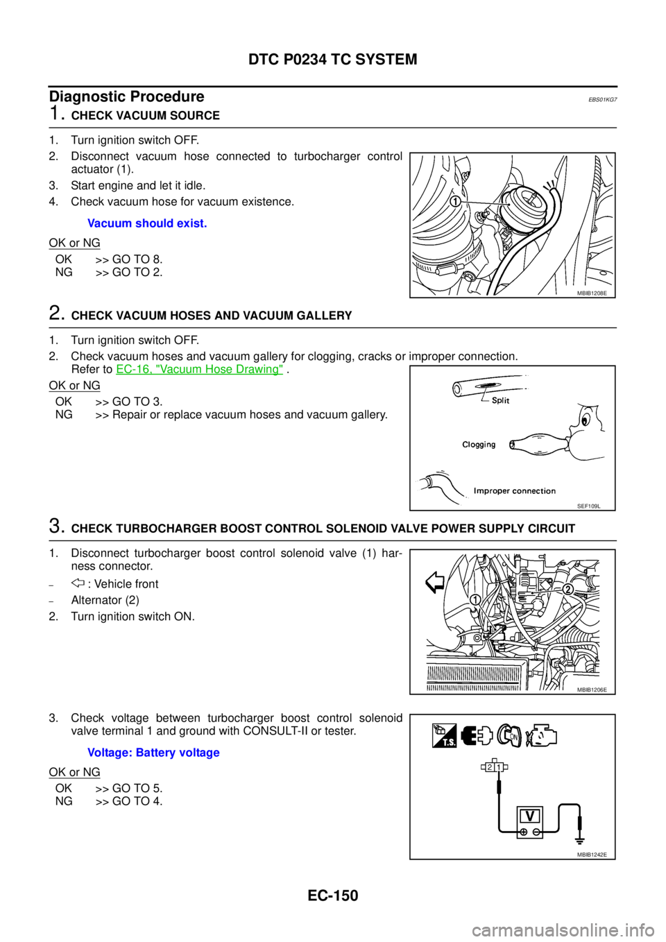
1.CHECK VACUUM SOURCE
1. Turn ignition switch OFF.
2. Disconnect vacuum hose connected to turbocharger control
actuator (1).
3. Start engine and let it idle.
4. Check vacuum hose for vacuum existence.
OK or NG
OK >> GO TO 8.
NG >> GO TO 2.
2.CHECK VACUUM HOSES AND VACUUM GALLERY
1. Turn ignition switch OFF.
2. Check vacuum hoses and vacuum gallery for clogging, cracks or improper connection.
Refer toEC-16, "
Vacuum Hose Drawing".
OK or NG
OK >> GO TO 3.
NG >> Repair or replace vacuum hoses and vacuum gallery.
3.CHECK TURBOCHARGER BOOST CONTROL SOLENOID VALVE POWER SUPPLY CIRCUIT
1. Disconnect turbocharger boost control solenoid valve (1) har-
ness connector.
–: Vehicle front
–Alternator (2)
2. Turn ignition switch ON.
3. Check voltage between turbocharger boost control solenoid
valve terminal 1 and ground with CONSULT-II or tester.
OK or NG
OK >> GO TO 5.
NG >> GO TO 4.Vacuum should exist.
MBIB1208E
SEF109L
MBIB1206E
Voltage: Battery voltage
MBIB1242E
Page 1131 of 3171
DTC P0234 TC SYSTEM
EC-151
C
D
E
F
G
H
I
J
K
L
MA
EC
4.DETECT MALFUNCTIONING PART
Check the following.
lHarness connectors E9, F4
lHarness for open or short between IPDM E/R and turbocharger boost control solenoid valve
lHarness for open or short between ECM and turbocharger boost control solenoid valve
>> Repair open circuit or short to ground or short to power in harness or connectors.
5.CHECK TURBOCHARGER BOOST CONTROL SOLENOID VALVE OUTPUT SIGNAL CIRCUIT FOR
OPEN AND SHORT
1. Turn ignition switch OFF.
2. Disconnect ECM harness connector.
3. Check harness continuity between ECM terminals 6 and turbocharger boost control solenoid valve termi-
nal 2.
Refer to Wiring Diagram.
4. Also check harness for short to ground and short to power.
OK or NG
OK >> GO TO 6.
NG >> Repair open circuit or short to ground or short to power in harness or connectors.
6.CHECK TURBOCHARGE BOOST CONTROL SOLENOID VALVE
Refer toEC-152, "
Component Inspection".
OK or NG
OK >> GO TO 7.
NG >> Replace turbocharger boost control solenoid valve.
7.CHECK VACUUM PUMP
Refer toEM-42, "
VACUUM PUMP".
OK or NG
OK >> GO TO 8.
NG >> Replace vacuum pump assembly.
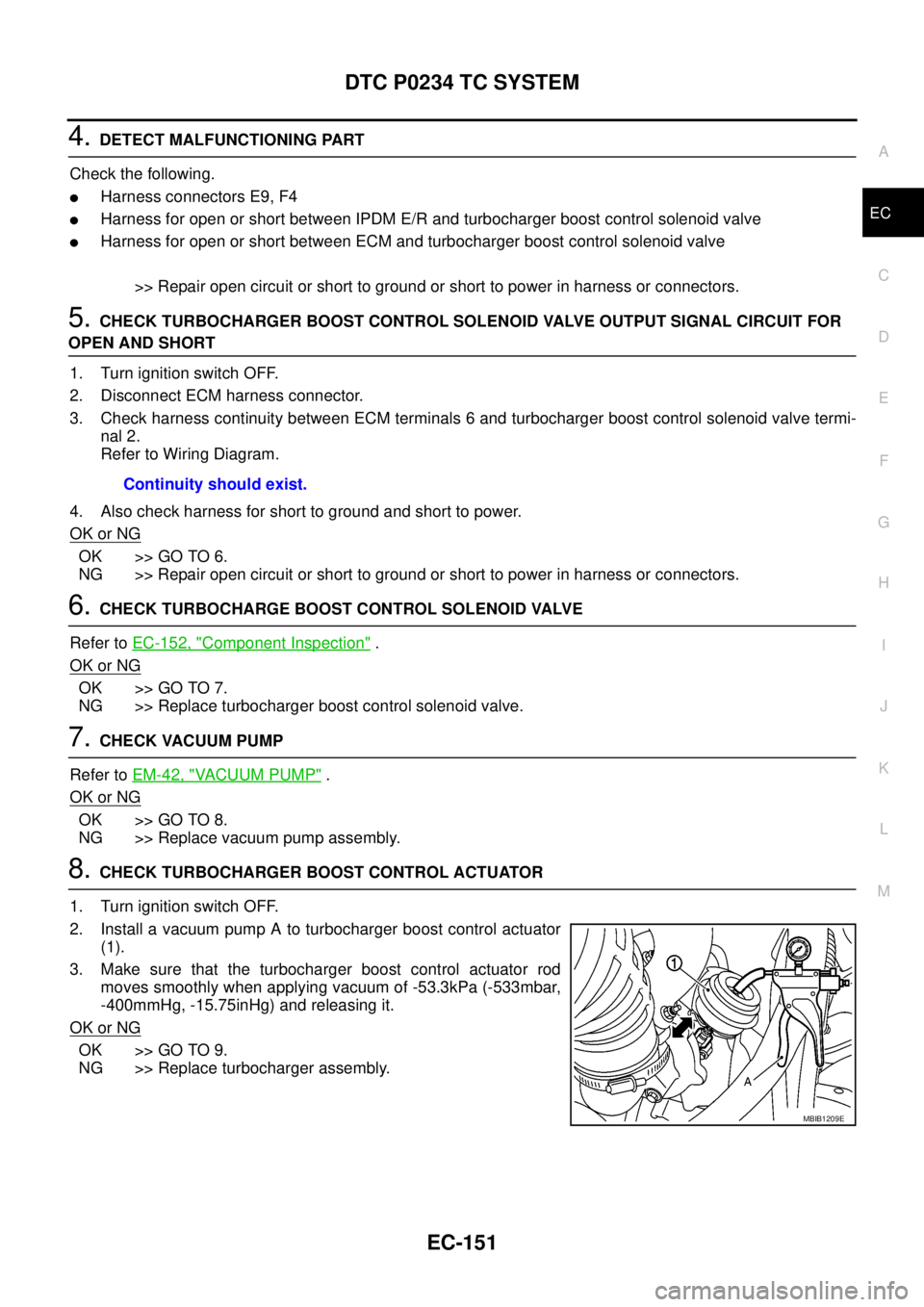
8.CHECK TURBOCHARGER BOOST CONTROL ACTUATOR
1. Turn ignition switch OFF.
2. Install a vacuum pump A to turbocharger boost control actuator
(1).
3. Make sure that the turbocharger boost control actuator rod
moves smoothly when applying vacuum of -53.3kPa (-533mbar,
-400mmHg, -15.75inHg) and releasing it.
OK or NG
OK >> GO TO 9.
NG >> Replace turbocharger assembly.Continuity should exist.
MBIB1209E