2005 NISSAN NAVARA wheel
[x] Cancel search: wheelPage 551 of 3171

TROUBLE DIAGNOSIS
AV-63
C
D
E
F
G
H
I
J
L
MA
B
AV
Steering Wheel SwitchEKS00Q6R
Without NAVI
With NAVI
Component Parts InspectionEKS00Q6S
STEERING WHEEL SWITCH UNIT INSPECTION
lCheck continuity between combination switch harness connector M302 terminal 15 and terminal 16.
lCheck continuity between combination switch harness connector M302 terminal 14 and terminal 16.
Symptoms Probable malfunction location
All steering wheel switches are not operated
lRemote control signal ground circuit
lSteering wheel switch
lAudio unit
Only specified switch cannot be operated Steering wheel switch
“MODE”, “SEEK UP”, and “VOL UP” switches are not oper-
ated
lRemote control signal A circuit
lSteering wheel switch
lAudio unit
“SEEK DOWN”, and “VOL DOWN” switches are not oper-
ated
lRemote control signal B circuit
lSteering wheel switch
lAudio unit
Symptoms Probable malfunction location
All steering wheel switches are not operated
lRemote control signal ground circuit
lSteering wheel switch
lAudio unit
Only specified switch cannot be operated Steering wheel switch
“ENTER”, “MENU UP”, “MENU DOWN”, and “SOURCE”
switches are not operated
lRemote control signal A circuit
lSteering wheel switch
lAudio unit
“BACK”, “TEL /PPT”, “VOL UP”, and “VOL DOWN” switches
are not operated
lRemote control signal B circuit
lSteering wheel switch
lAudio unit
Page 558 of 3171
AV-70
TROUBLE DIAGNOSIS
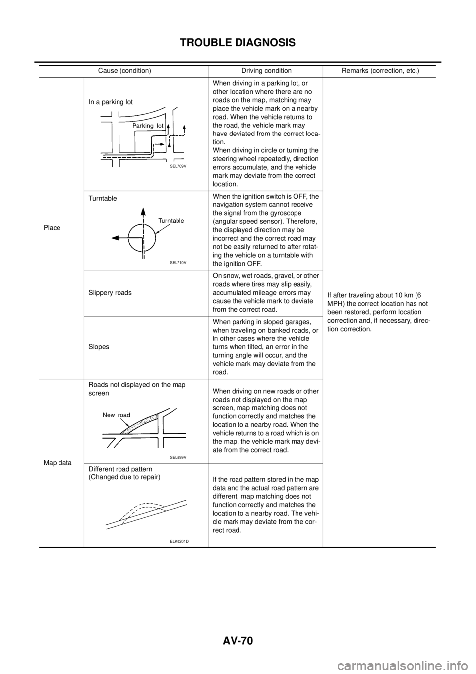
PlaceIn a parking lotWhen driving in a parking lot, or
other location where there are no
roads on the map, matching may
place the vehicle mark on a nearby
road. When the vehicle returns to
the road, the vehicle mark may
have deviated from the correct loca-
tion.
When driving in circle or turning the
steering wheel repeatedly, direction
errors accumulate, and the vehicle
mark may deviate from the correct
location.
If after traveling about 10 km (6
MPH) the correct location has not
been restored, perform location
correction and, if necessary, direc-
tion correction. TurntableWhentheignitionswitchisOFF,the
navigation system cannot receive
the signal from the gyroscope
(angular speed sensor). Therefore,
the displayed direction may be
incorrect and the correct road may
not be easily returned to after rotat-
ing the vehicle on a turntable with
the ignition OFF.
Slippery roadsOn snow, wet roads, gravel, or other
roads where tires may slip easily,
accumulated mileage errors may
cause the vehicle mark to deviate
from the correct road.
SlopesWhen parking in sloped garages,
when traveling on banked roads, or
in other cases where the vehicle
turns when tilted, an error in the
turning angle will occur, and the
vehicle mark may deviate from the
road.
Map dataRoads not displayed on the map
screenWhen driving on new roads or other
roads not displayed on the map
screen, map matching does not
function correctly and matches the
location to a nearby road. When the
vehicle returns to a road which is on
the map, the vehicle mark may devi-
ate from the correct road.
Different road pattern
(Changed due to repair)
If the road pattern stored in the map
data and the actual road pattern are
different, map matching does not
function correctly and matches the
location to a nearby road. The vehi-
cle mark may deviate from the cor-
rect road. Cause (condition) Driving condition Remarks (correction, etc.)
SEL709V
SEL710V
SEL699V
ELK0201D
Page 559 of 3171
TROUBLE DIAGNOSIS
AV-71
C
D
E
F
G
H
I
J
L
MA
B
AV
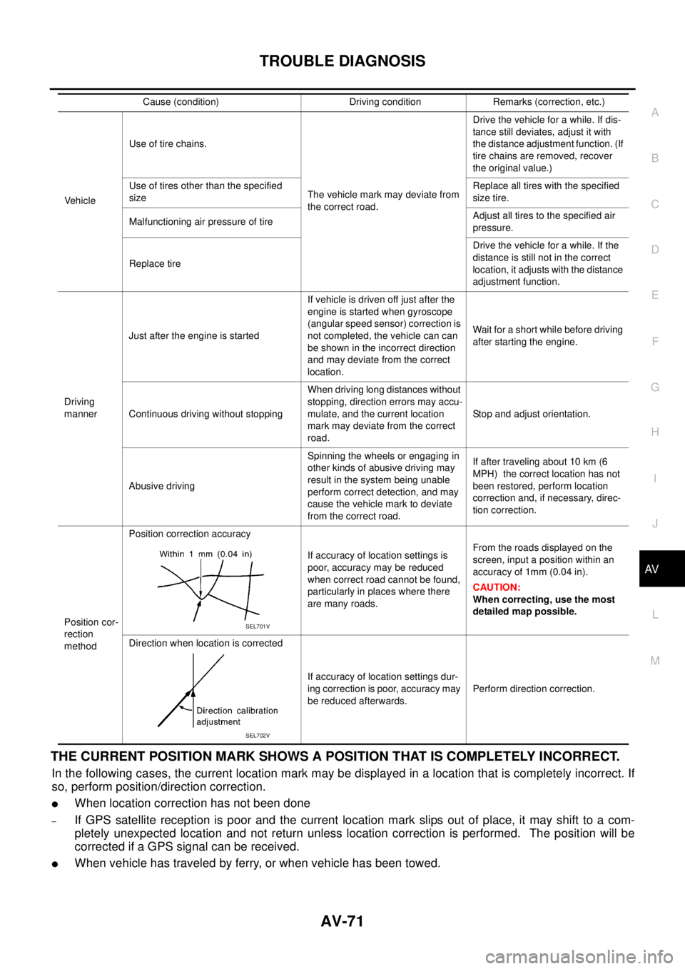
THE CURRENT POSITION MARK SHOWS A POSITION THAT IS COMPLETELY INCORRECT.
In the following cases, the current location mark may be displayed in a location that is completely incorrect. If
so, perform position/direction correction.
lWhen location correction has not been done
–If GPS satellite reception is poor and the current location mark slips out of place, it may shift to a com-
pletely unexpected location and not return unless location correction is performed. The position will be
corrected if a GPS signal can be received.
lWhen vehicle has traveled by ferry, or when vehicle has been towed.
VehicleUse of tire chains.
The vehicle mark may deviate from
the correct road.Drivethevehicleforawhile.Ifdis-
tance still deviates, adjust it with
the distance adjustment function. (If
tire chains are removed, recover
the original value.)
Use of tires other than the specified
sizeReplace all tires with the specified
size tire.
Malfunctioning air pressure of tireAdjust all tires to the specified air
pressure.
Replace tireDrive the vehicle for a while. If the
distance is still not in the correct
location, it adjusts with the distance
adjustment function.
Driving
mannerJust after the engine is startedIf vehicle is driven off just after the
engine is started when gyroscope
(angular speed sensor) correction is
not completed, the vehicle can can
be shown in the incorrect direction
and may deviate from the correct
location.Wait for a short while before driving
after starting the engine.
Continuous driving without stoppingWhen driving long distances without
stopping, direction errors may accu-
mulate, and the current location
mark may deviate from the correct
road.Stop and adjust orientation.
Abusive drivingSpinning the wheels or engaging in
other kinds of abusive driving may
result in the system being unable
perform correct detection, and may
cause the vehicle mark to deviate
from the correct road.If after traveling about 10 km (6
MPH) the correct location has not
been restored, perform location
correction and, if necessary, direc-
tion correction.
Position cor-
rection
methodPosition correction accuracy
If accuracy of location settings is
poor, accuracy may be reduced
when correct road cannot be found,
particularly in places where there
are many roads.From the roads displayed on the
screen, input a position within an
accuracy of 1mm (0.04 in).
CAUTION:
When correcting, use the most
detailed map possible.
Direction when location is corrected
If accuracy of location settings dur-
ing correction is poor, accuracy may
be reduced afterwards.Perform direction correction. Cause (condition) Driving condition Remarks (correction, etc.)
SEL701V
SEL702V
Page 560 of 3171

AV-72
TROUBLE DIAGNOSIS
–Because calculation of the current location cannot be done when traveling with the ignition OFF, for exam-
ple when traveling by ferry or when being towed, the location before travel is displayed. If the precise loca-
tioncanbedetectedwithGPS,thelocationwillbecorrected.
THE CURRENT POSITION MARK JUMPS.
In the following cases, the current location mark may appear to jump as a result of automatic correction of the
current location.
lWhen map matching has been done
–If current location and the current location mark are different when map matching is done, the current
location mark may seem to jump. At this time, the location may be “corrected” to the incorrect road or to a
location which is not on a road.
lWhen GPS location correction has been done
–If current location and the current location mark are different when location is corrected using GPS mea-
surements, the current location mark may seem to jump. At this time, the location may be “corrected” to a
location which is not on a road.
THE CURRENT LOCATION MARK IS IN A RIVER OR THE SEA.
The navigation system moves the current location mark with no distinction between land and rivers or sea. If
the location mark is somehow out of place, it may appear that the vehicle is driving in a river or the sea.
CURRENT LOCATION MARK ROTATES WITHOUT OPERATION
If the ignition switch is turned ON with the turntable rotating, the rotating condition is recorded as the stop con-
dition. Therefore, the current location mark might rotate when actually stopping.
WHEN DRIVING ON THE SAME ROAD, SOMETIMES THE CURRENT LOCATION MARK IS IN
THE CORRECT PLACE AND SOMETIMES IT IS IN THE INCORRECT PLACE.
The conditions of the GPS antenna (GPS data) and gyroscope (angular speed sensor) change gradually.
Depending on the road traveled and operation of the steering wheel, the location detection results will be dif-
ferent. Therefore, even on a road on which the location has never been incorrect, conditions may cause the
vehicle mark to deviate.
LOCATION CORRECTION BY MAP MATCHING IS SLOW.
lThe map matching function needs to refer to the data of the surrounding area. It is necessary to drive
some distance for the function to work.
lBecause of the way map matching operates, when there are many roads running in similar directions in
the surrounding area a matching determination may be impossible. The location will remain uncorrected
until some special feature is found.
ALTHOUGH THE GPS RECEIVING DISPLAY IS GREEN, THE VEHICLE MARK DOES NOT
RETURN TO THE CORRECT LOCATION.
lGPS accuracy has a malfunction range of about 10 m. In some cases the current location mark may not
be on the correct street, even when GPS location correction is done.
lThe navigation system compares the results of GPS location detection with the results from map-match-
ing location detection. The one that is determined to have higher accuracy is used.
lPosition correction by GPS is not available while the vehicle is stopped.
THE NAME OF THE CURRENT PLACE IS NOT DISPLAYED.
The current place name might not be displayed when there is no name of place information in the map screen.
THE DISPLAY IS DIFFERENT BETWEEN BIRDVIEW®AND (FLAT) MAP DISPLAY.
The following is different at birdview®.
lThe current place name displays names that are primarily in the direction of vehicle travel.
lThe amount of time before the vehicle travel or turn angle is updated on the screen is longer than for the
(flat) map display.
lThe conditions for display of place names, roads, and other data are different for nearby areas and for
more distant areas.
lSome trimming of the character data is done to prevent the display from becoming too complex. In some
cases and in some locations, the display contents may differ.
lThe same place name, street name, etc. may be displayed multiple times.
Page 788 of 3171

BR-2
Assembly ................................................................ 26
DISASSEMBLY ................................................... 26
INSPECTION AFTER DISASSEMBLY ................ 27
ASSEMBLY ......................................................... 28
DISC ROTOR INSPECTION ............................... 28
BRAKE BURNISHING PROCEDURE ................. 29
REAR DRUM BRAKE ............................................... 30
Components ........................................................... 30
Removal and Installation of Drum Brake Assembly... 31
REMOVAL ........................................................... 31
INSPECTION AFTER REMOVAL ........................ 32
INSTALLATION .................................................... 33
Removal and Installation of Wheel Cylinder ........... 34REMOVAL ............................................................ 34
INSTALLATION .................................................... 34
Disassembly and Assembly of Wheel Cylinder ....... 34
DISASSEMBLY .................................................... 34
INSPECTION AFTER DISASSEMBLY ................ 34
ASSEMBLY .......................................................... 34
SERVICE DATA AND SPECIFICATIONS (SDS) ...... 35
General Specifications ............................................ 35
Brake Pedal ............................................................ 35
Brake Booster ......................................................... 35
Check Valve ............................................................ 35
Front Disc Brake ..................................................... 35
Rear Disc Brake ...................................................... 36
Page 789 of 3171
PRECAUTIONS
BR-3
C
D
E
G
H
I
J
K
L
MA
B
BR
PRECAUTIONSPFP:00001
Precautions for Supplemental Restraint System (SRS) “AIR BAG” and “SEAT
BELT PRE-TENSIONER”
EFS006DL
The Supplemental Restraint System such as “AIR BAG” and “SEAT BELT PRE-TENSIONER”, used along
with a front seat belt, helps to reduce the risk or severity of injury to the driver and front passenger for certain
types of collision. Information necessary to service the system safely is included in the SRS and SB section of
this Service Manual.
WARNING:
lTo avoid rendering the SRS inoperative, which could increase the risk of personal injury or death
in the event of a collision which would result in air bag inflation, all maintenance must be per-
formed by an authorized NISSAN/INFINITI dealer.
lImproper maintenance, including incorrect removal and installation of the SRS, can lead to per-
sonal injury caused by unintentional activation of the system. For removal of Spiral Cable and Air
Bag Module, see the SRS section.
lDo not use electrical test equipment on any circuit related to the SRS unless instructed to in this
Service Manual. SRS wiring harnesses can be identified by yellow and/or orange harnesses or
harness connectors.
Precautions for Brake SystemEFS005SD
lClean dust on front brake and rear brake with a vacuum dust collector. Do not blow with compressed air.
lRecommended fluid is brake fluid “DOT 3” or “DOT 4”.
lNever reuse drained brake fluid.
lBe careful not to splash brake fluid on painted areas; it may cause paint damage. If brake fluid is splashed
on painted areas, wash it away with water immediately.
lTo clean or wash all parts of master cylinder, disc brake caliper, wheel cylinder, use new brake fluid.
lNever use mineral oils such as gasoline or kerosene. They will ruin rubber parts of the hydraulic system.
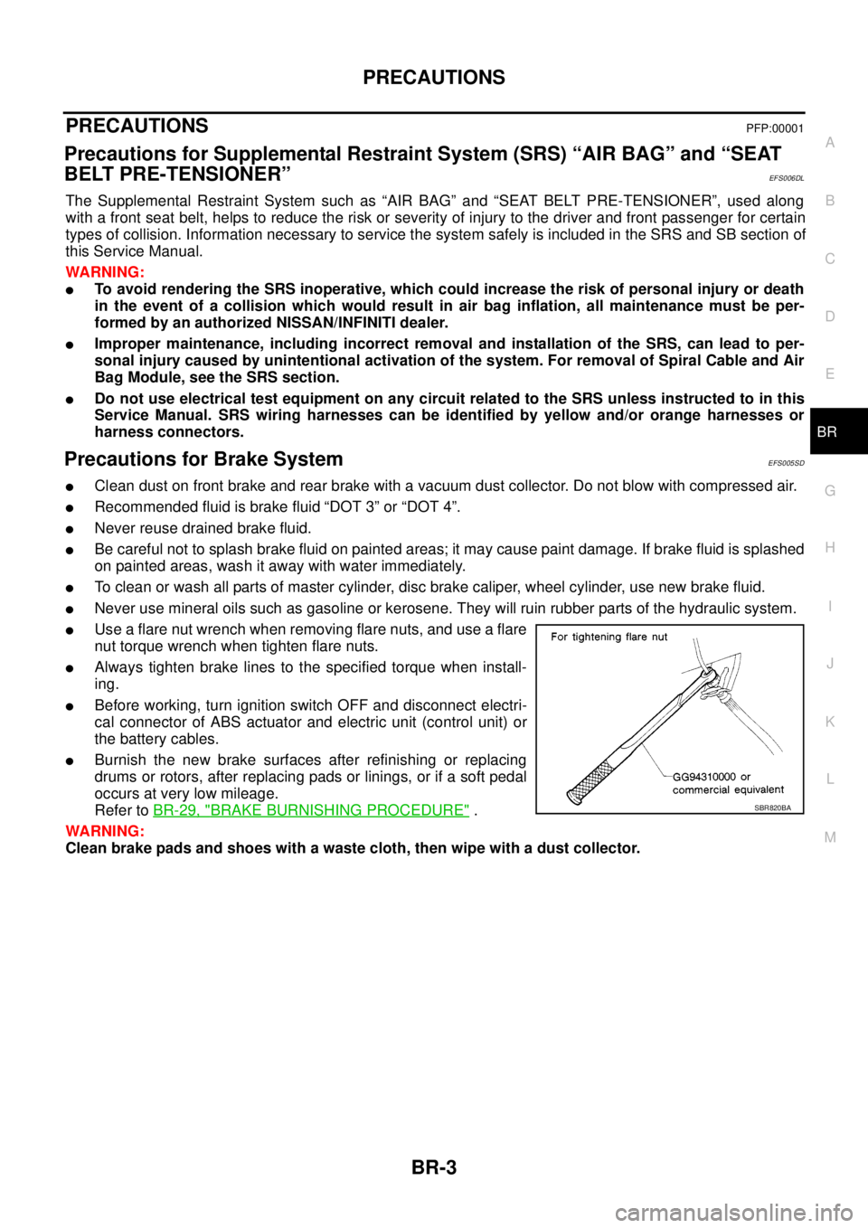
lUse a flare nut wrench when removing flare nuts, and use a flare
nut torque wrench when tighten flare nuts.
lAlways tighten brake lines to the specified torque when install-
ing.
lBefore working, turn ignition switch OFF and disconnect electri-
cal connector of ABS actuator and electric unit (control unit) or
the battery cables.
lBurnish the new brake surfaces after refinishing or replacing
drums or rotors, after replacing pads or linings, or if a soft pedal
occurs at very low mileage.
Refer toBR-29, "
BRAKE BURNISHING PROCEDURE".
WARNING:
Clean brake pads and shoes with a waste cloth, then wipe with a dust collector.SBR820BA
Page 791 of 3171

NOISE, VIBRATION AND HARSHNESS (NVH) TROUBLESHOOTING
BR-5
C
D
E
G
H
I
J
K
L
MA
B
BR
NOISE, VIBRATION AND HARSHNESS (NVH) TROUBLESHOOTINGPFP:00003
NVH Troubleshooting ChartEFS005SF
Use the chart below to help you find the cause of the symptom. If necessary, repair or replace these parts.
´: Applicable Reference page
BR-24
,BR-32
BR-24
,BR-32BR-24BR-28
BR-28
,BR-32
BR-28
,BR-32
BR-28
,BR-32BR-28—
BR-29BR-32
NVHinPRsection
NVH in FFD, RFD section
NVH in FAX, RAX and FSU, RSU section
NVH in WT section
NVH in WT section
NVH in FAX and RAX section
NVH in PS section
Possible cause and
suspected parts
Pads/Lining damaged
Pads/Lining - uneven wear
Shims damaged
Rotor imbalance
Rotor/Drum damage
Rotor runout/Drum inner diameter
Rotor/Drum deformation
Rotor deflection
Rotor rust
Rotor thickness variation
Drum out of round
PROPELLER SHAFT
DIFFERENTIAL
AXLE AND SUSPENSION
TYRES
ROAD WHEEL
DRIVE SHAFT
STEERING
Symptom BrakeNoise´´´ ´´ ´´´
´´
Shake´´´´´
´´
Shimmy, Judder´´´´´´´´ ´´´ ´
Page 796 of 3171
BR-10
BRAKE FLUID
BRAKE FLUID
PFP:KN100
On-board InspectionEFS005SI
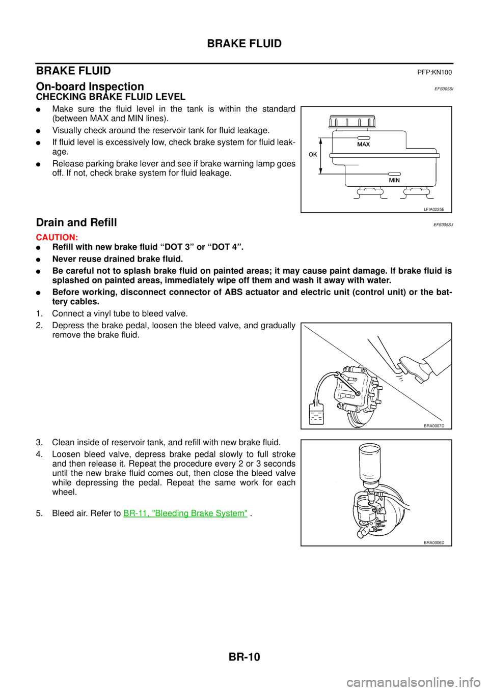
CHECKING BRAKE FLUID LEVEL
lMake sure the fluid level in the tank is within the standard
(between MAX and MIN lines).
lVisually check around the reservoir tank for fluid leakage.
lIf fluid level is excessively low, check brake system for fluid leak-
age.
lRelease parking brake lever and see if brake warning lamp goes
off. If not, check brake system for fluid leakage.
Drain and RefillEFS005SJ
CAUTION:
lRefill with new brake fluid “DOT 3” or “DOT 4”.
lNever reuse drained brake fluid.
lBe careful not to splash brake fluid on painted areas; it may cause paint damage. If brake fluid is
splashed on painted areas, immediately wipe off them and wash it away with water.
lBefore working, disconnect connector of ABS actuator and electric unit (control unit) or the bat-
tery cables.
1. Connect a vinyl tube to bleed valve.
2. Depress the brake pedal, loosen the bleed valve, and gradually
remove the brake fluid.
3. Clean inside of reservoir tank, and refill with new brake fluid.
4. Loosen bleed valve, depress brake pedal slowly to full stroke
and then release it. Repeat the procedure every 2 or 3 seconds
until the new brake fluid comes out, then close the bleed valve
while depressing the pedal. Repeat the same work for each
wheel.
5. Bleed air. Refer toBR-11, "
Bleeding Brake System".
LFIA0225E
BRA0007D
BRA0006D