2005 NISSAN NAVARA weight
[x] Cancel search: weightPage 601 of 3171
HOOD
BL-17
C
D
E
F
G
H
J
K
L
MA
B
BL
Hood Lock Control InspectionEIS00BQ1
CAUTION:
If the hood lock cable is bent or deformed, replace it.
1. Make sure that the hood lock secondary latch is properly engaged with the secondary striker with hood's
own weight.
2. Make sure that the hood lock primary latch is securely engaged with the hood striker with hood's own
weight by dropping it from approx. 200 mm (7.87 in) height.
CAUTION:
Do not drop hood from a height of 300 mm (11.81 in) or more.
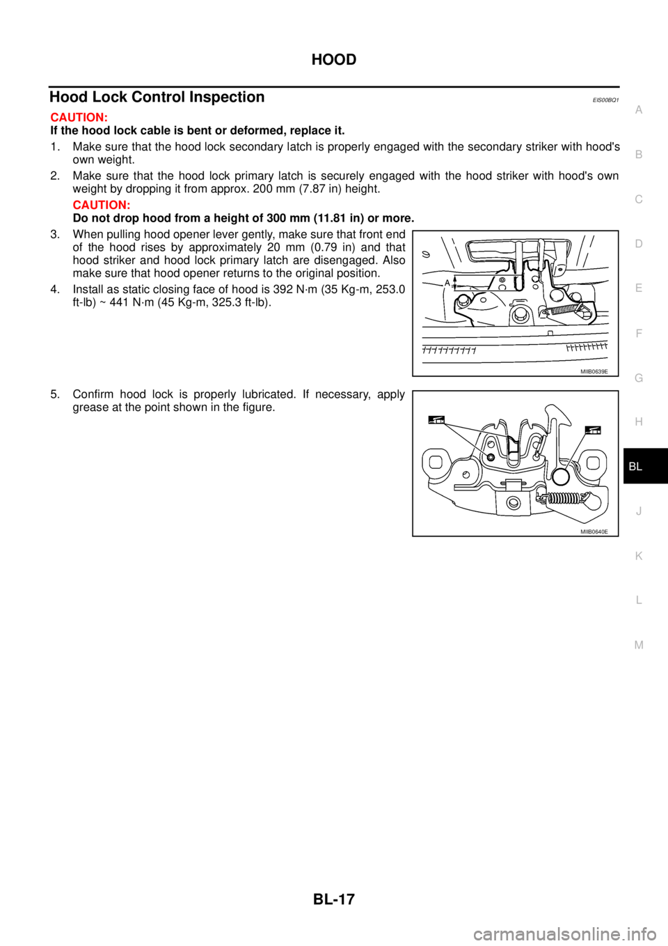
3. When pulling hood opener lever gently, make sure that front end
of the hood rises by approximately 20 mm (0.79 in) and that
hood striker and hood lock primary latch are disengaged. Also
make sure that hood opener returns to the original position.
4. Install as static closing face of hood is 392 N·m (35 Kg-m, 253.0
ft-lb) ~ 441 N·m (45 Kg-m, 325.3 ft-lb).
5. Confirm hood lock is properly lubricated. If necessary, apply
grease at the point shown in the figure.
MIIB0639E
MIIB0640E
Page 704 of 3171
BL-120
DOOR
FRONT DOOR
Longitudinal Clearance and Surface Height Adjustment at Front End
1. Remove the front fender. Refer toBL-20, "Removal and Installation".
2. Loosen the hinge mounting bolts. Raise or lower the front door at rear end to adjust.
REAR DOOR
Longitudinal Clearance and Surface Height Adjustment at Front End
1. Remove the center pillar upper finisher. Refer toEI-35, "CENTER PILLAR UPPER FINISHER".
2. Loosen the lower hinge mounting bolts.
3. From inside the vehicle, loosen the upper hinge mounting nuts. Open the door, and raise or lower the rear
end of the door to adjust.
CAUTION:
After installing, apply touch-up paint (the body color) onto the head of the hinge mounting nuts and
mounting bolts.
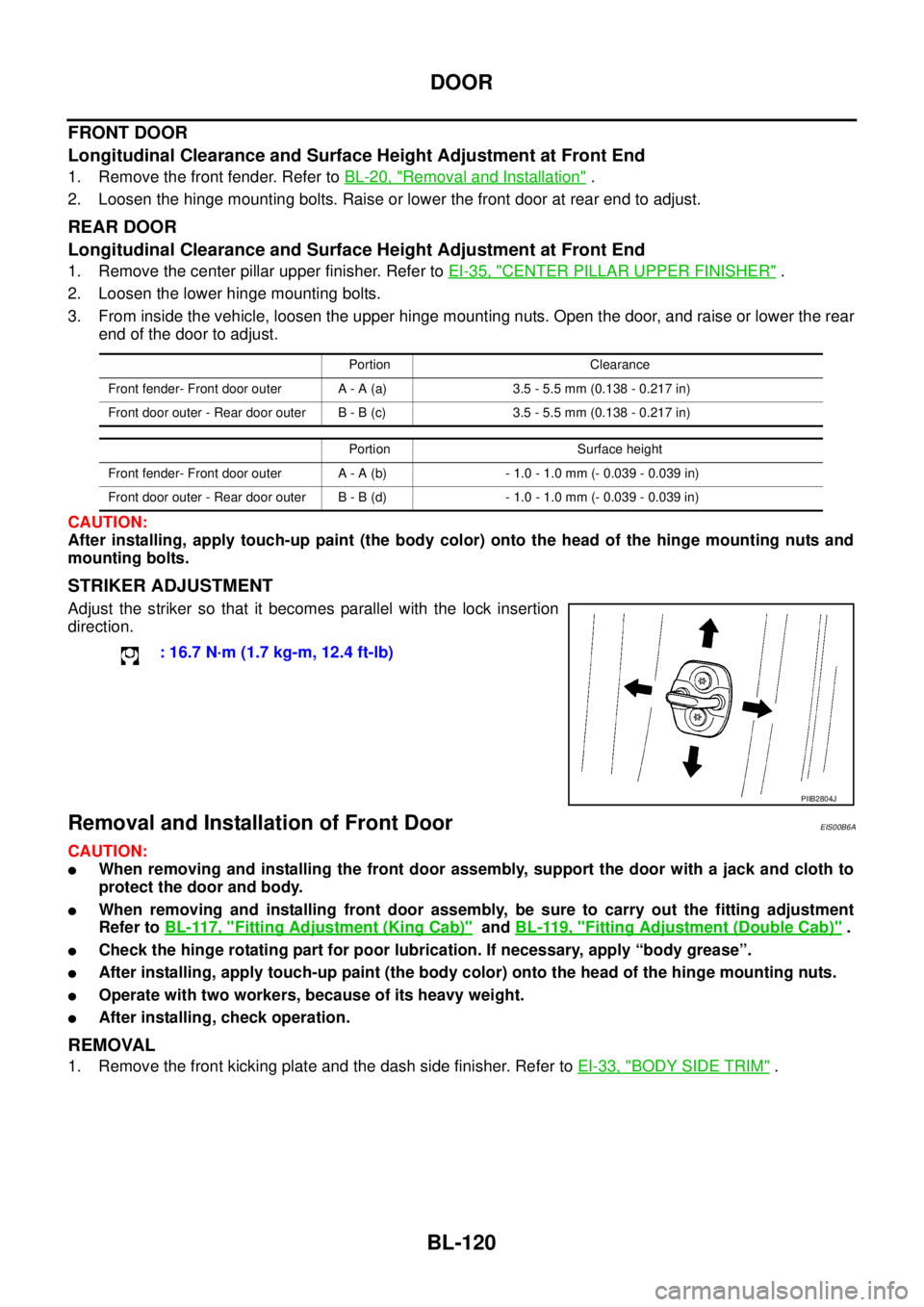
STRIKER ADJUSTMENT
Adjust the striker so that it becomes parallel with the lock insertion
direction.
Removal and Installation of Front DoorEIS00B6A
CAUTION:
lWhen removing and installing the front door assembly, support the door with a jack and cloth to
protect the door and body.
lWhen removing and installing front door assembly, be sure to carry out the fitting adjustment
Refer toBL-117, "
Fitting Adjustment (King Cab)"andBL-119, "Fitting Adjustment (Double Cab)".
lCheck the hinge rotating part for poor lubrication. If necessary, apply “body grease”.
lAfter installing, apply touch-up paint (the body color) onto the head of the hinge mounting nuts.
lOperate with two workers, because of its heavy weight.
lAfter installing, check operation.
REMOVAL
1. Remove the front kicking plate and the dash side finisher. Refer toEI-33, "BODY SIDE TRIM".
Portion Clearance
Front fender- Front door outer A - A (a) 3.5 - 5.5 mm (0.138 - 0.217 in)
Front door outer - Rear door outer B - B (c) 3.5 - 5.5 mm (0.138 - 0.217 in)
Portion Surface height
Front fender- Front door outer A - A (b) - 1.0 - 1.0 mm (- 0.039 - 0.039 in)
Front door outer - Rear door outer B - B (d) - 1.0 - 1.0 mm (- 0.039 - 0.039 in)
: 16.7 N·m (1.7 kg-m, 12.4 ft-lb)
PIIB2804J
Page 705 of 3171
DOOR
BL-121
C
D
E
F
G
H
J
K
L
MA
B
BL
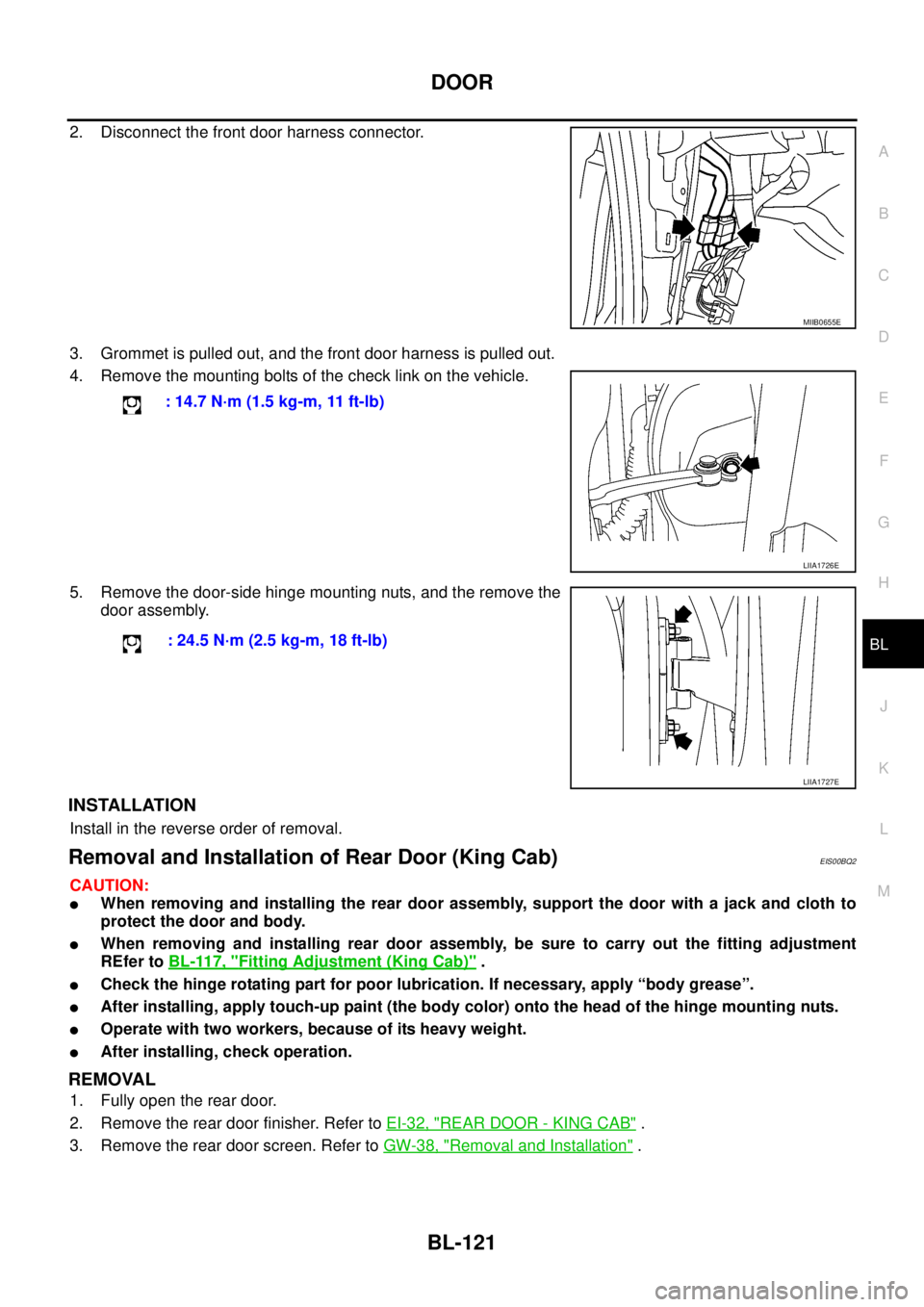
2. Disconnect the front door harness connector.
3. Grommet is pulled out, and the front door harness is pulled out.
4. Remove the mounting bolts of the check link on the vehicle.
5. Remove the door-side hinge mounting nuts, and the remove the
door assembly.
INSTALLATION
Install in the reverse order of removal.
Removal and Installation of Rear Door (King Cab)EIS00BQ2
CAUTION:
lWhen removing and installing the rear door assembly, support the door with a jack and cloth to
protect the door and body.
lWhen removing and installing rear door assembly, be sure to carry out the fitting adjustment
REfer toBL-117, "
Fitting Adjustment (King Cab)".
lCheck the hinge rotating part for poor lubrication. If necessary, apply “body grease”.
lAfter installing, apply touch-up paint (the body color) onto the head of the hinge mounting nuts.
lOperate with two workers, because of its heavy weight.
lAfter installing, check operation.
REMOVAL
1. Fully open the rear door.
2. Remove the rear door finisher. Refer toEI-32, "
REAR DOOR - KING CAB".
3. Remove the rear door screen. Refer toGW-38, "
Removal and Installation".
MIIB0655E
: 14.7 N·m (1.5 kg-m, 11 ft-lb)
LIIA1726E
: 24.5 N·m (2.5 kg-m, 18 ft-lb)
LIIA1727E
Page 707 of 3171
DOOR
BL-123
C
D
E
F
G
H
J
K
L
MA
B
BL
Removal and Installation of Rear Door (Double Cab)EIS00DUN
CAUTION:
lWhen removing and installing the rear door assembly, support the door with a jack and cloth to
protect the door and body.
lWhen removing and installing rear door assembly, be sure to carry out the fitting adjustment
REfer toBL-119, "
Fitting Adjustment (Double Cab)".
lCheck the hinge rotating part for poor lubrication. If necessary, apply “body grease”.
lAfter installing, apply touch-up paint (the body color) onto the head of the hinge mounting nuts.
lOperate with two workers, because of its heavy weight.
lAfter installing, check operation.
REMOVAL
1. Remove the center pillar lower finisher. Refer toEI-33, "BODY SIDE TRIM".
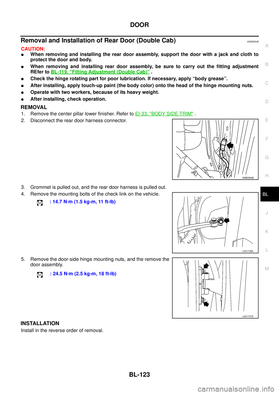
2. Disconnect the rear door harness connector.
3. Grommet is pulled out, and the rear door harness is pulled out.
4. Remove the mounting bolts of the check link on the vehicle.
5. Remove the door-side hinge mounting nuts, and the remove the
door assembly.
INSTALLATION
Install in the reverse order of removal.
MIIB0656E
: 14.7 N·m (1.5 kg-m, 11 ft-lb)
LIIA1726E
: 24.5 N·m (2.5 kg-m, 18 ft-lb)
LIIA1727E
Page 802 of 3171
BR-16
LOAD SENSING VALVE
Inspection
EFS006A8
INSPECTION
1. With the vehicle in unladen condition, a person should sit in driver's seat at the rear. Then he/she should
get out of car gently. (This is to stabilize suspension deflection.)
NOTE:
“Unladen condition”: with full coolant, lubricant, 6 to 8 litters of fuel, spare tyre, jack, and hand tools
loaded.
2. Press load sensing valve against stopper bolt. Check if center-to-center length “L” between adjusting ref-
erence hole and reference pin is as specified below.
lIf measurement is outside the standard, perform following;
loosen mounting bolt of sensor spring bracket. By moving
sensor spring bracket, adjust so that the length “L” comes into
specified range.
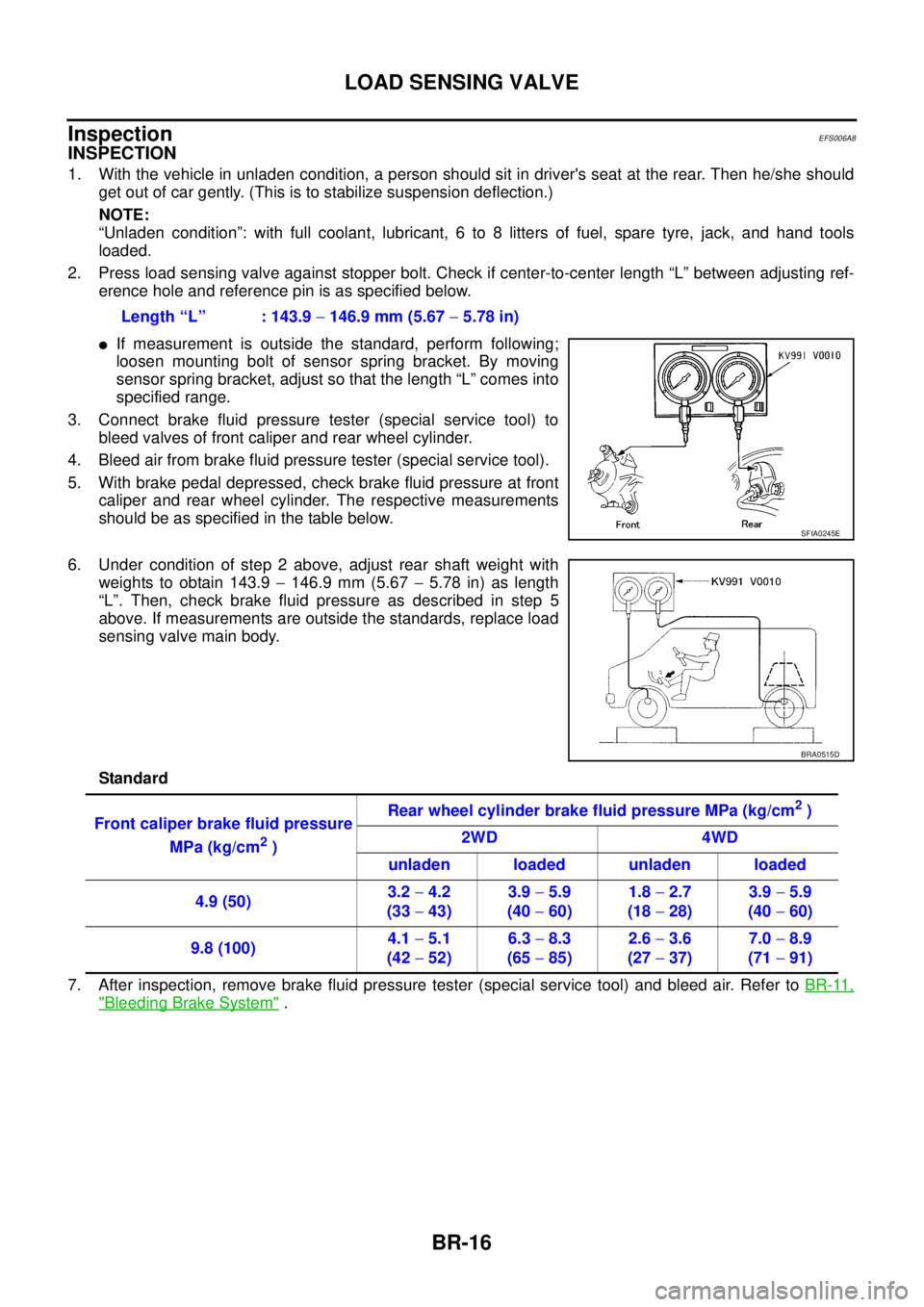
3. Connect brake fluid pressure tester (special service tool) to
bleed valves of front caliper and rear wheel cylinder.
4. Bleed air from brake fluid pressure tester (special service tool).
5. With brake pedal depressed, check brake fluid pressure at front
caliper and rear wheel cylinder. The respective measurements
should be as specified in the table below.
6. Under condition of step 2 above, adjust rear shaft weight with
weights to obtain 143.9-146.9 mm (5.67-5.78 in) as length
“L”. Then, check brake fluid pressure as described in step 5
above. If measurements are outside the standards, replace load
sensing valve main body.
Standard
7. After inspection, remove brake fluid pressure tester (special service tool) and bleed air. Refer toBR-11,
"Bleeding Brake System". Length “L” : 143.9-146.9 mm (5.67-5.78 in)
SFIA0245E
BRA0515D
Front caliper brake fluid pressure
MPa (kg/cm
2)Rear wheel cylinder brake fluid pressure MPa (kg/cm
2)
2WD 4WD
unladen loaded unladen loaded
4.9 (50)3.2-4.2
(33-43)3.9-5.9
(40-60)1.8-2.7
(18-28)3.9-5.9
(40-60)
9.8 (100)4.1-5.1
(42-52)6.3-8.3
(65-85)2.6-3.6
(27-37)7.0-8.9
(71-91)
Page 1626 of 3171
GI-4
PRECAUTIONS
For this reason, if the battery is disconnected or if the battery is discharged, the steering wheel will lock and
steering wheel rotation will become impossible.
If steering wheel rotation is required when battery power is interrupted, follow the procedure below before
starting the repair operation.
OPERATION PROCEDURE
1. Connect both battery cables.
NOTE:
Supply power using jumper cables if battery is discharged.
2. Use the Intelligent Key or mechanical key to turn the ignition switch to the²ACC²position. At this time, the
steering lock will be released.
3. Disconnect both battery cables. The steering lock will remain released and the steering wheel can be
rotated.
4. Perform the necessary repair operation.
5. When the repair work is completed, return the ignition switch to the²LOCK²position before connecting
the battery cables. (At this time, the steering lock mechanism will engage.)
6. Perform a self-diagnosis check of all control units using CONSULT-II.
General PrecautionsEAS001GJ
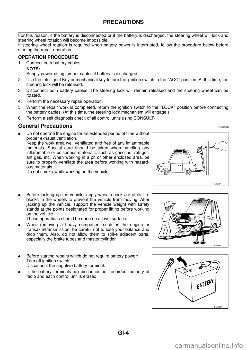
lDo not operate the engine for an extended period of time without
proper exhaust ventilation.
Keep the work area well ventilated and free of any inflammable
materials. Special care should be taken when handling any
inflammable or poisonous materials, such as gasoline, refriger-
ant gas, etc. When working in a pit or other enclosed area, be
sure to properly ventilate the area before working with hazard-
ous materials.
Do not smoke while working on the vehicle.
lBefore jacking up the vehicle, apply wheel chocks or other tire
blocks to the wheels to prevent the vehicle from moving. After
jacking up the vehicle, support the vehicle weight with safety
stands at the points designated for proper lifting before working
on the vehicle.
These operations should be done on a level surface.
lWhen removing a heavy component such as the engine or
transaxle/transmission, be careful not to lose your balance and
drop them. Also, do not allow them to strike adjacent parts,
especially the brake tubes and master cylinder.
lBefore starting repairs which do not require battery power:
Turn off ignition switch.
Disconnect the negative battery terminal.
lIf the battery terminals are disconnected, recorded memory of
radio and each control unit is erased.
SGI285
SGI231
SEF289H
Page 1642 of 3171

GI-20
HOW TO USE THIS MANUAL
Detectable Lines and Non-Detectable Lines
In some wiring diagrams, two kinds of lines, representing wires, with different weight are used.
lA line with regular weight (wider line) represents a “detectable
line for DTC (Diagnostic Trouble Code)”. A “detectable line for
DTC” is a circuit in which ECM can detect its malfunctions with
the on board diagnostic system.
lA line with less weight (thinner line) represents a “non-detect-
able line for DTC”. A “non-detectable line for DTC” is a circuit in
which ECM cannot detect its malfunctions with the on board
diagnostic system.
SGI862-B
Page 2111 of 3171
LT-28
HEADLAMP -CONVENTIONAL TYPE-
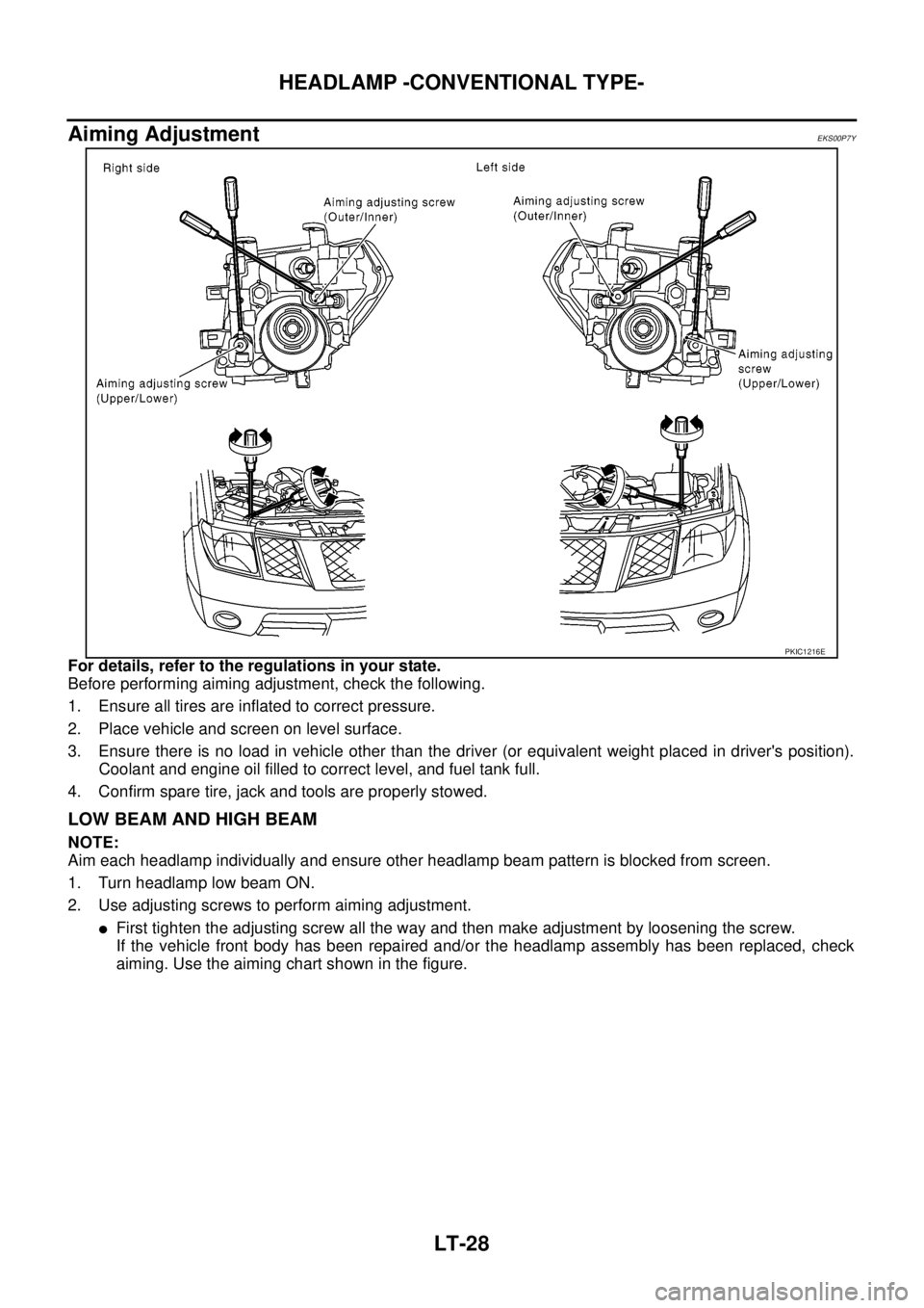
Aiming Adjustment
EKS00P7Y
For details, refer to the regulations in your state.
Before performing aiming adjustment, check the following.
1. Ensure all tires are inflated to correct pressure.
2. Place vehicle and screen on level surface.
3. Ensure there is no load in vehicle other than the driver (or equivalent weight placed in driver's position).
Coolant and engine oil filled to correct level, and fuel tank full.
4. Confirm spare tire, jack and tools are properly stowed.
LOW BEAM AND HIGH BEAM
NOTE:
Aim each headlamp individually and ensure other headlamp beam pattern is blocked from screen.
1. Turn headlamp low beam ON.
2. Use adjusting screws to perform aiming adjustment.
lFirst tighten the adjusting screw all the way and then make adjustment by loosening the screw.
If the vehicle front body has been repaired and/or the headlamp assembly has been replaced, check
aiming. Use the aiming chart shown in the figure.
PKIC1216E