2005 NISSAN NAVARA Em-49
[x] Cancel search: Em-49Page 1248 of 3171

EC-268
DTC P1275 FUEL PUMP
Component Inspection
EBS01KKF
FUEL PUMP
1. Disconnect fuel pump harness connector.
2. Check resistance between fuel pump terminals 1 and 2.
3. If NG, replace fuel pump.
Removal and InstallationEBS01KKG
FUEL PUMP
Refer toEM-49, "FUEL PUMP". Resistance: 1.5 - 3.0W[at 10 - 60°C (50 - 140°F)]
PBIB0417E
Page 1431 of 3171
FUEL PUMP
EM-49
C
D
E
F
G
H
I
J
K
L
MA
EM
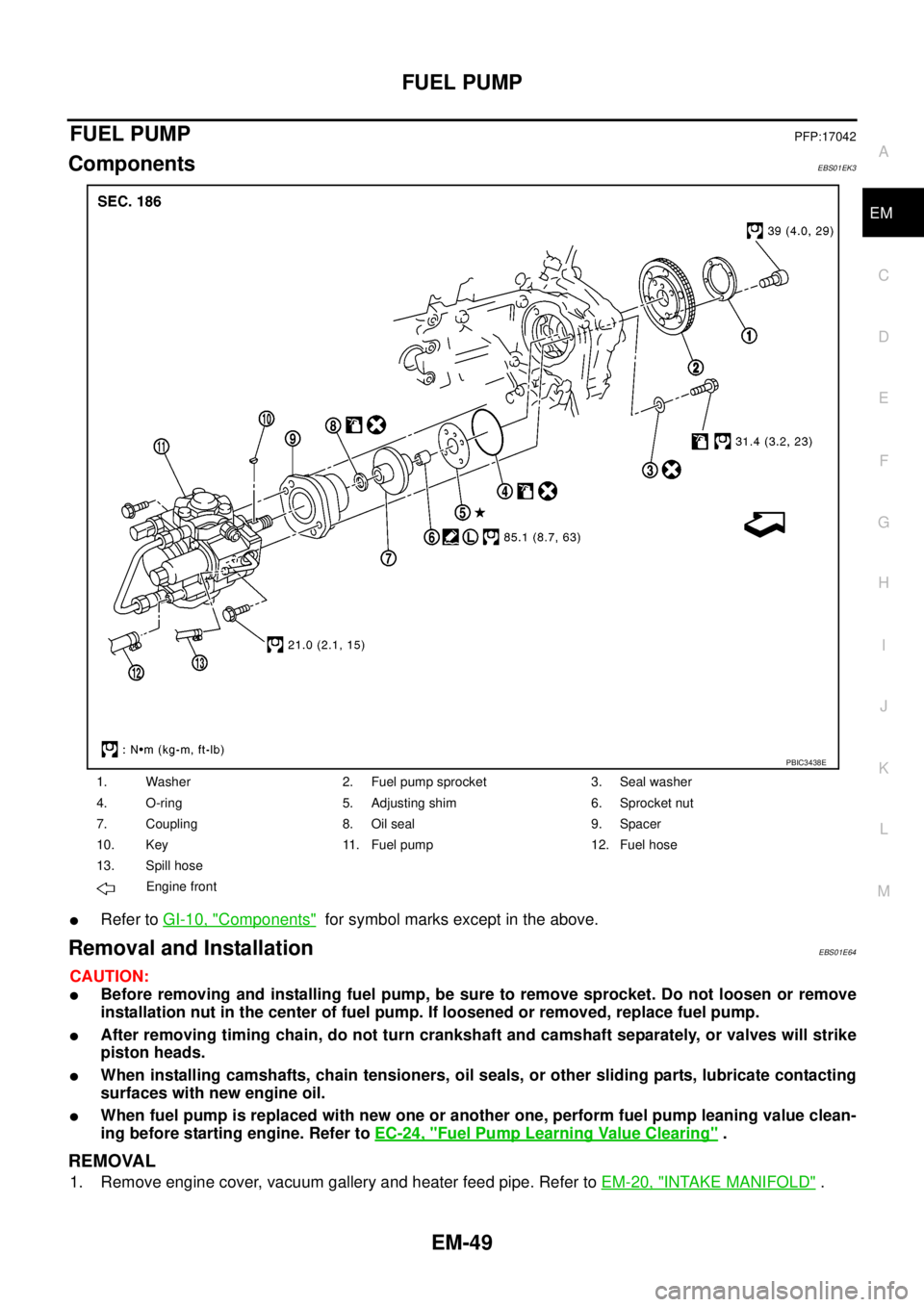
FUEL PUMPPFP:17042
ComponentsEBS01EK3
lRefer toGI-10, "Components"for symbol marks except in the above.
Removal and InstallationEBS01E64
CAUTION:
lBefore removing and installing fuel pump, be sure to remove sprocket. Do not loosen or remove
installation nut in the center of fuel pump. If loosened or removed, replace fuel pump.
lAfter removing timing chain, do not turn crankshaft and camshaft separately, or valves will strike
piston heads.
lWhen installing camshafts, chain tensioners, oil seals, or other sliding parts, lubricate contacting
surfaces with new engine oil.
lWhen fuel pump is replaced with new one or another one, perform fuel pump leaning value clean-
ing before starting engine. Refer toEC-24, "
Fuel Pump Learning Value Clearing".
REMOVAL
1. Remove engine cover, vacuum gallery and heater feed pipe. Refer toEM-20, "INTAKE MANIFOLD".
1. Washer 2. Fuel pump sprocket 3. Seal washer
4. O-ring 5. Adjusting shim 6. Sprocket nut
7. Coupling 8. Oil seal 9. Spacer
10. Key 11. Fuel pump 12. Fuel hose
13. Spill hose
Engine front
PBIC3438E
Page 1455 of 3171
SECONDARY TIMING CHAIN
EM-73
C
D
E
F
G
H
I
J
K
L
MA
EM
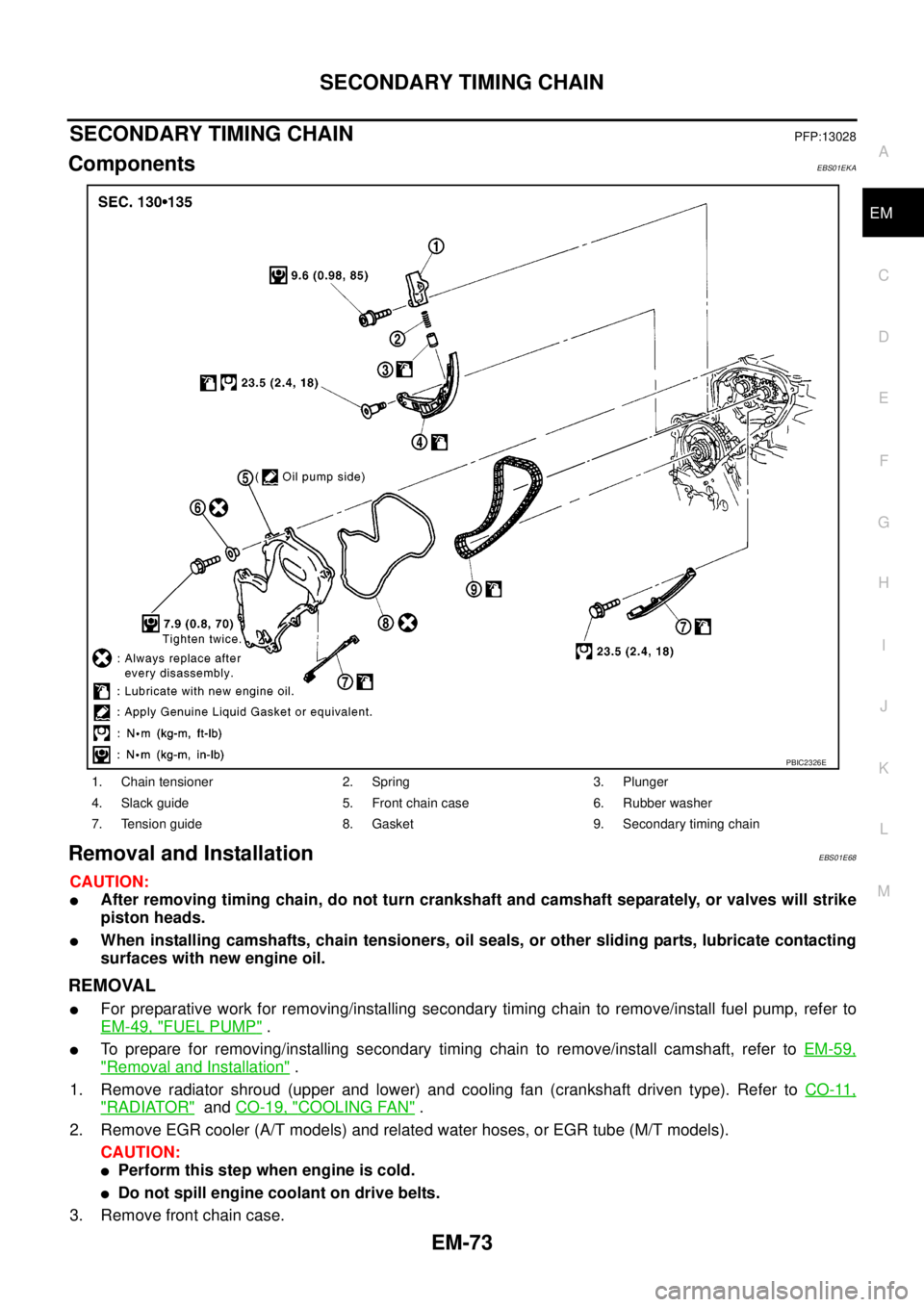
SECONDARY TIMING CHAINPFP:13028
ComponentsEBS01EKA
Removal and InstallationEBS01E68
CAUTION:
lAfter removing timing chain, do not turn crankshaft and camshaft separately, or valves will strike
piston heads.
lWhen installing camshafts, chain tensioners, oil seals, or other sliding parts, lubricate contacting
surfaces with new engine oil.
REMOVAL
lFor preparative work for removing/installing secondary timing chain to remove/install fuel pump, refer to
EM-49, "
FUEL PUMP".
lTo prepare for removing/installing secondary timing chain to remove/install camshaft, refer toEM-59,
"Removal and Installation".
1. Remove radiator shroud (upper and lower) and cooling fan (crankshaft driven type). Refer toCO-11,
"RADIATOR"andCO-19, "COOLING FAN".
2. Remove EGR cooler (A/T models) and related water hoses, or EGR tube (M/T models).
CAUTION:
lPerform this step when engine is cold.
lDo not spill engine coolant on drive belts.
3. Remove front chain case.
1. Chain tensioner 2. Spring 3. Plunger
4. Slack guide 5. Front chain case 6. Rubber washer
7. Tension guide 8. Gasket 9. Secondary timing chain
PBIC2326E
Page 1465 of 3171
PRIMARY TIMING CHAIN
EM-83
C
D
E
F
G
H
I
J
K
L
MA
EM
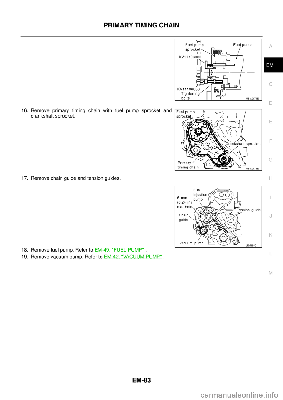
16. Remove primary timing chain with fuel pump sprocket and
crankshaft sprocket.
17. Remove chain guide and tension guides.
18. Remove fuel pump. Refer toEM-49, "
FUEL PUMP".
19. Remove vacuum pump. Refer toEM-42, "
VACUUM PUMP".
MBIA0074E
MBIA0079E
JEM885G
Page 1469 of 3171
PRIMARY TIMING CHAIN
EM-87
C
D
E
F
G
H
I
J
K
L
MA
EM
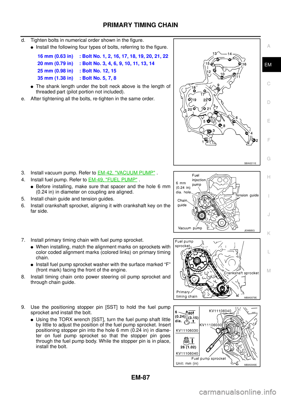
d. Tighten bolts in numerical order shown in the figure.
lInstall the following four types of bolts, referring to the figure.
lThe shank length under the bolt neck above is the length of
threaded part (pilot portion not included).
e. After tightening all the bolts, re-tighten in the same order.
3. Install vacuum pump. Refer toEM-42, "
VACUUM PUMP".
4. Install fuel pump. Refer toEM-49, "
FUEL PUMP".
lBefore installing, make sure that spacer and the hole 6 mm
(0.24 in) in diameter on coupling are aligned.
5. Install chain guide and tension guides.
6. Install crankshaft sprocket, aligning it with crankshaft key on the
far side.
7. Install primary timing chain with fuel pump sprocket.
lWhen installing, match the alignment marks on sprockets with
color coded alignment marks (colored links) on primary timing
chain.
lInstall fuel pump sprocket washer with the surface marked “F”
(front mark) facing the front of the engine.
8. Install timing chain onto power steering oil pump sprocket and
through chain guide.
9. Use the positioning stopper pin [SST] to hold the fuel pump
sprocket and install the bolt.
lUsing the TORX wrench [SST], turn the fuel pump shaft little
by little to adjust the position of the fuel pump sprocket. Insert
positioning stopper pin into the hole 6 mm (0.24 in) in diame-
ter on fuel pump sprocket so that the stopper pin goes
through the fuel pump body. While the stopper pin is in place,
install the bolt.16 mm (0.63 in) : Bolt No. 1, 2, 16, 17, 18, 19, 20, 21, 22
20mm(0.79in) :BoltNo.3,4,6,9,10,11,13,14
25 mm (0.98 in) : Bolt No. 12, 15
35 mm (1.38 in) : Bolt No. 5, 7, 8
SBIA0211E
JEM885G
MBIA0079E
MBIA0049E
Page 1494 of 3171
EM-112
CYLINDER BLOCK
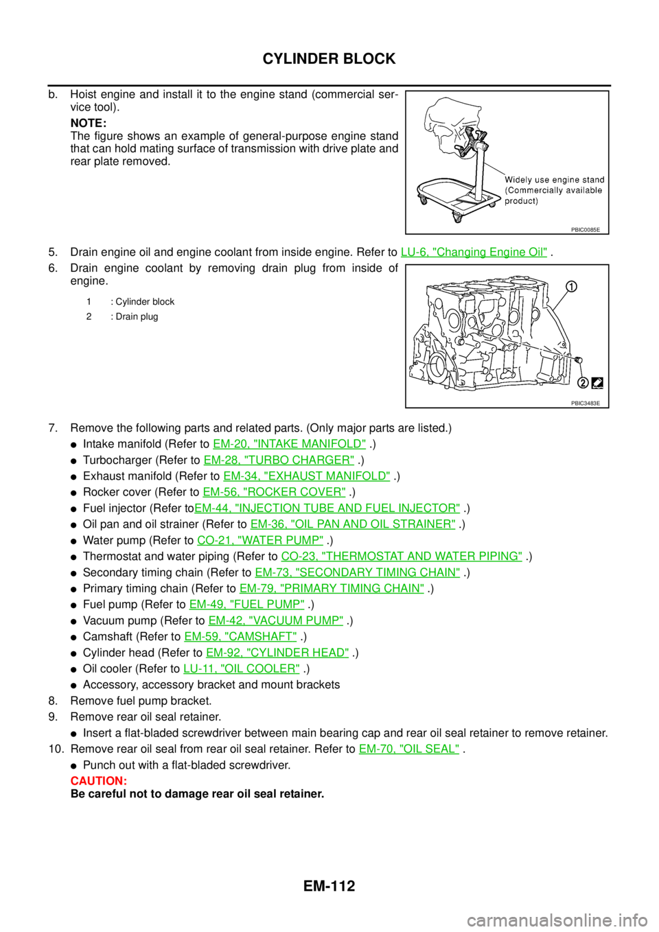
b. Hoist engine and install it to the engine stand (commercial ser-
vice tool).
NOTE:
The figure shows an example of general-purpose engine stand
that can hold mating surface of transmission with drive plate and
rear plate removed.
5. Drain engine oil and engine coolant from inside engine. Refer toLU-6, "
Changing Engine Oil".
6. Drain engine coolant by removing drain plug from inside of
engine.
7. Remove the following parts and related parts. (Only major parts are listed.)
lIntake manifold (Refer toEM-20, "INTAKE MANIFOLD".)
lTurbocharger (Refer toEM-28, "TURBO CHARGER".)
lExhaust manifold (Refer toEM-34, "EXHAUST MANIFOLD".)
lRocker cover (Refer toEM-56, "ROCKER COVER".)
lFuel injector (Refer toEM-44, "INJECTION TUBE AND FUEL INJECTOR".)
lOil pan and oil strainer (Refer toEM-36, "OIL PAN AND OIL STRAINER".)
lWater pump (Refer toCO-21, "WATER PUMP".)
lThermostat and water piping (Refer toCO-23, "THERMOSTAT AND WATER PIPING".)
lSecondary timing chain (Refer toEM-73, "SECONDARY TIMING CHAIN".)
lPrimary timing chain (Refer toEM-79, "PRIMARY TIMING CHAIN".)
lFuel pump (Refer toEM-49, "FUEL PUMP".)
lVacuum pump (Refer toEM-42, "VACUUM PUMP".)
lCamshaft (Refer toEM-59, "CAMSHAFT".)
lCylinder head (Refer toEM-92, "CYLINDER HEAD".)
lOil cooler (Refer toLU-11, "OIL COOLER".)
lAccessory, accessory bracket and mount brackets
8. Remove fuel pump bracket.
9. Remove rear oil seal retainer.
lInsert a flat-bladed screwdriver between main bearing cap and rear oil seal retainer to remove retainer.
10. Remove rear oil seal from rear oil seal retainer. Refer toEM-70, "
OIL SEAL".
lPunch out with a flat-bladed screwdriver.
CAUTION:
Be careful not to damage rear oil seal retainer.
PBIC0085E
1 : Cylinder block
2 : Drain plug
PBIC3483E
Page 1755 of 3171
IDX-3
A
C
D
E
F
G
H
I
J
K
L B
IDX
ALPHABETICAL INDEX
C
Camshaft ...........................................................EM-59
Camshaft inspection ..........................................EM-60
Camshaft position sensor (CMPS) .....EC-82,EC-171,
EC-177
CAN ....................................................................DI-65
CAN - Wiring diagram ...........EC-80,LAN-26,LAN-44,
LAN-56
,LAN-68,LAN-82,LAN-96,LAN-112,LAN-125,
LAN-139
,LAN-152,LAN-166,LAN-181,LAN-198,
LAN-213
,LAN-230,LAN-248,LAN-267,LAN-279
CAN (Controller Area Network) ..BL-25,BL-59,RF-13
CAN communication .....EC-22,EC-79,AT-91,TF-19,
TF-82
,RFD-43,RFD-69,BRC-28,BL-25,BL-59,RF-13,
LT-88
CHARGE - Wiring diagram ................................SC-15
Charging system ................................................SC-14
Chassis and body maintenance ........................MA-28
CHIME - Wiring diagram .....................................DI-53
CIGAR - Wiring diagram ..................................WW-55
Cigarette lighter ...............................................WW-55
Circuit breaker ...................................................PG-74
CKPS - Wiring diagram .....................EC-161,EC-167
Clutch cover .......................................................CL-17
Clutch disc .........................................................CL-17
Clutch master cylinder .........................................CL-9
Clutch operating cylinder ...................................CL-11
Clutch pedal .........................................................CL-6
CMPS - Wiring diagram .....................EC-173,EC-179
Coil spring (front) .............................................FSU-10
Collision diagnosis ...........................................SRS-56
Combination lamp, front, removal and installation ........
LT-30
Combination lamp, rear, removal and installation ........
LT-144
Combination meter ...............................................DI-4
Combination switch ..........................................LT-114
COMBSW - Wiring diagram ..............................LT-114
COMPAS - Wiring diagram .................................DI-68
Compass ............................................................DI-66
Component Location (auto A/C) .......ATC-36,MTC-36
Compression pressure ......................................EM-92
Compressor clutch removal and installation .ATC-143,
MTC-123
Compressor mounting ..................ATC-142,MTC-122
Compressor special service tool .......ATC-16,MTC-16
Condenser ....................................ATC-147,MTC-127
Connecting rod ................................................EM-127
Connecting rod bearing clearance ...................EM-131
Connecting rod bushing clearance ..................EM-127
Console box - See Instrument panel ...................IP-10
CONSULT for all-mode 4WD .............................TF-44
CONSULT-II for engine .....................................EC-59
Control units (terminal arrangement) .................PG-78
Control valve (A/T) .............................................AT-33
Controller Area Network (CAN) ..BL-25,BL-59,RF-13
Converter housing installation .........................AT-250
COOL/F - Wiring diagram ................................EC-135
Cooling circuit (engine) ........................................CO-6
Cooling fan ........................................................CO-19
Cooling fan motor ............................................EC-141
Cooling unit (A/C evaporator) ......ATC-124,ATC-149,
MTC-103
,MTC-129
Counter gear (M/T) ............................................MT-21
Coupling sleeve (M/T) ........................................MT-21
Crankcase ventilation system ............................EC-21
Crankshaft position sensor (TDC) ......EC-82,EC-159,
EC-165
Cylinder block .................................................EM-110
Cylinder block boring ......................................EM-129
Cylinder head ....................................................EM-92
Cylinder head bolt tightening ............................EM-96
Cylinder head gasket selection .........................EM-96
D
Data link connector for Consult ..........................EC-59
Daytime light system ...........................................LT-31
Daytime running light - See Daytime light systemLT-31
Diagnosis sensor unit .....................................SRS-48
Diagnostic trouble code (DTC) ..........................EC-27
Diagnostic trouble code (DTC) for OBD system ..EC-6
Diagnostic trouble code (DTC) inspection priority chart
EC-37
Differential gear oil replacement ...........MA-33,MA-34
DIFLOC - Wiring diagram ...............................RFD-46
Dimensions .........................................................GI-60
Direct clutch solenoid valve ...............AT-142,AT-144
Display and amp.assembly ...............ATC-60,MTC-55
Dome light - See Interior lamp ..........................LT-145
Door glass ...........................................GW-35,GW-38
Door lock ..........................................................BL-126
Door mirror lamp ...............................................LT-145
Door trim .............................................................EI-30
Door, front .............................BL-118,BL-120,GW-35
Door, rear ............................................BL-118,GW-38
Drive belt ...........................................................EM-12
Drive chain (Transfer) .........................TF-114,TF-120
Driver air bag ..................................................SRS-36
DTRL - Wiring diagram .......................................LT-35
Duct and grilles .............................ATC-134,MTC-113
E
ECM input/output signal .....................................EC-52
ECM power supply .............................................EC-71
ECM relay ........................................................EC-232
ECTS - Wiring diagram ....................................EC-105
EGR function ...................................................EC-302
EGR volume control valve ...............................EC-302
EGRC/V - Wiring diagram ................................EC-304
Electric sunroof ..................................................RF-10
Electrical units location ......................................PG-71
Electronic fuel injection pump ...........................EM-49
Engine control circuit diagram ...........................EC-50
Engine control component parts location ...........EC-46
Engine control module (ECM) ...........EC-213,EC-215,
EC-269