Page 2280 of 3171
DESCRIPTION
MA-5
C
D
E
F
G
H
I
J
K
MA
B
MA
DESCRIPTIONPFP:00000
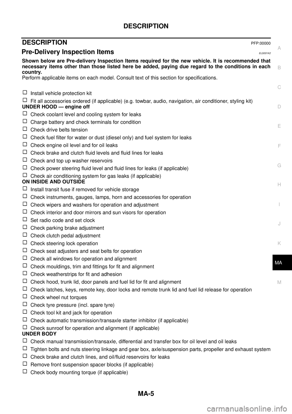
Pre-Delivery Inspection ItemsELS001K2
Shown below are Pre-delivery Inspection Items required for the new vehicle. It is recommended that
necessary items other than those listed here be added, paying due regard to the conditions in each
country.
Perform applicable items on each model. Consult text of this section for specifications.
Install vehicle protection kit
Fit all accessories ordered (if applicable) (e.g. towbar, audio, navigation, air conditioner, styling kit)
UNDER HOOD — engine off
Check coolant level and cooling system for leaks
Charge battery and check terminals for condition
Check drive belts tension
Check fuel filter for water or dust (diesel only) and fuel system for leaks
Check engine oil level and for oil leaks
Check brake and clutch fluid levels and fluid lines for leaks
Check and top up washer reservoirs
Check power steering fluid level and fluid lines for leaks (if applicable)
Check air conditioning system for gas leaks (if applicable)
ON INSIDE AND OUTSIDE
Install transit fuse if removed for vehicle storage
Check instruments, gauges, lamps, horn and accessories for operation
Check wipers and washers for operation and adjustment
Check interior and door mirrors and sun visors for operation
Set radio code and set clock
Check parking brake adjustment
Check clutch pedal adjustment
Check steering lock operation
Check seat adjusters and seat belts for operation
Check all windows for operation and alignment
Check mouldings, trim and fittings for fit and alignment
Check weatherstrips for fit and adhesion
Check hood, trunk lid, door panels and fuel lid for fit and alignment
Check latches, keys, remote key, door locks and remote trunk lid and fuel lid release for operation
Check wheel nut torques
Check tyre pressure (incl. spare tyre)
Check tool kit and jack for operation
Check automatic transmission/transaxle starter inhibitor (if applicable)
Check sunroof for operation and alignment (if applicable)
UNDER BODY
Check manual transmission/transaxle, differential and transfer box for oil level and oil leaks
Tighten bolts and nuts steering linkage and gear box, axle/suspension parts, propeller and exhaust system
Check brake and clutch lines, and oil/fluid reservoirs for leaks
Remove front suspension spacer blocks (if applicable)
Check body mounting torque (if applicable)
Page 2281 of 3171
MA-6
DESCRIPTION
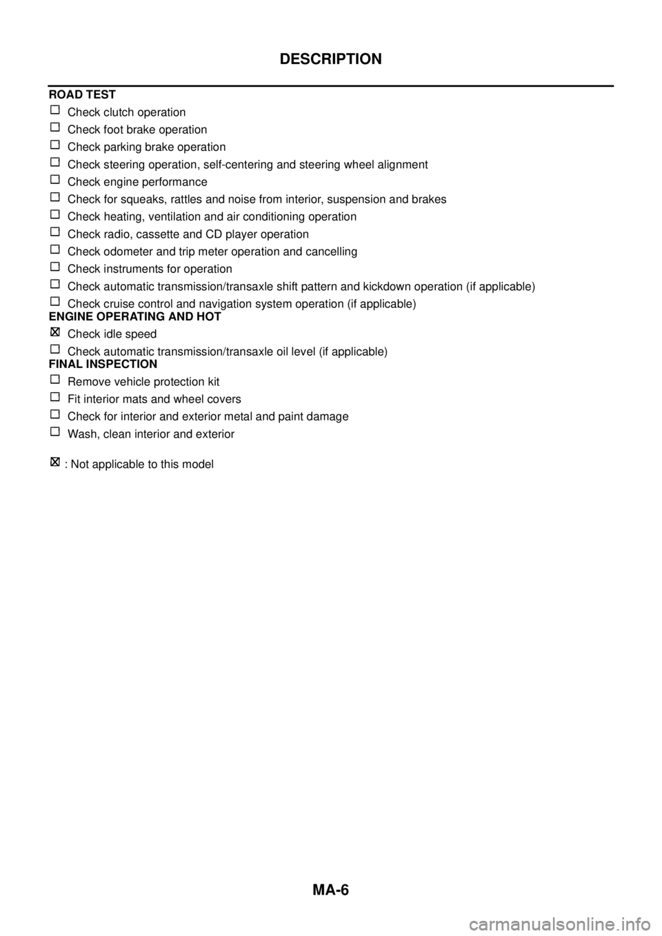
ROAD TEST
Check clutch operation
Check foot brake operation
Check parking brake operation
Check steering operation, self-centering and steering wheel alignment
Check engine performance
Check for squeaks, rattles and noise from interior, suspension and brakes
Check heating, ventilation and air conditioning operation
Check radio, cassette and CD player operation
Check odometer and trip meter operation and cancelling
Check instruments for operation
Check automatic transmission/transaxle shift pattern and kickdown operation (if applicable)
Check cruise control and navigation system operation (if applicable)
ENGINE OPERATING AND HOT
Check idle speed
Check automatic transmission/transaxle oil level (if applicable)
FINAL INSPECTION
Remove vehicle protection kit
Fit interior mats and wheel covers
Check for interior and exterior metal and paint damage
Wash, clean interior and exterior
: Not applicable to this model
Page 2392 of 3171
PRECAUTIONS
MTC-5
C
D
E
F
G
H
I
K
L
MA
B
MTC
lIf the vehicle is within the warranty period, the air conditioner warranty is void. Please contact NISSAN
Customer Affairs for further assistance.
General Refrigerant PrecautionsEJS00628
WARNING:
lDo not release refrigerant into the air. Use approved recovery/recycling equipment to capture the
refrigerant every time an air conditioning system is discharged.
lAlways wear eye and hand protection (goggles and gloves) when working with any refrigerant or
air conditioning system.
lDo not store or heat refrigerant containers above 52°C.
lDo not heat a refrigerant container with an open flame; if container warming is required, place the
bottom of the container in a warm pail of water.
lDo not intentionally drop, puncture, or incinerate refrigerant containers.
lKeep refrigerant away from open flames: poisonous gas will be produced if refrigerant burns.
lRefrigerant will displace oxygen, therefore be certain to work in well ventilated areas to prevent
suffocation.
lDo not pressure test or leak test HFC-134a (R-134a) service equipment and/or vehicle air condi-
tioning systems with compressed air during repair. Some mixtures of air and HFC-134a (R-134a)
have been shown to be combustible at elevated pressures. These mixtures, if ignited, may cause
injury or property damage. Additional health and safety information may be obtained from refriger-
ant manufacturers.
Precautions for Refrigerant ConnectionEJS005FL
A new type refrigerant connection has been introduced to all refrigerant lines except the following locations.
lExpansion valve to cooling unit
lEvaporator pipes to evaporator (inside cooling unit)
lRefrigerant pressure sensor
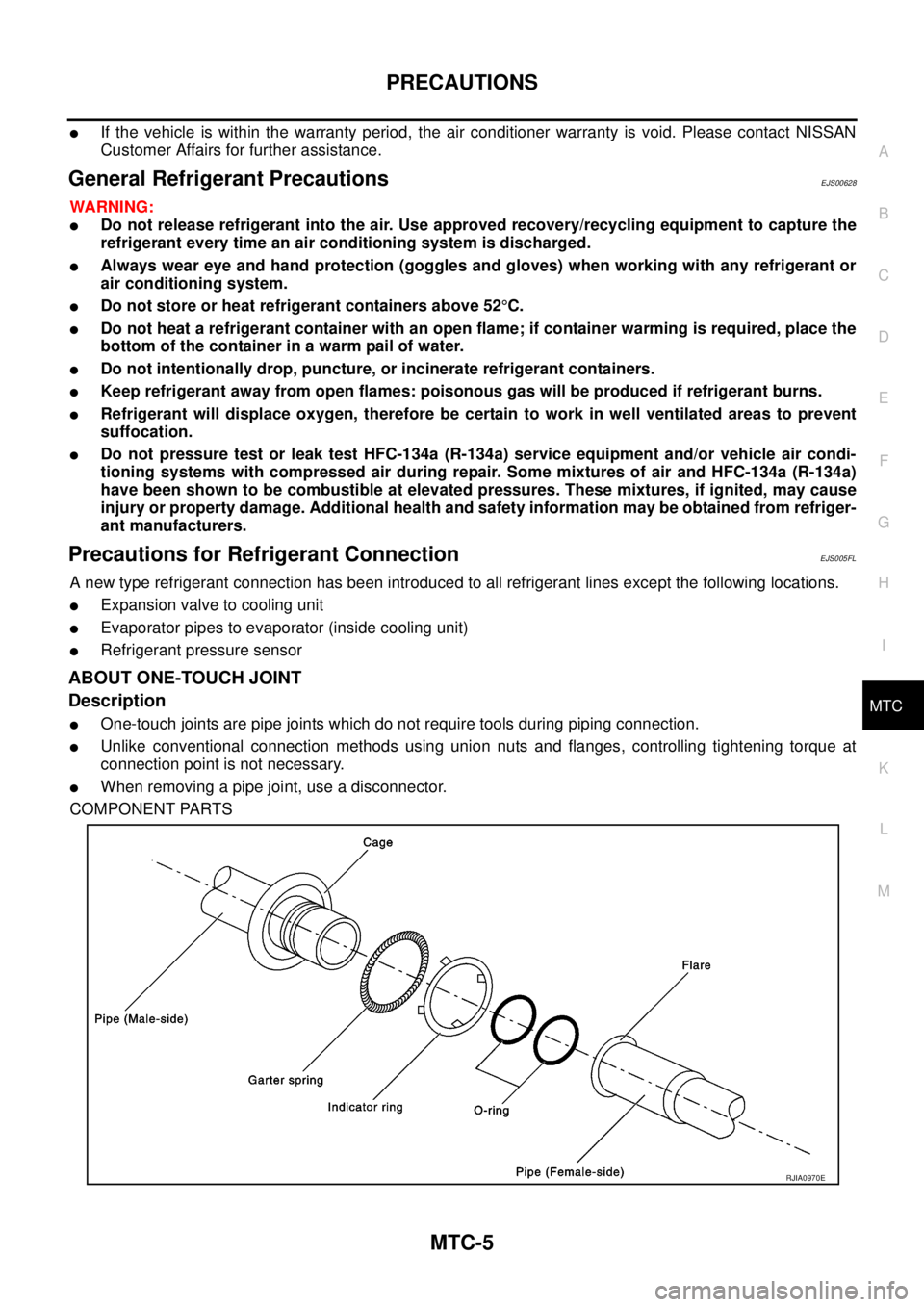
ABOUT ONE-TOUCH JOINT
Description
lOne-touch joints are pipe joints which do not require tools during piping connection.
lUnlike conventional connection methods using union nuts and flanges, controlling tightening torque at
connection point is not necessary.
lWhen removing a pipe joint, use a disconnector.
COMPONENT PARTS
RJIA0970E
Page 2476 of 3171
TROUBLE DIAGNOSIS
MTC-89
C
D
E
F
G
H
I
K
L
MA
B
MTC
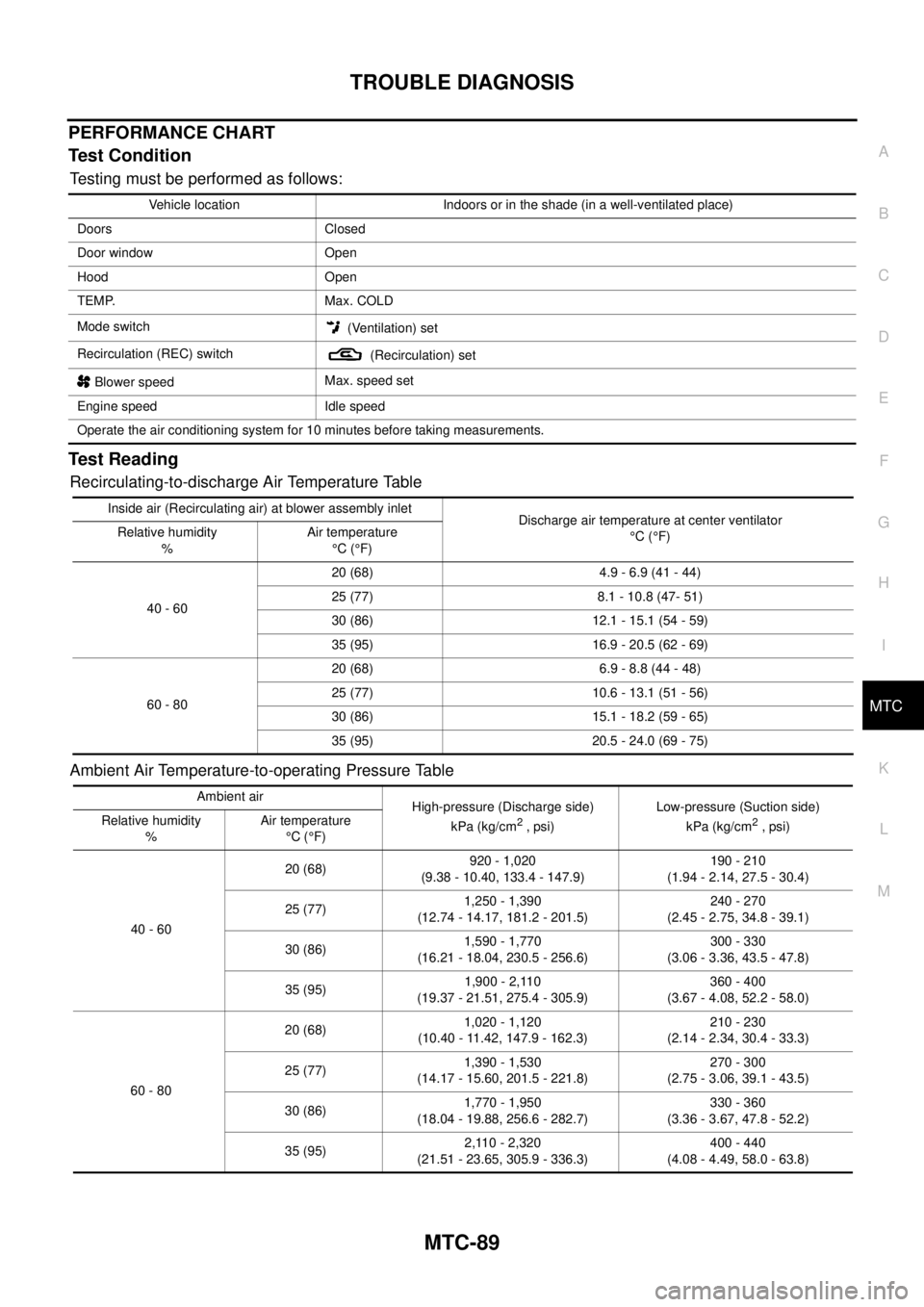
PERFORMANCE CHART
Test Condition
Testing must be performed as follows:
Test Reading
Recirculating-to-discharge Air Temperature Table
Ambient Air Temperature-to-operating Pressure Table
Vehicle location Indoors or in the shade (in a well-ventilated place)
Doors Closed
Door window Open
Hood Open
TEMP. Max. COLD
Mode switch
(Ventilation) set
Recirculation (REC) switch
(Recirculation) set
Blower speedMax. speed set
Engine speed Idle speed
Operate the air conditioning system for 10 minutes before taking measurements.
Inside air (Recirculating air) at blower assembly inlet
Discharge air temperature at center ventilator
°C(°F) Relative humidity
%Air temperature
°C(°F)
40 - 6020 (68) 4.9 - 6.9 (41 - 44)
25 (77) 8.1 - 10.8 (47- 51)
30 (86) 12.1 - 15.1 (54 - 59)
35 (95) 16.9 - 20.5 (62 - 69)
60 - 8020 (68) 6.9 - 8.8 (44 - 48)
25 (77) 10.6 - 13.1 (51 - 56)
30 (86) 15.1 - 18.2 (59 - 65)
35 (95) 20.5 - 24.0 (69 - 75)
Ambient air
High-pressure (Discharge side)
kPa (kg/cm
2,psi)Low-pressure (Suction side)
kPa (kg/cm2, psi) Relative humidity
%Air temperature
°C(°F)
40 - 6020 (68)920 - 1,020
(9.38 - 10.40, 133.4 - 147.9)190 - 210
(1.94 - 2.14, 27.5 - 30.4)
25 (77)1,250 - 1,390
(12.74 - 14.17, 181.2 - 201.5)240 - 270
(2.45 - 2.75, 34.8 - 39.1)
30 (86)1,590 - 1,770
(16.21 - 18.04, 230.5 - 256.6)300 - 330
(3.06 - 3.36, 43.5 - 47.8)
35 (95)1,900 - 2,110
(19.37 - 21.51, 275.4 - 305.9)360 - 400
(3.67 - 4.08, 52.2 - 58.0)
60 - 8020 (68)1,020 - 1,120
(10.40 - 11.42, 147.9 - 162.3)210 - 230
(2.14 - 2.34, 30.4 - 33.3)
25 (77)1,390 - 1,530
(14.17 - 15.60, 201.5 - 221.8)270 - 300
(2.75 - 3.06, 39.1 - 43.5)
30 (86)1,770 - 1,950
(18.04 - 19.88, 256.6 - 282.7)330 - 360
(3.36 - 3.67, 47.8 - 52.2)
35 (95)2,110 - 2,320
(21.51 - 23.65, 305.9 - 336.3)400 - 440
(4.08 - 4.49, 58.0 - 63.8)
Page 2479 of 3171
MTC-92
TROUBLE DIAGNOSIS
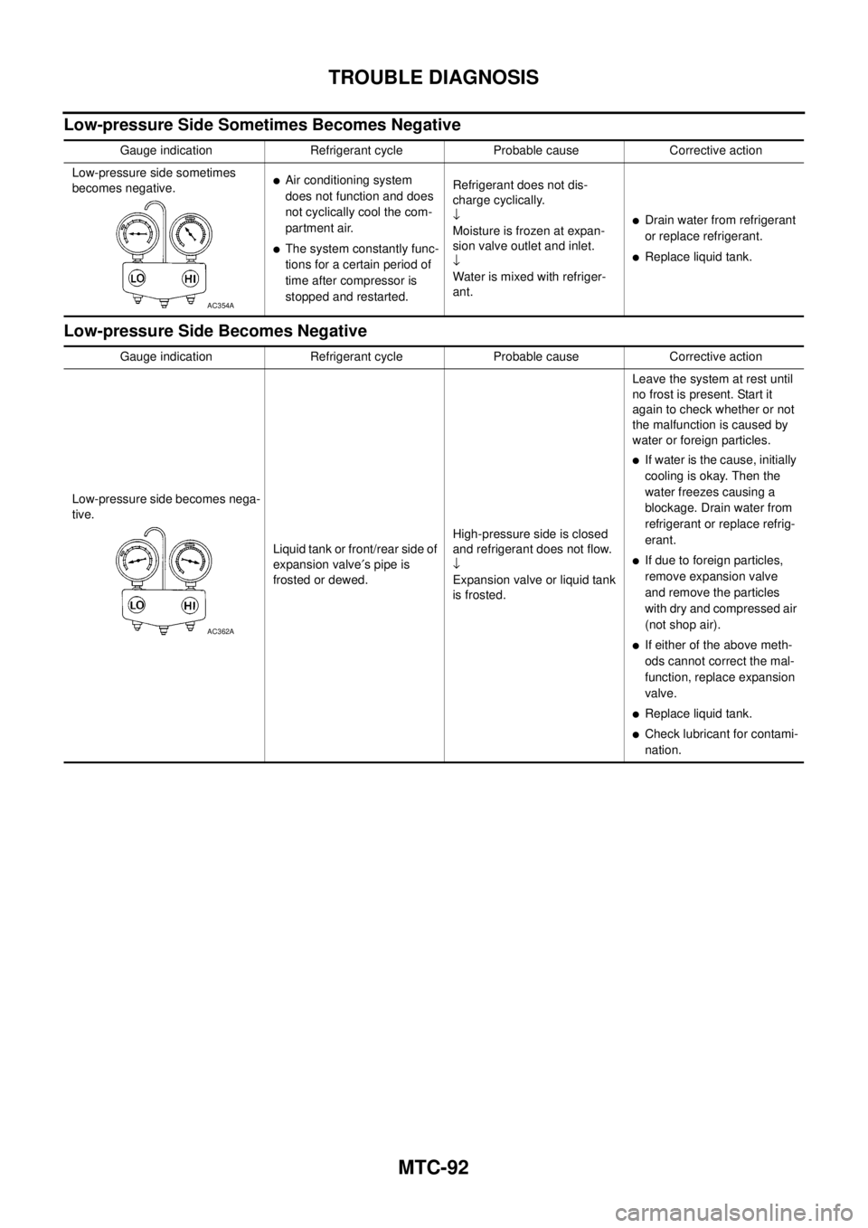
Low-pressure Side Sometimes Becomes Negative
Low-pressure Side Becomes Negative
Gauge indication Refrigerant cycle Probable cause Corrective action
Low-pressure side sometimes
becomes negative.
lAir conditioning system
does not function and does
not cyclically cool the com-
partment air.
lThe system constantly func-
tions for a certain period of
time after compressor is
stopped and restarted.Refrigerant does not dis-
charge cyclically.
¯
Moisture is frozen at expan-
sion valve outlet and inlet.
¯
Water is mixed with refriger-
ant.
lDrain water from refrigerant
or replace refrigerant.
lReplace liquid tank.
AC354A
Gauge indication Refrigerant cycle Probable cause Corrective action
Low-pressure side becomes nega-
tive.
Liquid tank or front/rear side of
expansion valve¢spipeis
frosted or dewed.High-pressure side is closed
and refrigerant does not flow.
¯
Expansion valve or liquid tank
is frosted.Leave the system at rest until
no frost is present. Start it
again to check whether or not
the malfunction is caused by
waterorforeignparticles.
lIf water is the cause, initially
cooling is okay. Then the
water freezes causing a
blockage. Drain water from
refrigerant or replace refrig-
erant.
lIf due to foreign particles,
remove expansion valve
and remove the particles
with dry and compressed air
(not shop air).
lIf either of the above meth-
ods cannot correct the mal-
function, replace expansion
valve.
lReplace liquid tank.
lCheck lubricant for contami-
nation.
AC362A