2005 NISSAN NAVARA tire type
[x] Cancel search: tire typePage 493 of 3171

SYSTEM DESCRIPTION
AV-5
C
D
E
F
G
H
I
J
L
MA
B
AV
Personal Audio Setting
The radio is designed to store several settings (volume, bass, treble, preset stations) with every NATS ignition
key used. Up to a maximum of 4 NATS keys can be registered. During the communication mentioned under
“Anti-Theft System”, the radio will recognize the used ignition key and select the accompanying settings.
VEHICLE INFORMATION SYSTEM
lThe status of audio system, fuel consumption, rear view monitor and navigation system are displayed.
lNAVI control unit receives the data signal from ECM, combination meter via CAN communication. It calcu-
lates the values of fuel economy, and trip computer from the received information and displays them.
NAVIGATION SYSTEM
Refer to Owner's Manual or navigation system Owner's Manual for navigation system operating instructions.
Location Detection Principle
The navigation system periodically calculates the vehicle's current
position according to the following three signals:
lTravel distance of the vehicle as determined by the vehicle
speed sensor
lTurning angle of the vehicle as determined by the gyroscope
(angular velocity sensor)
lDirection of vehicle travel as determined by the GPS antenna
(GPS information)
The current position of the vehicle is then identified by comparing the
calculated vehicle position with map data read from the map DVD-
ROM, which is stored in the DVD-ROM drive (map-matching), and
indicated on the screen as a vehicle mark. More accurate data is judged and used by comparing vehicle posi-
tion detection results found by the GPS with the result by map-matching.
The current vehicle position will be calculated by detecting the dis-
tance the vehicle moved from the previous calculation point and its
direction.
lTravel distance
Travel distance calculations are based on the vehicle speed
sensor input signal. Therefore, the calculation may become
incorrect as the tires wear down. To prevent this, an automatic
distance correction function has been adopted.
lTravel direction
Change in the travel direction of the vehicle is calculated by a
gyroscope (angular velocity sensor) and a GPS antenna (GPS
information). They have both advantages and disadvantages.
More accurate traveling direction is detected because priorities are set for the signals from these two
devices according to the situation.
No communication from IMMU to radio 1. If NATS is malfunctioning, check NATS
system.
2. After NATS is repaired, reset radio to
NEW state by authorized representative
of Clarion.After switching on the radio, the radio will
display “SECURE” after 1 minute. Further
use of radio is impossible until communica-
tion is established again, or after radio is
reset by authorized representative of Clar-
ion.
When initialized between ECM and IMMU. Radio needs to be reset to NEW status by
authorized representative of Clarion.After switching on the radio, it will display
“SECURE” after 1 minute. Item Service procedure Description
SKIB1058E
Type Advantage Disadvantage
Gyroscope
(angular velocity sensor)Can detect the vehicle's turning angle
quite accurately.Direction errors may accumulate when vehicle is
driven for long distances without stopping.
GPS antenna
(GPS information)Can detect the vehicle's travel direction
(North/South/East/West).Correct direction cannot be detected when vehi-
cle speed is low.
SEL684V
Page 1341 of 3171

PRECAUTIONS
EI-3
C
D
E
F
G
H
J
K
L
MA
B
EI
PRECAUTIONSPFP:00001
Service NoticeEIS00DY1
lWhen removing or installing various parts, place a cloth or padding on the vehicle body to prevent
scratches.
lHandle trim, molding, instruments, grille, etc. carefully during removing or installing. Be careful not to soil
or damage them.
lApply sealing compound where necessary when installing parts.
lWhen applying sealing compound, be careful that the sealing compound does not protrude from parts.
lWhen replacing any metal parts (for example body outer panel, members, etc.), be sure to take rust pre-
vention measures.
Precautions for Supplemental Restraint System (SRS) “AIR BAG” and “SEAT
BELT PRE-TENSIONER”
EIS00DZ5
The Supplemental Restraint System such as “AIR BAG” and “SEAT BELT PRE-TENSIONER”, used along
with a front seat belt, helps to reduce the risk or severity of injury to the driver and front passenger for certain
types of collision. Information necessary to service the system safely is included in the SRS and SB section of
this Service Manual.
WARNING:
lTo avoid rendering the SRS inoperative, which could increase the risk of personal injury or death
in the event of a collision which would result in air bag inflation, all maintenance must be per-
formed by an authorized NISSAN/INFINITI dealer.
lImproper maintenance, including incorrect removal and installation of the SRS, can lead to per-
sonal injury caused by unintentional activation of the system. For removal of Spiral Cable and Air
Bag Module, see the SRS section.
lDo not use electrical test equipment on any circuit related to the SRS unless instructed to in this
Service Manual. SRS wiring harnesses can be identified by yellow and/or orange harnesses or
harness connectors.
Precautions for SRS “AIR BAG” and “SEAT BELT PRE-TENSIONER” ServiceEIS00DZ2
lDo not use electrical test equipment to check SRS circuits unless instructed to in this Service Manual.
lBefore servicing the SRS, turn ignition switch OFF, disconnect both battery cables and wait at least 3 min-
utes.
For approximately 3 minutes after the cables are removed, it is still possible for the air bag and seat belt
pre-tensioner to deploy. Therefore, do not work on any SRS connectors or wires until at least 3 minutes
have passed.
lThe air bag diagnosis sensor unit must always be installed with the arrow marks “Ü” pointing toward the
front of the vehicle for proper operation. Also check the air bag diagnosis sensor unit for cracks, deformi-
ties or rust before installation and replace as required.
lThe spiral cable must be aligned with the neutral position since its rotations are limited. Do not attempt to
turn steering wheel or column after removal of steering gear.
lHandle air bag module carefully. Always place driver and front passenger air bag modules with the pad
side facing upward and seat mounted front side air bag module standing with the stud bolt side facing
down.
lConduct self-diagnosis to check entire SRS for proper function after replacing any components.
lAfter air bag inflates, the front instrument panel assembly should be replaced if damaged.
Page 1619 of 3171
SERVICE DATA AND SPECIFICATIONS (SDS)
FSU-19
C
D
F
G
H
I
J
K
L
MA
B
FSU
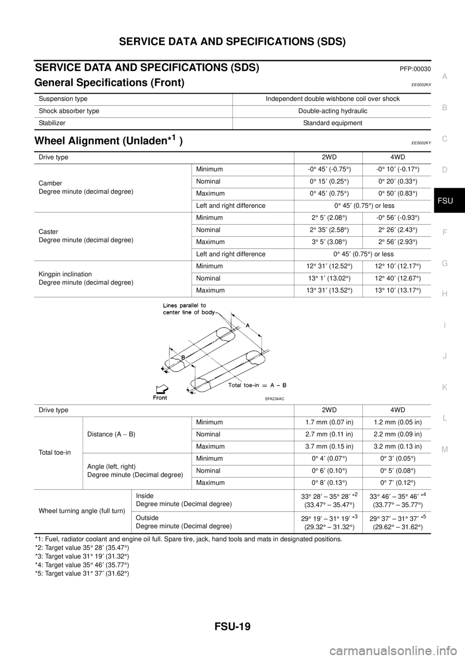
SERVICE DATA AND SPECIFICATIONS (SDS)PFP:00030
General Specifications (Front)EES002KX
Wheel Alignment (Unladen*1)EES002KY
*1: Fuel, radiator coolant and engine oil full. Spare tire, jack, hand tools and mats in designated positions.
*2: Target value 35°28¢(35.47°)
*3: Target value 31°19¢(31.32°)
*4: Target value 35°46¢(35.77°)
*5: Target value 31°37¢(31.62°) Suspension type Independent double wishbone coil over shock
Shock absorber type Double-acting hydraulic
StabilizerStandard equipment
Drive type2WD 4WD
Camber
Degree minute (decimal degree)Minimum -0°45¢(-0.75°)-0°10¢(-0.17°)
Nominal 0°15¢(0.25°)0°20¢(0.33°)
Maximum 0°45¢(0.75°)0°50¢(0.83°)
Left and right difference 0°45¢(0.75°)orless
Caster
Degree minute (decimal degree)Minimum 2°5¢(2.08°)-0°56¢(-0.93°)
Nominal 2°35¢(2.58°)2°26¢(2.43°)
Maximum 3°5¢(3.08°)2°56¢(2.93°)
Left and right difference 0°45¢(0.75°)orless
Kingpin inclination
Degree minute (decimal degree)Minimum 12°31¢(12.52°)12°10¢(12.17°)
Nominal 13°1¢(13.02°)12°40¢(12.67°)
Maximum 13°31¢(13.52°)13°10¢(13.17°)
Drive type2WD 4WD
Total toe-inDistance (A-B)Minimum 1.7 mm (0.07 in) 1.2 mm (0.05 in)
Nominal 2.7 mm (0.11 in) 2.2 mm (0.09 in)
Maximum 3.7 mm (0.15 in) 3.2 mm (0.13 in)
Angle (left, right)
Degree minute (Decimal degree)Minimum 0°4¢(0.07°)0°3¢(0.05°)
Nominal 0°6¢(0.10°)0°5¢(0.08°)
Maximum 0°8¢(0.13°)0°7¢(0.12°)
Wheel turning angle (full turn)Inside
Degree minute (Decimal degree)33°28¢–35°28¢*
2
(33.47°– 35.47°)33°46¢–35°46¢*
4
(33.77°– 35.77°)
Outside
Degree minute (Decimal degree)29°19¢–31°19¢*
3
(29.32°– 31.32°)29°37¢–31°37¢*
5
(29.62°– 31.62°)
SFA234AC
Page 1621 of 3171
SERVICE DATA AND SPECIFICATIONS (SDS)
FSU-21
C
D
F
G
H
I
J
K
L
MA
B
FSU
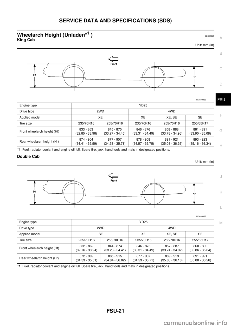
Wheelarch Height (Unladen*1)EES002L0
King Cab
Unit: mm (in)
*1: Fuel, radiator coolant and engine oil full. Spare tire, jack, hand tools and mats in designated positions.
Double Cab
Unit: mm (in)
*1: Fuel, radiator coolant and engine oil full. Spare tire, jack, hand tools and mats in designated positions.Engine type YD25
Drive type 2WD 4WD
Applied model XE XE XE, SE SE
Tire size 235/70R16 255/70R16 235/70R16 255/70R16 255/65R17
Front wheelarch height (Hf)833 - 863
(32.80 - 33.98)845 - 875
(33.27 - 34.45)846 - 876
(33.31 - 34.49)858 - 888
(33.78 - 34.96)861 - 891
(33.90 - 35.08)
Rear wheelarch height (Hr)874 - 904
(34.41 - 35.59)877 - 907
(34.53 - 35.71)878 - 908
(34.57 - 35.75)891 - 921
(35.08 - 36.26)893 - 923
(35.16 - 36.34)
LEIA0085E
Engine type YD25
Drive type 2WD 4WD
Applied model SE XE XE, SE SE
Tire size 235/70R16 255/70R16 235/70R16 255/70R16 255/65R17
Front wheelarch height (Hf)832 - 862
(32.76 - 33.94)844 - 874
(33.23 - 34.41)846 - 876
(33.31 - 34.49)857 - 887
(33.74 - 34.92)860 - 890
(33.86 - 35.04)
Rear wheelarch height (Hr)872 - 902
(34.33 - 35.51)885 - 915
(34.84 - 36.02)877 - 907
(34.53 - 35.71)889 - 919
(35.00 - 36.18)891 - 921
(35.08 - 36.26)
LEIA0085E
Page 1761 of 3171

IP-2
PRECAUTIONS
PRECAUTIONS
PFP:00001
Precautions for Supplemental Restraint System (SRS) “AIR BAG” and “SEAT
BELT PRE-TENSIONER”
EIS00DZ8
The Supplemental Restraint System such as “AIR BAG” and “SEAT BELT PRE-TENSIONER”, used along
with a front seat belt, helps to reduce the risk or severity of injury to the driver and front passenger for certain
types of collision. Information necessary to service the system safely is included in the SRS and SB section of
this Service Manual.
WARNING:
lTo avoid rendering the SRS inoperative, which could increase the risk of personal injury or death
in the event of a collision which would result in air bag inflation, all maintenance must be per-
formed by an authorized NISSAN/INFINITI dealer.
lImproper maintenance, including incorrect removal and installation of the SRS, can lead to per-
sonal injury caused by unintentional activation of the system. For removal of Spiral Cable and Air
Bag Module, see the SRS section.
lDo not use electrical test equipment on any circuit related to the SRS unless instructed to in this
Service Manual. SRS wiring harnesses can be identified by yellow and/or orange harnesses or
harness connectors.
Precautions for SRS “AIR BAG” and “SEAT BELT PRE-TENSIONER” ServiceEIS00DZ4
lDo not use electrical test equipment to check SRS circuits unless instructed to in this Service Manual.
lBefore servicing the SRS, turn ignition switch OFF, disconnect both battery cables and wait at least 3 min-
utes.
For approximately 3 minutes after the cables are removed, it is still possible for the air bag and seat belt
pre-tensioner to deploy. Therefore, do not work on any SRS connectors or wires until at least 3 minutes
have passed.
lThe air bag diagnosis sensor unit must always be installed with the arrow marks “Ü” pointing toward the
front of the vehicle for proper operation. Also check the air bag diagnosis sensor unit for cracks, deformi-
ties or rust before installation and replace as required.
lThe spiral cable must be aligned with the neutral position since its rotations are limited. Do not attempt to
turn steering wheel or column after removal of steering gear.
lHandle air bag module carefully. Always place driver and front passenger air bag modules with the pad
side facing upward and seat mounted front side air bag module standing with the stud bolt side facing
down.
lConduct self-diagnosis to check entire SRS for proper function after replacing any components.
lAfter air bag inflates, the front instrument panel assembly should be replaced if damaged.
Page 2111 of 3171
LT-28
HEADLAMP -CONVENTIONAL TYPE-
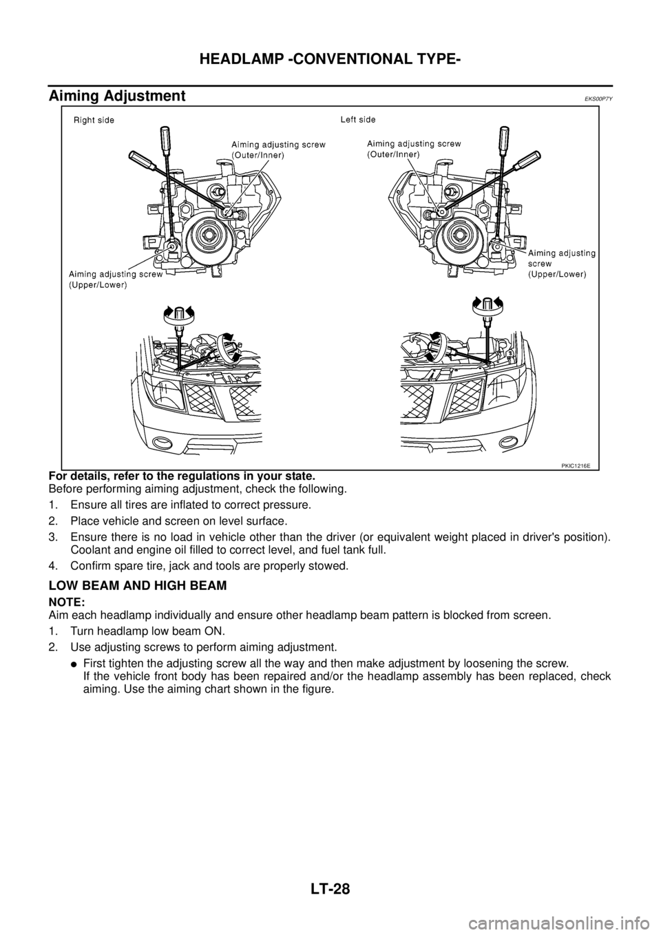
Aiming Adjustment
EKS00P7Y
For details, refer to the regulations in your state.
Before performing aiming adjustment, check the following.
1. Ensure all tires are inflated to correct pressure.
2. Place vehicle and screen on level surface.
3. Ensure there is no load in vehicle other than the driver (or equivalent weight placed in driver's position).
Coolant and engine oil filled to correct level, and fuel tank full.
4. Confirm spare tire, jack and tools are properly stowed.
LOW BEAM AND HIGH BEAM
NOTE:
Aim each headlamp individually and ensure other headlamp beam pattern is blocked from screen.
1. Turn headlamp low beam ON.
2. Use adjusting screws to perform aiming adjustment.
lFirst tighten the adjusting screw all the way and then make adjustment by loosening the screw.
If the vehicle front body has been repaired and/or the headlamp assembly has been replaced, check
aiming. Use the aiming chart shown in the figure.
PKIC1216E
Page 2168 of 3171
FRONT FOG LAMP
LT-85
C
D
E
F
G
H
I
J
L
MA
B
LT
Aiming AdjustmentEKS00P4D
The fog lamp is a semi-sealed beam type which uses a replaceable halogen bulb. Before performing aiming
adjustment, make sure of the following.
lKeep all tires inflated to correct pressure.
lPlace vehicle on level surface.
lSee that vehicle is unloaded (except for full levels of coolant, engine oil and fuel, and spare tire, jack, and
tools). Have the driver or equivalent weight placed in driver's seat.
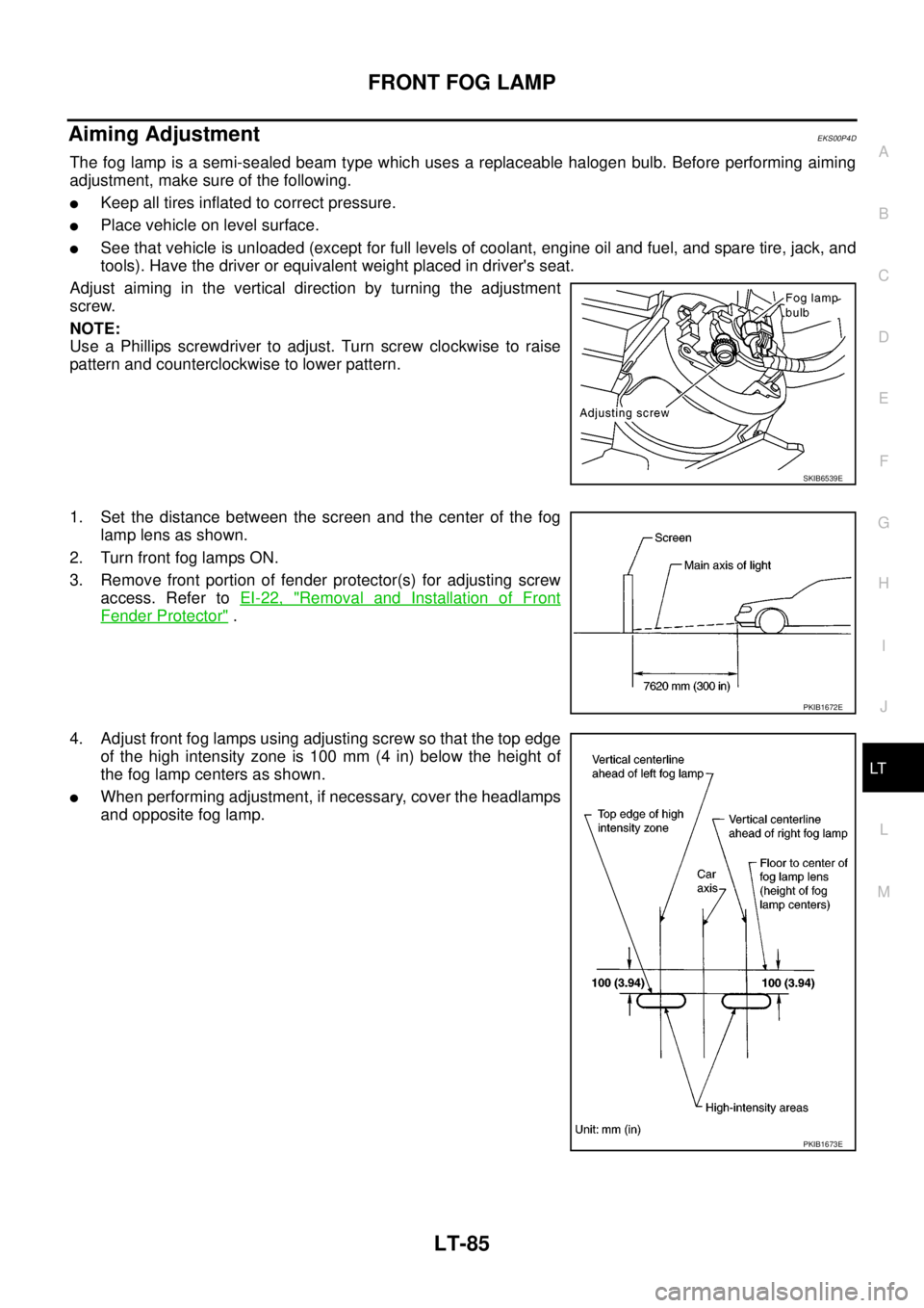
Adjust aiming in the vertical direction by turning the adjustment
screw.
NOTE:
Use a Phillips screwdriver to adjust. Turn screw clockwise to raise
pattern and counterclockwise to lower pattern.
1. Set the distance between the screen and the center of the fog
lamp lens as shown.
2. Turn front fog lamps ON.
3. Remove front portion of fender protector(s) for adjusting screw
access. Refer toEI-22, "
Removal and Installation of Front
Fender Protector".
4. Adjust front fog lamps using adjusting screw so that the top edge
of the high intensity zone is 100 mm (4 in) below the height of
the fog lamp centers as shown.
lWhen performing adjustment, if necessary, cover the headlamps
and opposite fog lamp.
SKIB6539E
PKIB1672E
PKIB1673E
Page 2816 of 3171
SERVICE DATA AND SPECIFICATIONS (SDS)
RSU-11
C
D
F
G
H
I
J
K
L
MA
B
RSU
SERVICE DATA AND SPECIFICATIONS (SDS)PFP:00030
General Specifications (Rear)EES002JK
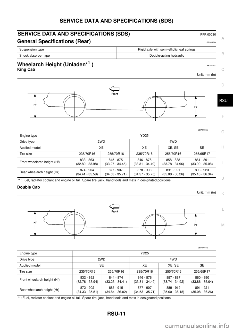
Wheelarch Height (Unladen*1)EES002JL
King Cab
Unit: mm (in)
*1: Fuel, radiator coolant and engine oil full. Spare tire, jack, hand tools and mats in designated positions.
Double Cab
Unit: mm (in)
*1: Fuel, radiator coolant and engine oil full. Spare tire, jack, hand tools and mats in designated positions.Suspension type Rigid axle with semi-elliptic leaf springs
Shock absorber type Double-acting hydraulic
Engine type YD25
Drive type 2WD 4WD
Applied model XE XE XE, SE SE
Tire size 235/70R16 255/70R16 235/70R16 255/70R16 255/65R17
Front wheelarch height (Hf)833 - 863
(32.80 - 33.98)845 - 875
(33.27 - 34.45)846 - 876
(33.31 - 34.49)858 - 888
(33.78 - 34.96)861 - 891
(33.90 - 35.08)
Rear wheelarch height (Hr)874 - 904
(34.41 - 35.59)877 - 907
(34.53 - 35.71)878 - 908
(34.57 - 35.75)891 - 921
(35.08 - 36.26)893 - 923
(35.16 - 36.34)
LEIA0085E
Engine type YD25
Drive type 2WD 4WD
Applied model SE XE XE, SE SE
Tire size 235/70R16 255/70R16 235/70R16 255/70R16 255/65R17
Front wheelarch height (Hf)832 - 862
(32.76 - 33.94)844 - 874
(33.23 - 34.41)846 - 876
(33.31 - 34.49)857 - 887
(33.74 - 34.92)860 - 890
(33.86 - 35.04)
Rear wheelarch height (Hr)872 - 902
(34.33 - 35.51)885 - 915
(34.84 - 36.02)877 - 907
(34.53 - 35.71)889 - 919
(35.00 - 36.18)891 - 921
(35.08 - 36.26)
LEIA0085E