2005 NISSAN NAVARA remove seats
[x] Cancel search: remove seatsPage 460 of 3171
ATC-126
HEATER & COOLING UNIT ASSEMBLY
Removal and Installation
EJS006C9
REMOVAL
1. Discharge the refrigerant from the A/C system. Refer toATC-138, "Discharging Refrigerant".
2. Drain the coolant from the engine cooling system. Refer toCO-8, "
DRAINING ENGINE COOLANT".
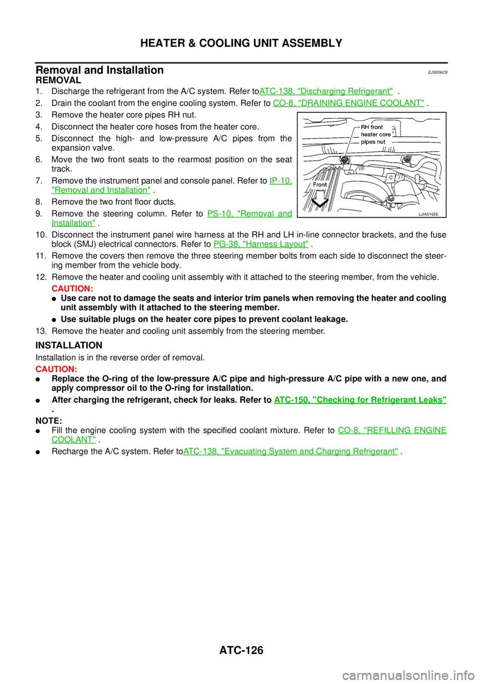
3. Remove the heater core pipes RH nut.
4. Disconnect the heater core hoses from the heater core.
5. Disconnect the high- and low-pressure A/C pipes from the
expansion valve.
6. Move the two front seats to the rearmost position on the seat
track.
7. Remove the instrument panel and console panel. Refer toIP-10,
"Removal and Installation".
8. Remove the two front floor ducts.
9. Remove the steering column. Refer toPS-10, "
Removal and
Installation".
10. Disconnect the instrument panel wire harness at the RH and LH in-line connector brackets, and the fuse
block (SMJ) electrical connectors. Refer toPG-38, "
Harness Layout".
11. Remove the covers then remove the three steering member bolts from each side to disconnect the steer-
ing member from the vehicle body.
12. Remove the heater and cooling unit assembly with it attached to the steering member, from the vehicle.
CAUTION:
lUse care not to damage the seats and interior trim panels when removing the heater and cooling
unit assembly with it attached to the steering member.
lUse suitable plugs on the heater core pipes to prevent coolant leakage.
13. Remove the heater and cooling unit assembly from the steering member.
INSTALLATION
Installation is in the reverse order of removal.
CAUTION:
lReplace the O-ring of the low-pressure A/C pipe and high-pressure A/C pipe with a new one, and
apply compressor oil to the O-ring for installation.
lAfter charging the refrigerant, check for leaks. Refer toATC-150, "Checking for Refrigerant Leaks"
.
NOTE:
lFill the engine cooling system with the specified coolant mixture. Refer toCO-8, "REFILLING ENGINE
COOLANT".
lRecharge the A/C system. Refer toATC-138, "Evacuating System and Charging Refrigerant".
LJIA0165E
Page 1374 of 3171
EI-36
BODY SIDE TRIM
REAR
CAUTION:
Wrap the tip of flat-bladed screwdriver with a cloth when removing metal clips from finishers.
Removal
1. Remove rear seats. Refer toSE-29, "Removal and Installation".
2. Remove storage boxes (if equipped). Refer toEI-38, "
FLOOR TRIM".
3. Remove rear kick plates RH/LH and seat belt anchor bolts.
4. Remove seatback latch strikers (Double cab models).
5. Remove jack storage cover, then remove jack.
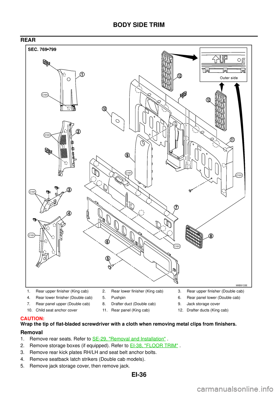
1. Rear upper finisher (King cab) 2. Rear lower finisher (King cab) 3. Rear upper finisher (Double cab)
4. Rear lower finisher (Double cab) 5. Pushpin 6. Rear panel lower (Double cab)
7. Rear panel upper (Double cab) 8. Drafter duct (Double cab) 9. Jack storage cover
10. Child seat anchor cover 11. Rear panel (King cab) 12. Drafter ducts (King cab)
MIIB9133E
Page 1377 of 3171
FLOOR TRIM
EI-39
C
D
E
F
G
H
J
K
L
MA
B
EI
Storage Box
REMOVAL
1. Remove front seats. Refer toSE-20, "FRONT SEAT".
2. Remove rear seats. Refer toSE-29, "
Removal and Installation".
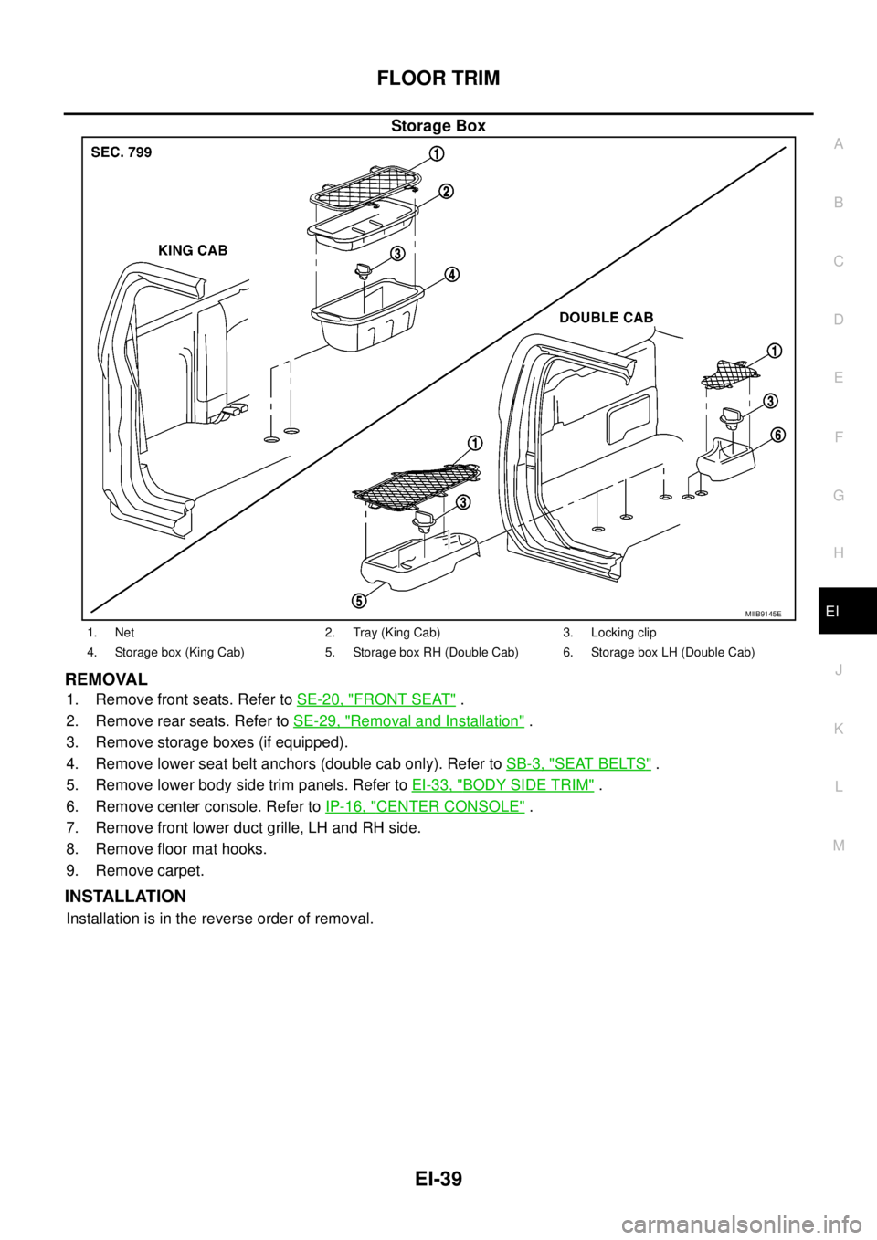
3. Remove storage boxes (if equipped).
4. Remove lower seat belt anchors (double cab only). Refer toSB-3, "
SEAT BELTS".
5. Remove lower body side trim panels. Refer toEI-33, "
BODY SIDE TRIM".
6. Remove center console. Refer toIP-16, "
CENTER CONSOLE".
7. Remove front lower duct grille, LH and RH side.
8. Remove floor mat hooks.
9. Remove carpet.
INSTALLATION
Installation is in the reverse order of removal.
MIIB9145E
1. Net 2. Tray (King Cab) 3. Locking clip
4. Storage box (King Cab) 5. Storage box RH (Double Cab) 6. Storage box LH (Double Cab)
Page 1475 of 3171
CYLINDER HEAD
EM-93
C
D
E
F
G
H
I
J
K
L
MA
EM
Compression pressure
Unit: kPa (bar, kg/cm2, psi)/rpm
lWhen engine rpm is out of the specified range, check the specific gravity of battery liquid. Measure
again under corrected conditions.
lIf engine rpm exceeds the limit, check valve clearance and combustion chamber components (valves,
valve seats, cylinder head gaskets, piston rings, pistons, cylinder bores, cylinder block upper and lower
surfaces) and measure again.
lIf compression pressure is low in some cylinders, apply engine oil from glow plug installation hole. Then
check pressure again.
–If compression pressure becomes normal after applying engine oil, piston ring may be worn or dam-
aged. Check piston ring for malfunction. If any, replace piston ring.
–If compression pressure is still low after applying engine oil, valve may be malfunctioning. Check valve
for malfunction. If contact malfunction is found, replace valve or valve seat.
lIf compression pressure in adjacent two cylinders is low after applying engine oil, pressure may be
leaking from gasket. In this case, replace cylinder head gasket.
9. Complete this operation as follows:
a. Turn the ignition switch to “OFF”.
b. Disconnect the battery cable from the negative terminal.
c. Install glow plug and install all the parts removed in step 4.
d. Install fuse [EGI (20A)].
e. Connect the battery cable to the negative terminal.
f. Using CONSULT-II make sure no DTC is indicated for items of self-diagnosis.
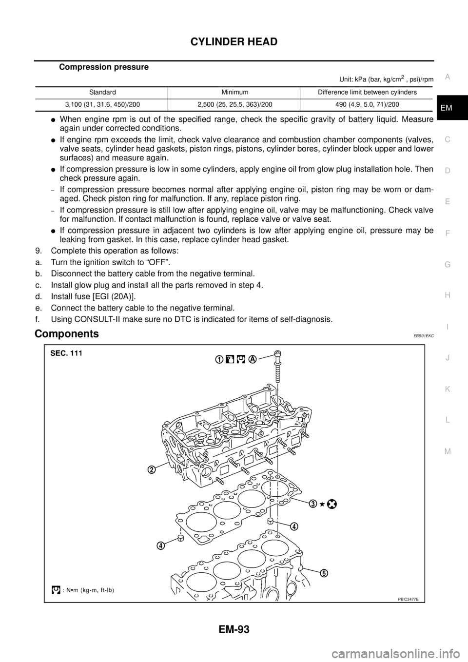
ComponentsEBS01EKC
Standard Minimum Difference limit between cylinders
3,100 (31, 31.6, 450)/200 2,500 (25, 25.5, 363)/200 490 (4.9, 5.0, 71)/200
PBIC3477E
Page 1482 of 3171
EM-100
CYLINDER HEAD
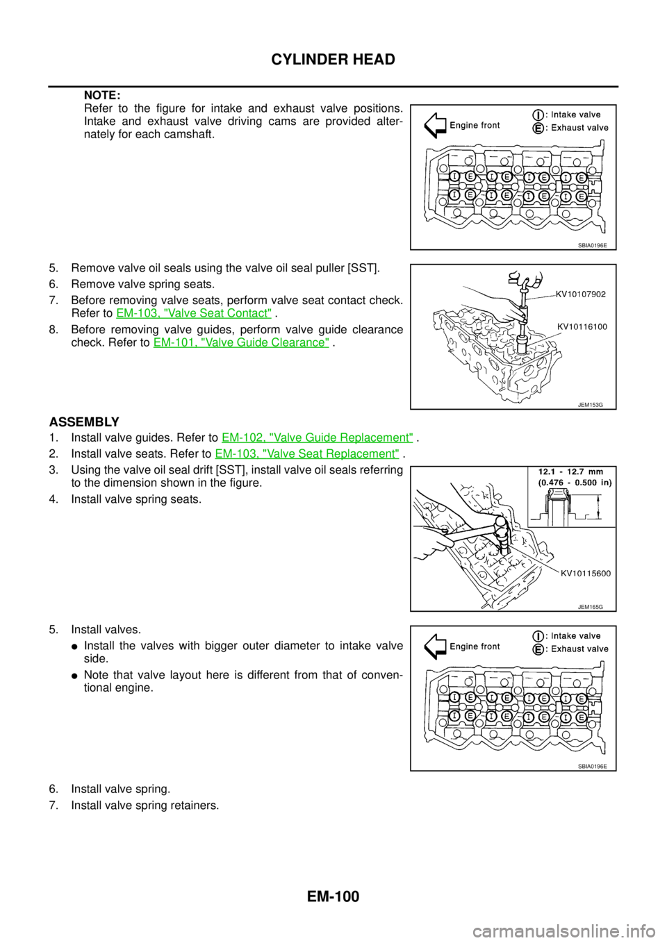
NOTE:
Refer to the figure for intake and exhaust valve positions.
Intake and exhaust valve driving cams are provided alter-
nately for each camshaft.
5. Remove valve oil seals using the valve oil seal puller [SST].
6. Remove valve spring seats.
7. Before removing valve seats, perform valve seat contact check.
Refer toEM-103, "
Va l v e S e a t C o n t a c t".
8. Before removing valve guides, perform valve guide clearance
check. Refer toEM-101, "
Valve Guide Clearance".
ASSEMBLY
1. Install valve guides. Refer toEM-102, "Valve Guide Replacement".
2. Install valve seats. Refer toEM-103, "
Valve Seat Replacement".
3. Using the valve oil seal drift [SST], install valve oil seals referring
to the dimension shown in the figure.
4. Install valve spring seats.
5. Install valves.
lInstall the valves with bigger outer diameter to intake valve
side.
lNote that valve layout here is different from that of conven-
tional engine.
6. Install valve spring.
7. Install valve spring retainers.
SBIA0196E
JEM153G
JEM165G
SBIA0196E
Page 2492 of 3171
HEATER & COOLING UNIT ASSEMBLY
MTC-105
C
D
E
F
G
H
I
K
L
MA
B
MTC
Removal and InstallationEJS005GY
REMOVAL
1. Discharge the refrigerant from the A/C system. Refer toMTC-118, "Discharging Refrigerant".
2. Drain the coolant from the engine cooling system. Refer toCO-8, "
DRAINING ENGINE COOLANT".
3. Remove the cowl top extension. Refer toEI-20, "
Removal and Installation".
4. Remove the exhaust system. Refer toEX-3, "
Removal and Installation".
5. Disconnect the heater hoses from the heater core.
6. Disconnect the high/low pressure pipes from the expansion valve.
7. Move the two front seats to the rearmost position on the seat track.
8. Remove the instrument panel and console panel. Refer toIP-10, "
Removal and Installation".
9. Remove the steering column. Refer toPS-11, "
Removal and Installation".
10. Disconnect the instrument panel wire harness at the RH and LH in-line connector brackets, and the fuse
block (J/B) electrical connectors. Refer toPG-38, "
Harness Layout".
11. Disconnect the steering member from each side of the vehicle body.
12. Remove the heater and cooling unit assembly with it attached to the steering member, from the vehicle.
CAUTION:
Use care not to damage the seats and interior trim panels when removing the heater and cooling
unit assembly with it attached to the steering member.
13. Remove the heater and cooling unit assembly from the steering member.
INSTALLATION
Installation is in the reverse order of removal.
CAUTION:
lReplace the O-ring of the low-pressure pipe and high-pressure pipe with a new one, and apply
compressor oil to it when installing it.
lAfter charging the refrigerant, check for leaks.
NOTE:
lFill the engine cooling system with the specified coolant mixture. Refer toCO-8, "REFILLING ENGINE
COOLANT".
lRecharge the A/C system. Refer toMTC-118, "Evacuating System and Charging Refrigerant".
Page 2699 of 3171
RF-22
SUNROOF
lAfter any adjustment, check sunroof operation and glass lid alignment.
lHandle glass lid with care so not to cause damage.
lFor easier installation, mark each point before removal.
CAUTION:
lAlways work with a helper.
lBefore removal, fully close the glass lid assembly. Then, after removal, do not move the motor
assembly.
lAfter installing the sunroof and glass lid, check gap adjustment to ensure there is no malfunction.
SUNROOF UNIT
Removal
CAUTION:
lAlways work with a helper.
lWhen taking sunroof unit out, use shop cloths to protect the seats and trim from damage.
lAfter installing the sunroof unit and glass lid, be sure to check gap adjustment to ensure there is
no malfunction.
1. Remove headlining. Refer toEI-40, "
Removal and Installation".
2. Remove the sunroof glass lid. Refer toRF-22, "
GLASS LID".
3. Disconnect the drain hoses.
4. Remove the mounting nuts from the front end and side rail.
5. Remove the mounting bolts to sunroof bracket and then remove the sunroof unit.
Installation
1. Position the sunroof frame assembly and temporally tighten the mounting bolts to the sunroof brackets.
2. Tighten the mounting nuts to the front end and side rail.
3. Tighten the mounting bolts to sunroof brackets.
4. Connect the drain hoses.
5. Install the sunroof glass lid. Refer toRF-22, "
GLASS LID".
6. Install headlining. Refer toEI-40, "
Removal and Installation".
GLASS LID
Removal
1. Open sunshade.
2. Ensure glass lid is closed.
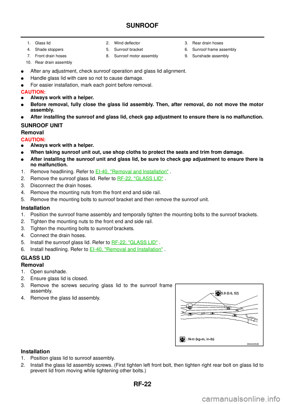
3. Remove the screws securing glass lid to the sunroof frame
assembly.
4. Remove the glass lid assembly.
Installation
1. Position glass lid to sunroof assembly.
2. Install the glass lid assembly screws. (First tighten left front bolt, then tighten right rear bolt on glass lid to
prevent lid from moving while tightening other bolts.)
1. Glass lid 2. Wind deflector 3. Rear drain hoses
4. Shade stoppers 5. Sunroof bracket 6. Sunroof frame assembly
7. Front drain hoses 8. Sunroof motor assembly 9. Sunshade assembly
10. Rear drain assembly
WIIA0252E
Page 2828 of 3171
SEAT BELTS
SB-11
C
D
E
F
G
I
J
K
L
MA
B
SB
Seat Belt InspectionEHS0026A
AFTER A COLLISION
WARNING:
Inspect all seat belt assemblies including retractors and attaching hardware after any collision.
NISSAN recommends that all seat belt assemblies in use during a collision be replaced unless the col-
lision was minor and the belts show no damage and continue to operate properly. Failure to do so
could result in serious personal injury in an accident. Seat belt assemblies not in use during a colli-
sion should also be replaced if either damage or improper operation is noted. Seat belt pre-tensioners
should be replaced even if the seat belts are not in use during a frontal collision in which the air bags
are deployed.
Replace any seat belt assembly (including anchor bolts) if:
lThe seat belt was in use at the time of a collision (except for minor collisions and the belts, retractors and
buckles show no damage and continue to operate properly).
lThe seat belt was damaged in an accident. (i.e. torn webbing, bent retractor or guide).
lThe seat belt attaching point was damaged in an accident. Inspect the seat belt attaching area for damage
or distortion and repair as necessary before installing a new seat belt assembly.
lAnchor bolts are deformed or worn out.
lThe seat belt pre-tensioner should be replaced even if the seat belts are not in use during the collision in
which the air bags are deployed.
PRELIMINARY CHECKS
1. Check the seat belt warning lamp for proper operation as follows:
a. Switch ignition ON. The seat belt warning lamp should illuminate.
b. Fasten driver's seat belt. The seat belt warning lamp should go out. If warning lamp remains illuminated,
Refer toDI-28, "
WARNING LAMPS".
2. If the air bag warning lamp is blinking, conduct self-diagnosis using CONSULT-II, and air bag warning
lamp. Refer toSRS-18, "
SRS Operation Check".
3. Check that the seat belt retractor, seat belt anchor and buckle bolts are securely attached.
4. Check the shoulder seat belt guide and shoulder belt height adjuster for front seats. Ensure guide swivels
freely and that belt lays flat and does not bind in guide. Ensure height adjuster operates properly and
holds securely.
5. Check retractor operation:
a. Fully extend the seat belt webbing and check for twists, tears or other damage.
b. Allow the seat belt to retract. Ensure that belt returns smoothly and completely into the retractor. If the
seat belt does not return smoothly, wipe the inside of the loops with a clean paper cloth, because dirt built
up in the loops of the upper anchors can cause the seat belts to retract slowly.
c. Fasten the seat belt. Check the seat belt returns smoothly and completely to the retractor. If the belt does
not return smoothly, the cause may be an accumulation of dust or dirt. Use the “SEAT BELT TAPE SET”
and perform the following steps.
Inspect the front seat belt through-anchor:
1. Pull the seat belt out to a length of 500 mm (19.69 in) or more.
2. Use a clip or other device to hold the seat belt at the center pillar belt opening.
3. Pass a thin wire through the through-anchor belt opening. Hold both ends of the wire and pull taut while
moving it up and down several times along the belt opening surface to remove dirt.
4. Any dirt that cannot be removed with the wire can be removed by cleaning the opening with a clean
cloth.
5. Apply tape at the point where the belt contacts the through-anchor belt opening.
NOTE:
Apply the tape so that there is no looseness or wrinkling.
6. Remove the clip holding the seat belt and check that the belt returns smoothly.
7. Repeat steps above as necessary to check the other seat belts.